Lerdge iX Parts list manual

www.lerdge.com
1
Lerdge-iX Usage Steps
Content
1. Select the power input voltage...................................................................................................2
2. Turn on the printer .....................................................................................................................2
3. Introduction of the key interface.................................................................................................3
4. Check the function of endstops..................................................................................................4
5. Check the function of motors .....................................................................................................4
6. Adjust the Z-axis origin position.................................................................................................5
7. Homing each axis ......................................................................................................................6
8. Check the travel space ..............................................................................................................6
9. Level the print platform ..............................................................................................................7
10. Check the leveling effect.........................................................................................................8
11. Preheating the hotend ............................................................................................................8
12. Load filament ..........................................................................................................................9
13. Print the first model...............................................................................................................10
14. Fine-tune the Z-axis for the first layer ...................................................................................10
15. Pause, stop and resume printing ..........................................................................................12
16. Automatically turn off the printer after finish..........................................................................13

www.lerdge.com
2
1. Select the power input voltage
The power supply used by Lerdge-iX can support 110V or 220V input voltage. Before turning on the
Lerdge-iX for the first time, you need to put power input voltage switch to the correct gear according
to the local mains grid voltage. The red switch on the side of the power supply is the power input
voltage switch.
Be sure to adjust the switch according to the local mains grid voltage! Never adjust the switch to
110V mode on a 220V grid, which will burn the power supply and other electronics! Do not adjust
the power supply to 220V mode under the 110V power grid, it may cause the power supply to work
abnormally, or some unexpected issues.
2. Turn on the printer
Firstly, connect the power cord of the Lerdge-iX printer to the socket, and press the red main switch
on the back of the printer. Secondly, press and hold the circular metal switch on the side of the
display, until the display boots interface and hear a "click" in the power management box, then
release the metal switch. At this time, the printer is turned on.
Turn the red
switch to the
bottom, the red
switch will
display 230V,
the power input
voltage is
switched to
210~230V
mode.
Turn the red
switch to the
top, the red
switch will
display 115V,
the power input
voltage is
switched to
100~115V
mode.

www.lerdge.com
3
3. Introduction of the key interface
Main interface:
Control Interface:
Printing Interface:
Control

www.lerdge.com
4
4. Check the function of endstops
Press the endstops of the X-axis and Y-axis respectively by hand, and observe whether the position
icons of the X and Y axes in the main interface have changed to the small house icon ;
Release the endstops of the X and Y axes, and the small house icon will return to the position icon,
which means that the function of endstops of the X and Y axes is normal.
For Z-axis optical endstop, find a small piece of opaque paper, insert it into the photoelectric slot of
the Z-axis optical endstop, observe whether the green indicator light on the optical endstop is on,
and then observe whether the Z-axis position icon in the main interface has become the small
house icon ; remove the small piece of paper from the photoelectric slot, the green indicator is
off, and the small house icon of the Z axis has changed to the position icon, which proves that the
function of Z-axis endstop is normal.
5. Check the function of motors
Move the print head and the hot bed to the middle of the X and Y axes by hand respectively; manually
rotate the lead screw to lift the X-axis cantilever, and ensure that the nozzle is at least 10mm away
from the print platform. Then enter the move control interface, click X+, X-, Y+, Y-, Z+, Z-, E+, E- in
turn.
Note that you need to click “+” and then “-” for any axis:

www.lerdge.com
5
✓ When X+ is clicked: the print head should move to the right
✓ When X- is clicked: the print head should move to the left
✓ When Y+ is clicked: the hot bed should move forward
✓ When Y- is clicked: the hot bed should move to the back
✓ When Z+ is clicked: The X-axis cantilever should move up
✓ When Z- is clicked: the X-axis cantilever should move down
✓ When E+ is clicked: the extruder gear should rotate counterclockwise
✓ When E- is clicked: the extruder gear should rotate clockwise
6. Adjust the Z-axis origin position
The trigger baffle on the Z-axis home adjuster can be extended or shortened to adjust the Z-axis
home position.
First, loosen the screw that fixes the trigger baffle on the Z-axis homing adjuster, extend the trigger
baffle to the longest, and then tighten the screw to fix the baffle. Then, manually rotate the lead
screw and lower the X-axis cantilever to ensure that the baffle can smoothly extend into the slot of
the Z-axis optical endstop, and trigger the Z-axis optical endstop, that is, the green indicator of the
Z-axis optical endstop is on (if it cannot be triggered, please refer to the “Lerdge-iX Q&A” document
on the Lerdge website). At this time, loosen the fixing screw of the trigger baffle, and try to extend
and retract the trigger baffle according to the distance between the nozzle and the printing platform,
until the distance between the nozzle and the platform is about 1~2mm when the Z-axis endstop is
just triggered.
Note: Please manually rotate the screw to control the movement of the X-axis cantilever in the Z-
axis direction to avoid problems such as crashes when adjusting for the first time. The Z-axis homing
shortcut icon can be used to realize the Z-axis movement during subsequent adjustments.
Z-axis home adjuster
The trigger baffle
Fixing screw

www.lerdge.com
6
7. Homing each axis
Click the position icons of X, Y, and Z axes on the main interface in turn, the system will perform the
homing motion of each axis in turn. That is: the slider of each axis will first move to the endstop,
then move in the opposite direction by 5mm after the endstop is triggered. Then moves towards the
endstop again at a slower speed, eventually stopping at the point where the endstop was triggered.
Afterwards, the "---" under each axis position icon on the main interface will become the specific
origin coordinate value.
8. Check the travel space
Enter the movement control interface according the above path, set the unit movement distance to
a number greater than 180, such as 200. Then click X+, Y+, X-, Y-, Z+, Z- in turn, observe the
positional relationship between the print head and the printing platform each time you operate, check
whether there is insufficient movement distance or wrong movement when moving each axis.

www.lerdge.com
7
9. Level the print platform
Enter the leveling control interface, click the manual leveling icon " ", (please be careful not to
click wrong! The left of the icon is automatic leveling icon. Currently Lerdge-iX is not equipped with
an automatic leveling probe. If you click the automatic leveling icon, the print head will hit the
platform!)
After clicking the manual leveling icon" ", Lerdge-iX will first perform the homing of each axis, and
then the print head will move to the position of the first point. At this time, by clicking the “ ” “ ”
icon, the distance between the nozzle and the platform can be adjusted. You can modify the unit
distance that the print head moves through the three values displayed at the bottom of the screen.
Adjust until the nozzle just touches the printing platform. It is recommended to judge the adjustment
effect by observing the gap between the nozzle and the platform. It is strongly not recommended to
use the method to feel the A4 paper being clamped.
When you finish the adjustment of one point, click the “ ” icon to continue to adjust the next point
until all the adjustment points are completed. Note: After the all leveling point is completed, be sure
to click the “ ” icon to end, so that the automatic leveling data can be saved!

www.lerdge.com
8
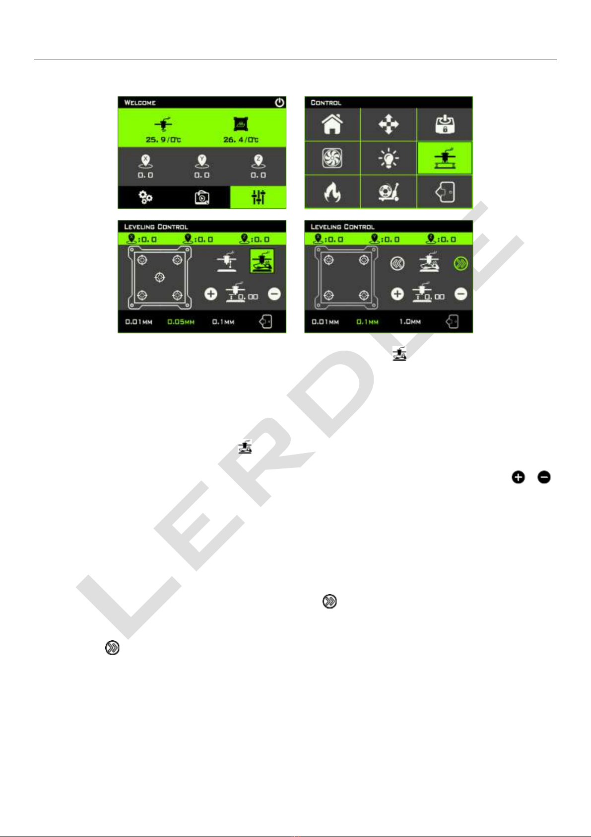
10.Check the leveling effect
In the leveling control interface, click the 5 “ ” icons in the hotbed frame on the left side of the
display, and the print head will move to the 5 positions corresponding to the actual hotbed in turn.
At this time, you can check the leveling effect of each position. The ideal effect should be that the
nozzle of the print head just touches the printing platform in five positions. In practice, it is normal if
there is a slight difference in a certain position. After all, it is a human judgment in the previous
leveling process.
In this case, you can adjust the Z-axis fine-tuning whose icon displays at the middle and lower
position on the right side of the display. Note: The adjustment at this time is overall adjustment of
the Z-axis, not a single point adjustment. The leveling needs to be re-executed if the difference
between the five points is large.
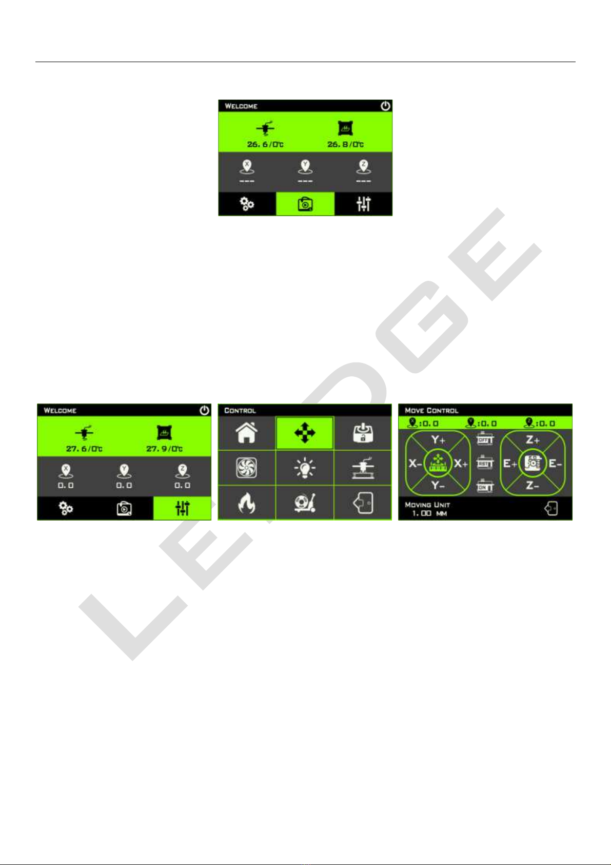
11.Preheating the hotend
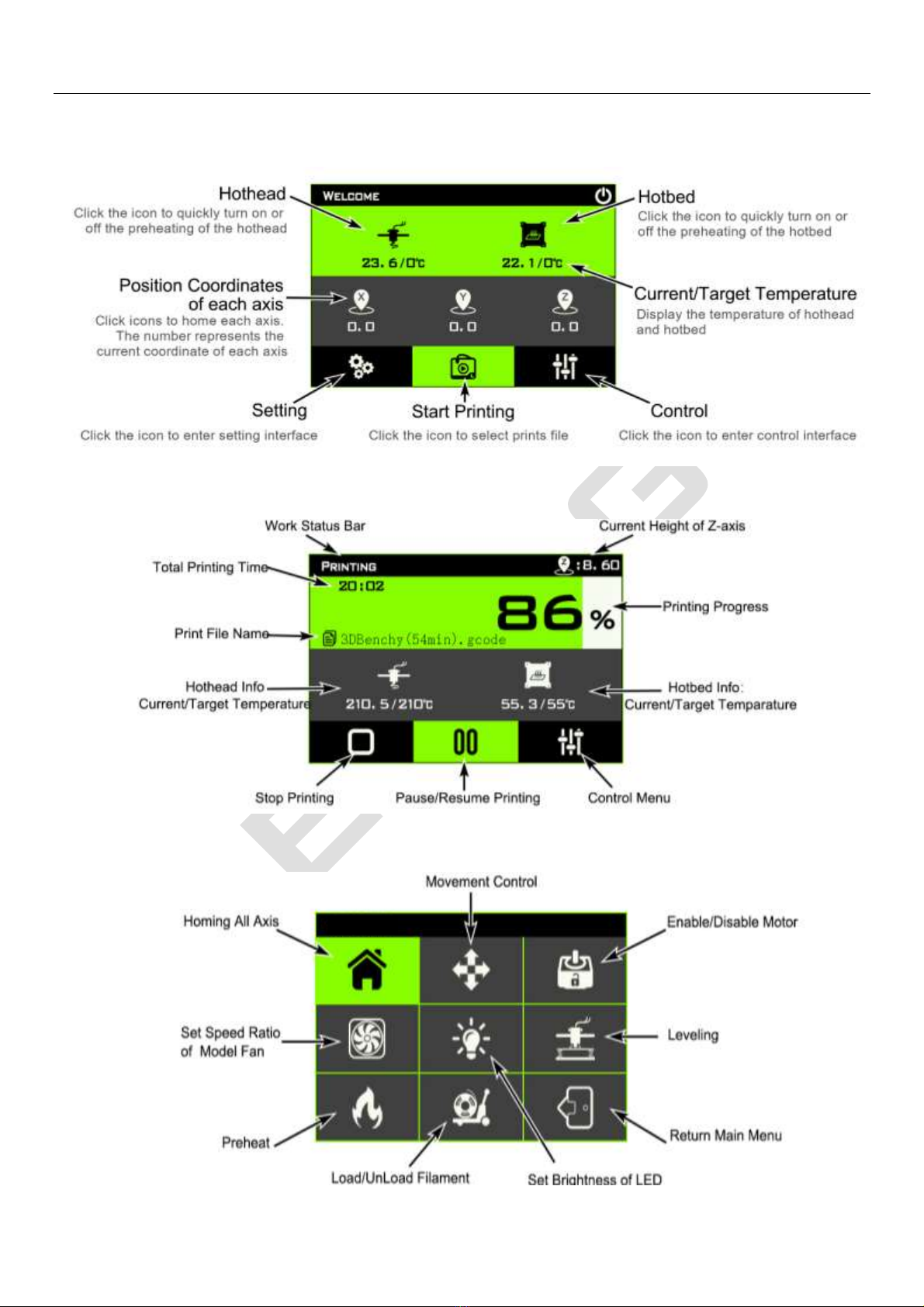
Firstly, check the temperature measurement function of the hotend. In the main interface, the format
of the temperature value below the icons of the hotend is displayed as xxx/xxx°C, and the value in
front of “/” represents the current real-time temperature of the hotend.
Please check whether the real-time temperature of the hotend be close to the room temperature.
The value behind the “/” is the heating target temperature of the hotend. When it is displayed as 0,
it means that the hotend stop heating.
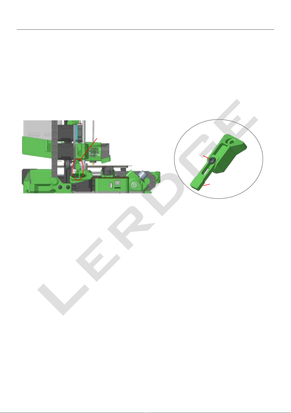
Secondly, lift the X-axis cantilever, at least ensure that the nozzle is at a distance of more than 5mm
from the printing platform, so that it is easy to observe the extrusion of the filament from the nozzle
or clean the nozzle. Then go back to the main interface, click the icon of the hothead and the hotbed,
and the target temperature under the icon of the hothead and the hotbed will be set. Then observe
whether the real-time temperature of the hotend starts to rise.

www.lerdge.com
9
12.Load filament
Cut the filament with scissors to a beveled angle, and insert the it into the extruder, and observe
whether the green filament runout indicator on the side of the extruder is on, make sure the filament
is inserted into the position of the extrusion wheel. Then enter the control interface, click the “ ”
icon, select the "Auto" option in the pop-up change filament interface, and click the " " icon, the
system can automatically load the filament into the print head, and pre-extrude a little when the
temperature is suitable.
Note: If the filament is not loaded or unloaded in place after the "Auto" option is executed once, do
not execute it again! Otherwise the filament or other accessories may be damaged! At this time, you
can switch to "1mm", "10mm" or "100mm" option by clicking the "Auto" icon, then click “ ” to load
the filament until the filament is extruded from the nozzle.

www.lerdge.com
10
13.Print the first model
Download the "3DBenchy(54min).gcode" testing gcode file on Lerdge website, copy it to the root
directory of the TF card or U disk, insert the TF card or U disk into the printer, and select
"3DBenchy(54min).gcode" as shown below file and start printing. Note that when selecting a print
file, please use the “ ” and “ ” icons to move the selection, and clicking the file name directly
has no effect.
14.Fine-tune the Z-axis for the first layer
Although the platform leveling operation is performed before printing starts, after all, the detection
during leveling is observed with the eyes, and not every user can accurately judge the distance
between the nozzle and the platform through observation. At this time, according to the adhesion
state of the filament extruded by the nozzle on the printing platform, the overall compensation of the
Z axis can be fine-tuned in real time to improve the first layer quality.
Refer to the following pictures to judge whether the distance between the print nozzle and the hot
bed is appropriate when the printer prints the first layer

www.lerdge.com
11
In the microtuning interface, “ ” means to increase the distance between the nozzle and the
platform, “ ” means to reduce the distance between the nozzle and the platform, and the value in
the middle represents the fine-tuning amount for a single operation of “ ” and “ ”, you can
choose 0.01mm, 0.05mm, 0.1mm three options. The value next to the print head icon is the current
offset value. After this value is changed, it is automatically saved when you close the microtuning
window, and you do not need to adjust it again the next time you print.
Please observe the real-time traces left by the filament extruded by the nozzle on the printing
platform. Adjust according to the actual situation after each fine-tuning operation. Do not rush to
operate frequently to avoid excessive adjustment and damage for the nozzle and the platform,
especially when reducing the distance between the nozzle and the platform.
Left square: the
distance between the
nozzle and the
platform on the first
layer is too large.
Middle square: the
distance between the
nozzle and the
platform on the first
layer is appropriate.
Right square: the
distance between the
nozzle and the
platform on the first
layer is too small.

www.lerdge.com
12
15.Pause, stop and resume printing
If you need to replace filament during printing or perform some other operations that require printing
to be temporarily suspended, you can click the " " icon at any time, the system will raise the print
head first, and then move the print head to the front left of the platform, and pause printing. Click
the " " icon during pause, the printer will move the print head to the position before the pause and
then resume printing.
Tips: In the process of resuming printing, the resuming point of printing may be more or less stuck
with some extra printing filament. Therefore, try to make the pause position occur inside the printed
model, in order to ensure the appearance of the model without any defects.
Click the " " icon during printing, and the system will reconfirm whether to stop printing and whether
to save the printing progress. The position of the Z axis cannot be moved if you choose saving the
printing progress, otherwise the height of the printing model will be incorrect when printing continues.
However, the X and Y axes can be moved arbitrarily. When you select the Gcode file that has saved
the printing progress again, the system will pop up a confirmation window. Select "Continue" to
continue printing the model that has not been printed before.
Besides, the Lerdge-iX is equipped with a power management module that can resume printing from
the unexpected power failure. The system can quickly save the current printing information and
printing progress if the Lerdge-iX encounters a power failure during printing. When the Lerdge-iX is
powered on again, select the unfinished Gcode file last time, and the system will prompt the same
window to confirm whether to continue printing. Select "continue" to resume printing from the
position where the last printing was stopped when encounters the power failure. Note that do not

www.lerdge.com
13
move the Z-axis during the process of resuming printing after the system is accidentally powered
off, otherwise it may cause layer misalignment in the Z-axis direction of the print model.
16. Automatically turn off the printer after finish
As shown in the figure below, select "shutdown after printing" in the control interface during the
printing process to automatically turn off the printer after the printing is completed; or add the "M87
S1" command at the beginning of the Gcode file. When the model is finished printing, the printer will
wait for the print nozzle to cool down below 40°C, and then power off the printer.
Other manuals for iX
1
Table of contents
Other Lerdge 3D Printer manuals