manuals.online logo
Brands
  1. Home
  2. •
  3. Brands
  4. •
  5. Leuze electronic
  6. •
  7. Lighting Equipment
  8. •
  9. Leuze electronic MLD510 Series User manual

Leuze electronic MLD510 Series User manual

MOUNTING INSTRUCTIONS
MONTAGEANWEISUNG
DE
MOUNTING INSTRUCTIONS
EN
SICHERHEITS-LICHTSCHRANKEN-SETS MLD-UDC
MLD-UDC LIGHT BEAM SAFETY DEVICE SETS
© Leuze electronic GmbH + Co. KG, In der Braike 1, 73277 Owen, Germany, We reserve the right to make changes 2012/06 Art. no. 700075
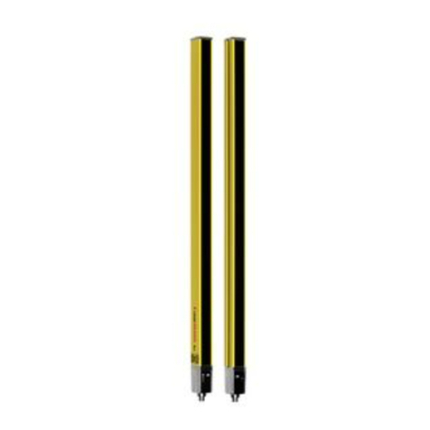
MLD520-RT3-UDC1300-S2 MLD-M003-UDC-1300-S2
MLD-UDC Komponenten (im Lieferumfang enthalten):
 UDC-yy00-S2
 Transceiver oder Sender MLD 500
 Empfänger MLD 500 oder Umlenkspiegel MLD-M00a
 MS-UDC/UMC-S2
 Fix-Anker W-FA/S
Klemmhalterung BT-P40
Bohrschablone
Anschlussleitungen für MLD 500 in passender Länge
(Maschinen-Interface) müssen separat bestellt werden!
HINWEIS:
Befolgen Sie sorgfältig alle Hinweise zum Sicherheits-Sensor in
der Original Betriebsanleitung auf der beiliegenden CD-ROM.
Montageschritte (Step):
1. Säulen am Boden befestigen
2. Säulen ausrichten
3. MLD 500 ausrichten und in Betrieb nehmen
4. Schutzscheibe einfügen (optional)
5. Checkliste – Vor der ersten Inbetriebnahme bearbeiten (siehe
Original Betriebsanleitung des Sicherheits-Sensors)
Erforderliche Werkzeuge:
 Inbusschlüssel-Satz
 Sechskantschlüssel-Satz
 Wasserwaage
 Bohrhammer mit 10 mm Betonbohrer
 Hammer
MLD-UDC components (included in delivery):
 UDC-yy00-S2
 MLD 500 transceiver or transmitter
 MLD 500 receiver or MLD-M00a Deflecting Mirror
 MS-UDC/UMC-S2
 Fastening anchor W-FA/S
BT-P40 clamp bracket
Drilling template
Connection cables in the correct lengths (machine
interface) for the MLD 500 must be ordered separately!
NOTE:
Carefully follow all notices regarding the safety sensor
in the original operating instructions on the enclosed CD-ROM.
Mounting steps:
1. Fasten the columns on the floor
2. Adjust columns
3. Align and start up MLD 500
4. Insert protective screen (optional)
5. Edit the Checklist - before the initial start-up (see original
operating instructions of the safety sensor)
Necessary tools:
 Allen key set
 Hexagon wrench set
 Spirit level
 Hammer drill with 10 mm concrete bit
 Hammer
MOUNTING INSTRUCTIONS
MONTAGEANWEISUNG
DE
MOUNTING INSTRUCTIONS
EN
SICHERHEITS-LICHTSCHRANKEN-SETS MLD-UDC
MLD-UDC LIGHT BEAM SAFETY DEVICE SETS
© Leuze electronic GmbH + Co. KG, In der Braike 1, 73277 Owen, Germany, Phone: +49 (0) 7021/573-0, Fax: -199, www.leuze.com We reserve the right to make changes 2012/03 Art. no. 700075
Step 1
Arbeitsschritte:
1. Säulen am Boden befestigen
 Bestimmen Sie den Befestigungsmittelpunkt der Säule
anhand der Bodenplatte und markieren Sie diesen auf dem
Boden.
 Setzen Sie die Bohrschablone auf den Mittelpunkt auf,
richten Sie sie aus und markieren Sie die Bohrungen.
 Bohren Sie die Befestigungslöcher nach Anweisung und
setzen Sie die Bodenanker ein.
 Setzen Sie die Säulen auf und schrauben Sie diese fest.
Work steps:
1. Fasten the columns on the floor
 Use the base plate to determine the mounting mid-
point of the column and make a mark on the floor.
 Set the drilling template on the center point, align it
and mark the bore holes.
 Drill the fixing holes according to instructions and
insert the floor anchors.
 Set the columns up and screw them on firmly.
Step 2
2. Säulen ausrichten
 Justieren Sie die Säule mit Hilfe der Libelle (1) grob.
 Justieren Sie die Säule an den Justageschrauben (2) mit
Hilfe der Wasserwaage in eine senkrechte Position.
 Lösen Sie die Inbusschrauben (3) und justieren Sie die
Säule axial.
 Libelle
 Justageschrauben
 Inbusschrauben
 Bohrungen für Bodenanker, Ø 10 mm
 Kunststoff-Federelement mit selbsttätiger Rückstellung
2. Adjust columns
 Roughly align the column using the spirit level (1).
 Align the column to the alignment screws (2) in a
vertical position using the spirit level.
 Loosen the Allen screws (3) and align the column
axially.
 Spirit level
 Alignment screws
 Allen screws
 Bore holes for floor anchors, Ø 10 mm
 Plastic spring element with automatic resetting
MOUNTING INSTRUCTIONS
MONTAGEANWEISUNG
DE
MOUNTING INSTRUCTIONS
EN
SICHERHEITS-LICHTSCHRANKEN-SETS MLD-UDC
MLD-UDC LIGHT BEAM SAFETY DEVICE SETS
© Leuze electronic GmbH + Co. KG, In der Braike 1, 73277 Owen, Germany, Phone: +49 (0) 7021/573-0, Fax: -199, www.leuze.com We reserve the right to make changes 2012/06 Art. no. 700075
Step 3
3. MLD 500 ausrichten und in Betrieb nehmen
 Stellen Sie den elektrischen Anschluss her. Verbinden Sie
hierzu die Anschlussleitung (Maschinen-Interface) mit dem
Sicherheits-Sensor und schließen Sie diese wie in der
Original Betriebsanleitung beschrieben an die Steuerungs-
komponenten der Maschine an.
 Schalten Sie den Sicherheits-Sensor ein.
 Justieren Sie die Höhe des Sicherheits-Sensor (Sender
und Empfänger). Die Geräte können nach Lösen der
Inbusschrauben (1) leicht in der Nut verschoben werden.
 Justieren Sie die axiale Ausrichtung des Sicherheits-Sensor
(Sender und Empfänger). Die komplette Säule mit dem ein-
gebauten Gerät kann nach Lösen der Inbusschrauben (2)
leicht gedreht werden.
Option:
Das Ausrichten wird durch die Nutzung der internen
Laserausrichthilfe wesentlich vereinfacht. Aktivieren Sie die
Laserausrichthilfe wie in der Original Betriebsanleitung
beschrieben.
3. Align and start up MLD 500
 Establish the electrical connection. To do this, connect
the connection cable (machine interface) to the safety
sensor and connect it to the machine control compo-
nents as described in the original operating instruc-
tions.
 Switch on the safety sensor.
 Adjust the height of the safety sensor (transmitter and
receiver). After the Allen screws are loosened (1), the
devices can be slid easily into the slot.
 Adjust the axial alignment of the safety sensor (trans-
mitter and receiver). After the Allen screws (2) have
been loosened, the entire column with the built-in
device can be rotated slightly.
Option:
Using the internal Laser Alignment Aid considerably
simplifies alignment. Activate the Laser Alignment Aid
as described in the original operating instructions.
MOUNTING INSTRUCTIONS
MONTAGEANWEISUNG
DE
MOUNTING INSTRUCTIONS
EN
SICHERHEITS-LICHTSCHRANKEN-SETS MLD-UDC
MLD-UDC LIGHT BEAM SAFETY DEVICE SETS
© Leuze electronic GmbH + Co. KG, In der Braike 1, 73277 Owen, Germany, We reserve the right to make changes 2012/03 Art. no. 700075
Step 4
4. Schutzscheibe einfügen (optional)
 Lösen Sie die obere Abdeckung der Säule (werkzeugfrei).
 Schieben Sie die Schutzscheibe in die vordere Nut ein.
 Rasten Sie die Abdeckung wieder ein.
4. Insert protective screen (optional)
 Loosen the upper cover of the column
(no tools needed).
 Slide the protective screen into the front slot.
 Click the cover back into place.
Step 5
5. Checkliste – Vor der ersten Inbetriebnahme bearbeiten
 Nehmen Sie die Maschine oder Anlage nach den Anwei-
sungen der Original Betriebsanleitung des Sicherheits-
Sensors in Betrieb.
5. Edit Checklist – before the initial start-up
 Start up the machine or system according to the
original operating instructions of the safety sensor.
Service / Support
Hotline: +49 8141 5350 – 111
E-Mail: [email protected]

This manual suits for next models

21

Other Leuze electronic Lighting Equipment manuals

Leuze electronic MLC 500 Series User manual

Leuze electronic

Leuze electronic MLC 500 Series User manual

Leuze electronic Advanced Tower Light Series User manual

Leuze electronic

Leuze electronic Advanced Tower Light Series User manual

Leuze electronic MLC 530 User manual

Leuze electronic

Leuze electronic MLC 530 User manual

Leuze electronic MLC 310 User manual

Leuze electronic

Leuze electronic MLC 310 User manual

Leuze electronic MLC 520 EX Series User manual

Leuze electronic

Leuze electronic MLC 520 EX Series User manual

Leuze electronic MS 70 LED 1 User manual

Leuze electronic

Leuze electronic MS 70 LED 1 User manual

Popular Lighting Equipment manuals by other brands

Nitecore SCL10 user manual

Nitecore

Nitecore SCL10 user manual

Davey Hurricane Swim Jet Installation and operating instructions

Davey

Davey Hurricane Swim Jet Installation and operating instructions

Knightsbridge LEDBATW Series Installation & maintenance manual

Knightsbridge

Knightsbridge LEDBATW Series Installation & maintenance manual

Bresser FM-300 instruction manual

Bresser

Bresser FM-300 instruction manual

Generay RGB-6X3S user manual

Generay

Generay RGB-6X3S user manual

Laserworld Club Series manual

Laserworld

Laserworld Club Series manual

LIVARNO home 1115-S manual

LIVARNO home

LIVARNO home 1115-S manual

EcoxGear SOUNDEXTREME SEI-SEUGLW48 user guide

EcoxGear

EcoxGear SOUNDEXTREME SEI-SEUGLW48 user guide

Good Earth Lighting G9713-T5-WHES-I quick start guide

Good Earth Lighting

Good Earth Lighting G9713-T5-WHES-I quick start guide

Philips hue Lightstrip Plus user manual

Philips

Philips hue Lightstrip Plus user manual

Equinox Systems QUADZILLA user manual

Equinox Systems

Equinox Systems QUADZILLA user manual

AVE COBRA WASH 200 MK2 user manual

AVE

AVE COBRA WASH 200 MK2 user manual

ViSAGE VIS0495.4 user manual

ViSAGE

ViSAGE VIS0495.4 user manual

e-conolight E-CSC Series installation instructions

e-conolight

e-conolight E-CSC Series installation instructions

Ayra TDC 33 user manual

Ayra

Ayra TDC 33 user manual

RUTEC VARDAflex Paket 5 RGBW manual

RUTEC

RUTEC VARDAflex Paket 5 RGBW manual

Uplus Lighting IP-L360 user manual

Uplus Lighting

Uplus Lighting IP-L360 user manual

Visual Comfort Griffith Swing Arm Assembly instructions

Visual Comfort

Visual Comfort Griffith Swing Arm Assembly instructions

manuals.online logo
manuals.online logoBrands
  • About & Mission
  • Contact us
  • Privacy Policy
  • Terms and Conditions

Copyright 2025 Manuals.Online. All Rights Reserved.