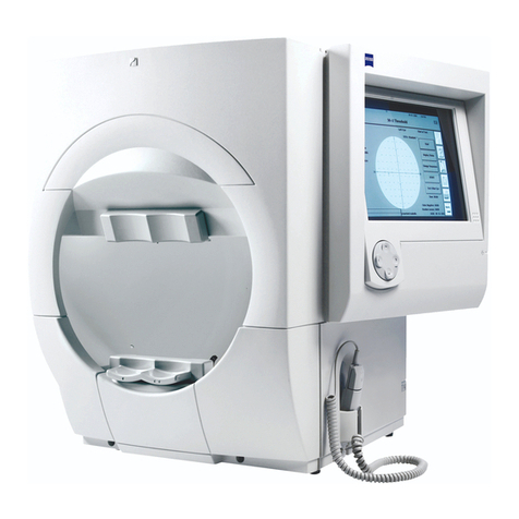
Zeiss humphrey HFA II-i series Quick start guide

Humphrey®
Field Analyzer
Series HFA II - i
Field Service Guide
CONFIDENTIAL & PROPRIETARY
Part No. 52235, Revision C
November 2005

PROPRIETARY NOTICE
Information contained in this document is copyright Carl Zeiss Meditec Incorporated and may not be
reproduced in full or in part by any person without prior written approval of Carl Zeiss Meditec. Its
purpose is to provide the User with adequately detailed information so as to repair, maintain, and order
spare parts for the instrument supplied. Every effort has been made to keep the information contained
in this document current and accurate as of the date of publication or revision. However, no guarantee
is given or implied that the document is error-free or that it is accurate with regard to any specification.
TRADEMARK CREDITS
Humphrey Field Analyzer is a registered trademark of Carl Zeiss Meditec Inc.
All trademarks, registered trademarks, and trade names that appear in this manual are the property of
their respective holders.
Revision C ©2005 by Carl Zeiss Meditec Inc. All rights reserved.
Carl Zeiss Meditec Inc.
5160 Hacienda Drive
Dublin, CA 94568
ii

REVISION CONTROL LIST
Document: Field Analyzer Series HFA II - i Field Service Guide
Part No.: 52235 - Revision C
Issued Date: November 2005
Listed at the bottom of each page is the part number of the field service guide, along with the Revision
letter and date for that page (for example, 52235C1105). Subsequent revisions to a page will be noted
by a corresponding change to the Revision letter and date.
Pages in this document are at Revision C unless noted otherwise below.
Note - The Revision “B” Humphrey Field Analyzer Series HFA II-i Field Service Guide, P/N 52235
has been revised to Revision “C”. The new revision updates all references from “Humphrey Systems”
to “Carl Zeiss Meditec Inc. (CZMI)”.
Page Revision Page Revision Page Revision Page Revision
iii


Humphrey Field Analyzer II - i Table of Contents
Confidential and Proprietary
52235C1105 v Field Service Guide
Table of Contents
Section 1 - General Information
1.1 AboutThisFieldServiceGuide ................................ 1-3
1.1.1 General Information ................................... 1-3
1.1.2 Conventions ......................................... 1-4
1.2 AboutServiceBulletins ...................................... 1-4
1.3 HFA II - i ServiceStrategy .................................... 1-5
1.3.1 Two-LevelServiceStrategy.............................. 1-5
1.3.2 Three Steps to Completing an HFA II - i ServiceCall .......... 1-5
1.3.3 HFA II - i FieldServicePaperworkRequirements ............. 1-6
1.4 ConfigurationParameters .................................... 1-8
1.5 Precautions ............................................... 1-8
1.6 InternalLayout ........................................... 1-10
1.7 SpecialTopics ............................................ 1-10
1.7.1 TheTouchScreen ................................... 1-10
1.7.2 GazeTracking....................................... 1-11
1.7.3 Head Tracking / Auto Pupil / Vertex Monitoring ............. 1-14
1.7.4 HFA II - i LightIntensityFundamentals.................... 1-15
1.7.5 Comparing HFA II and the HFA II - i ..................... 1-15
1.8 Peripherals .............................................. 1-20
1.9 Specifications............................................. 1-22
Section 2 PM and System Checkout
2.1 SystemCheckoutChecklist ................................... 2-3
2.2 PreventiveMaintenanceProcedure ............................. 2-8
Section 3 Parts Removal / Replacement
3.1 General Instructions ..........................................3-4
3.1.1 RemovalfromPowerTable .............................3-10
3.2 FrontCoverAssemblyRemoval................................3-11
3.3 RearCoverAssemblyRemoval ................................3-12
3.4 OperatorPanelAssemblyRemoval .............................3-13
3.5 DriveHousingAssemblyRemoval ..............................3-15

Table of Contents Humphrey Field Analyzer II - i
Confidential and Proprietary
Field Service Guide vi 52235C1105
3.6 CPU/BackplaneEnclosureRemoval ............................3-17
3.7 CPUandBackplaneRemoval .................................3-18
3.8 MotorDrivePCBRemoval ...................................3-19
3.9 SeparationoftheCPUPCBfromtheBackplaneBoard..............3-20
3.10 Power Supply Removal ......................................3-21
3.11 CRTPCBRemoval .........................................3-22
3.12 CRTRemoval .............................................3-23
3.13 Touch Screen Removal ......................................3-25
3.14 CCDCameraRemoval ......................................3-26
3.15 Fixation Interconnect PCB Removal ............................3-26
3.16 CentralFixationLED/BeamsplitterRemoval ......................3-27
3.17 ProjectionAssemblyRemoval .................................3-28
3.18 Projection Interconnect PCB Removal ...........................3-30
3.19 FilmWedge/MotorRemoval ..................................3-30
3.20 GlassWedge/MotorRemoval..................................3-31
3.21 Color Wheel / Aperture Wheel Removal .........................3-32
3.22 CarriageMotorRemoval .....................................3-33
3.23 ShutterRemoval ...........................................3-34
3.24 ShutterMotorRemoval ......................................3-35
3.25 CarriageMotorBeltRemoval..................................3-35
3.26 Horizontal(X-axis)TurretMotorRemoval ........................3-36
3.27 Horizontal(X-axis)TurretMotorBeltRemoval ....................3-37
3.28 Vertical(Y-axis)TurretBelt/MotorRemoval.......................3-39
3.29 BrightnessDetector(PCB)Replacement .........................3-40
3.30 LowerTurretRemoval.......................................3-41
3.31 TurretCableAssemblyRemoval ...............................3-42
3.32 Chinrest/Headrest Switch Assembly Removal .....................3-42
3.33 Chinrest Y-axis Belt/Motor Removal ............................3-43
3.34 Patient Support Horizontal (X-axis) Belt/Motor Removal .............3-44
3.35 Chinrest Vertical Slide and Lead Screw Removal ...................3-47
3.36 Chinrest Horizontal Slide Removal .............................3-48
3.37 TrialLensHolderAssemblyRemoval ...........................3-49
3.38 TopFanRemoval ..........................................3-50
3.39 BowlIRLEDAssemblyRemoval ...............................3-51

Humphrey Field Analyzer II - i Table of Contents
Confidential and Proprietary
52235C1105 vii Field Service Guide
3.40 Blue-YellowModule/BowlPlugRemoval ........................3-52
3.41 BowlRemoval .............................................3-52
3.42 ReflexGazeLEDRemoval....................................3-54
3.43 BowlLampAssemblyRemoval ................................3-54
3.44 IRBowlPlugRemoval/Installation ..............................3-55
3.45 Quarter-Turn Fastener Replacement ............................3-56
Section 4 Adjustment / Calibration
4.1 Introduction................................................4-3
4.2 RelatedProcedures ..........................................4-5
4.2.1 HFA II - i Calibration and Service Guidelines ................ 4-5
4.3 Calibration/DiagnosticsAccess................................ 4-6
4.4 ShowDialog .............................................. 4-6
4.5 SystemLog ............................................... 4-6
4.6 Database ................................................. 4-6
4.7 VideoTestPattern .......................................... 4-6
4.8 Calibration................................................ 4-7
4.8.1 Verification (obtaining Before and After light intensity calibration
values) ............................................. 4-7
4.8.1.1 Intensity/SpotRatio ........................... 4-7
4.8.1.2 Exerciser.................................... 4-11
4.8.1.3 QATests.................................... 4-12
4.8.2 Mechanical ......................................... 4-12
4.8.2.1 Projector.................................... 4-12
4.8.2.2 Shutter ..................................... 4-13
4.8.2.3 Aperture .................................... 4-14
4.8.2.4 Color ...................................... 4-15
4.8.2.5 Right/LeftHome ............................. 4-16
4.8.2.6 Offset ...................................... 4-16
4.8.2.7 Focus ...................................... 4-16
4.8.2.8 Detector .................................... 4-17
4.8.2.9 Target...................................... 4-18
4.8.3 Intensity ........................................... 4-20
4.8.3.1 Projector.................................... 4-20
4.8.3.1.1 White .................................. 4-20

Table of Contents Humphrey Field Analyzer II - i
Confidential and Proprietary
Field Service Guide viii 52235C1105
4.8.3.1.2 Blue ................................... 4-21
4.8.3.2 Bowl....................................... 4-23
4.8.3.2.1 White .................................. 4-23
4.8.3.2.2 Yellow ................................. 4-24
4.8.3.3 Wedge ..................................... 4-25
4.8.3.4 BlueCorrection .............................. 4-26
4.8.4 PrintCalValues ..................................... 4-30
4.8.5 Miscellaneous ....................................... 4-30
4.8.6 Camera ........................................... 4-30
4.8.6.1 CameraPosition/Size ......................... 4-30
4.8.6.2 GazePosition/Size ........................... 4-33
4.8.6.3 CameraIntensity ............................. 4-34
4.9 Adjustments.............................................. 4-36
4.9.1 Patient Support Horizontal Leadscrew Adjustment ........... 4-36
4.9.2 BeltTension ........................................ 4-37
4.9.3 EdgeDetector....................................... 4-37
4.9.4 TouchScreen ....................................... 4-37
4.9.5 CRTAdjustments .................................... 4-38
4.9.6 TrialLensHolder .................................... 4-42
4.9.7 CameraFocus ...................................... 4-45
4.9.8 IRLEDAlignments ................................... 4-46
Section 5 Troubleshooting
5.1 Introduction ................................................. 5-3
5.2 General Guidelines for Assembly Level Troubleshooting ............... 5-3
5.3 A Guide to HFA II - i ServiceDiagnosticAids ....................... 5-7
5.4 SoftwareModuleIdentifiers ..................................... 5-8
5.5 HFA II - i MotorExerciserandQATestPoints ....................... 5-9
5.6 PrintrexPrinterSelfTestsandErrorHandling ...................... 5-11
5.6.1 PrinterSelfTest ....................................... 5-11
5.6.2 PrintrexPrinterErrorsandErrorHandling ................... 5-11
5.7 Power-OnSelfTests ........................................ 5-13
5.7.1 MotorDriverBoardStartup .............................. 5-13
5.8 StartupStateErrors .......................................... 5-15
5.9 HexadecimalErrorCodes ..................................... 5-21
5.10 CommonErrorMessages/Solutions .............................. 5-23
Humphrey Field Analyzer II - i Table of Contents
Confidential and Proprietary
52235C1105 ix Field Service Guide
Section 6 Diagrams
Figure 6-1. System Interconnect Diagram
Figure 6-2. Projection Path
Figure 6-3. CPU PCB
Figure 6-4. Backplane Board
Figure 6-5. Motor Driver PCB Projection Assembly
Figure 6-6. Fixation Interconnect PCB
Figure 6-7. Patient Support Assembly
Figure 6-8. Power Entry and Power Supply
Figure 6-9. Projection Assembly
Figure 6-10. Memory Module Drives
Figure 6-11. Component Locations – CPU PCBs
Figure 6-12. Component Locations – Motor Driver PCBs
Section 7 Parts
7.1 Introduction ................................................ 7-3
7.2 PartsOrders—U.S.DomesticServiceOperations................... 7-3
7.3 PartsOrders—InternationalServiceOperations .................... 7-3
7.4 Returning Instruments / Defective Parts ........................... 7-4
7.4.1 Equipment Return Authorization ........................... 7-4
7.4.2 Packing the Instrument for Shipment ....................... 7-4
7.4.3 Returning Defective Parts ................................ 7-4
7.5 RecommendedSpares........................................ 7-5
7.6 LevelIPartsLists ............................................ 7-6
7.6.1 Accessories/Supplies/Consumables ......................... 7-6
7.6.2 Software ............................................. 7-8
7.6.3 Peripherals ........................................... 7-8
7.7 IllustratedPartsBreakdown .................................... 7-9
7.7.1 Shipping Materials and Repack Instructions ................. 7-10
7.7.2 Miscellaneous–1 ...................................... 7-14
7.7.3 Miscellaneous–2 ...................................... 7-16
7.7.4 Patient Support Assembly ............................... 7-20
7.7.5 Chinrest / Trial Lens Holder Assembly ..................... 7-22
7.7.6 ProjectionAssembly ................................... 7-24
7.7.7 ProjectorAssembly .................................... 7-26

Table of Contents Humphrey Field Analyzer II - i
Confidential and Proprietary
Field Service Guide x 52235C1105
7.7.8 ProjectionTurretAssembly .............................. 7-28
7.7.9 BowlAssembly ....................................... 7-30
7.7.9.1 BowlAssembly ................................ 7-32
7.7.10OperatorPanelAssembly ............................... 7-34
7.7.11B/YLampAssembly ................................... 7-36
7.7.12DriveMountingAssemblies.............................. 7-38
7.7.13CPUBackplaneEnclosure .............................. 7-40
7.7.14PowerTable/PrinterAssemblies ......................... 7-44
Appendices
Appendix A. Tools, Test Equipment and Service Supplies ................. A-1
A.1 List of Tools, Test Equipment and Service Supplies ........... A-1
A.2 TheSpecialTools-WhatTheyAre/WhatTheyDo........... A-3
A.2.1 SoligorLightMeterSetup ........................ A-3
A.2.2 SoligorMountAdaptor .......................... A-3
A.2.3 BowlShroud ................................. A-3
A.2.4 TrialLensAlignmentAdaptor ..................... A-3
A.2.5 FakeEye .................................... A-5
A.2.6 ToolStandAssembly ........................... A-5
A.2.7 MirrorTool ................................... A-5
A.2.8 CRTOverlay ................................. A-5
A.2.9 Spot Positioning Cross Fixture .................... A-5
A.2.10 BrightnessDetectorAlignmentTarget ............... A-6
A.2.11 ProjectionMount .............................. A-7
A.2.12 Operator Panel Extension/Support ................. A-8
A.2.13 HardDriveLEDAssembly ....................... A-9
A.2.14 ServiceKey................................... A-9
A.2.15 Diagnostic Support Tool ......................... A-9
A.2.16 LoopbackTool ............................... A-10
A.2.17 StaticProtectionKit ........................... A-10
A.2.18 Communications Terminals ..................... A-10
A.2.19 HowToSetUpTheP-FactorDiskette ............. A-11
Appendix B. The Interface Ports .................................... B-1
B.1 General Information ................................... B-1
B.2 RS-232 Interface Hardware and Pin Assignments ............ B-3

Humphrey Field Analyzer II - i Table of Contents
Confidential and Proprietary
52235C1105 xi Field Service Guide
Appendix C. Data Transfers ...................................... C-1
C.1 SerialTransferModes .................................. C-1
C.2 InstallingtheSerialIortheSerialIITransferDisk ............. C-2
C.3 HFA I to HFA II - i SerialDataTransfer .................... C-3
C.4 HFA II To HFA II - i SerialDataTransfer ................... C-5
C.5 HFA II - i To HFA II - i SerialDataTransfer ................. C-7
C.6 HFA II - i ToEnsemble© SerialDataTransfer ............... C-9
C.7 HFA II - i ToThirdPartyProgramsSerialDataTransfer ....... C-11
Appendix D. Approved Parallel Laser Jet Printers ...................... D-1
Appendix E. Instrument/BIOS Configuration ........................... E-1
E.1 InstrumentConfiguration ............................... E-1
E.2 BIOSConfiguration ................................... E-3
Appendix F. Operating System ..................................... F-1
Appendix G. PInitializing the Cal/Config Data
PSetting Serial Number
PSetting the Hardware Options
PSettingtheSoftwareOptions........................... G-1
G.1 InitializingtheCal/ConfigData ........................... G-3
G.2 SettingSerialNumber.................................. G-3
G.3 SettingtheModel/HardwareOptions ...................... G-4
G.4 SettingtheSoftwareOptions............................. G-6
Appendix H. Calibration Printouts ................................... H-1
H.1 Cal/WedgePrintout .................................. H-1
H.2 AutomatedLightIntensityPrintouts ....................... H-8
Appendix I. Service Forms ......................................... I-1
Appendix J. System Screens and Logs ................................ I-1
J.1 BootScreen ......................................... J-1
J.2 UnitConfigurationScreen .............................. J-1
J.3 SystemLog.......................................... J-4
Appendix K. Data Loss Recovery ................................... K-1
K.1 DataLossPreventionTips .............................. K-1
K.2 DatabaseStructure .................................... K-2
K.3 TheFive“Rs”ofDatabaseRecovery ...................... K-2
K.4 DatabaseUtilities ..................................... K-3
K.4.1 RebuildHardDiskDatabase...................... K-3
K.4.2 RebuildFloppyDatabase ........................ K-4

Table of Contents Humphrey Field Analyzer II - i
Confidential and Proprietary
Field Service Guide xii 52235C1105
K.4.3 DeleteHardDiskDatabase....................... K-4
K.4.4 DeleteTemporaryDatabase ...................... K-4
K.4.5 ReconstructDatabase ........................... K-4
K.4.6 SecondaryDatabaseUtilities ..................... K-4
K.5 FloppyDiskette-TroubleshootingDialogue ................. K-5
K.6 HardDiskDrive-TroubleshootingDialogue................. K-6
K.7 MagneticOpticalDisks ................................. K-7
Appendix L. Initializing the Hard Disk ................................ L-1
Appendix M. Loading Application Software ............................ M-1
Appendix N. Special Software Options ............................... N-1
Appendix O. Upgrades ........................................... O-1
Appendix P. Cable Diagrams .......................................P-1
Appendix Q. Cleaning Optics ...................................... Q-1
Appendix R. Optional Software Installation ............................ R-1

Confidential and Proprietary
52235C1105 1 - 1 Field Service Guide
Section 1 - General Information
1.1 AboutThisFieldServiceGuide ............................... 1-3
1.1.1 GeneralInformation ................................. 1-3
1.1.2 Conventions ....................................... 1-4
1.2 AboutServiceBulletins...................................... 1-4
1.3 HFA II - i ServiceStrategy ................................... 1-5
1.3.1 Two-LevelServiceStrategy ........................... 1-5
1.3.2 Three Steps to Completing an HFA II - i ServiceCall ........ 1-5
1.3.3 HFA II - i FieldServicePaperworkRequirements ........... 1-6
1.4 ConfigurationParameters.................................... 1-8
1.5 Precautions............................................... 1-8
1.6 InternalLayout ........................................... 1-10
1.7 SpecialTopics ........................................... 1-10
1.7.1 TheTouchScreen ................................. 1-10
1.7.2 GazeTracking .................................... 1-11
1.7.3 HeadTracking/AutoPupil/VertexMonitoring ........... 1-14
1.7.4 HFA II - i LightIntensityFundamentals ................. 1-15
1.7.5 Comparing HFA II and the HFA II - i ................... 1-15
1.8 Peripherals .............................................. 1-20
1.9 Specifications ............................................ 1-22

General Information Humphrey Field Analyzer II - i
Confidential and Proprietary
Field Service Guide 1 - 2 52235C1105
Notes:

Humphrey Field Analyzer II - i General Information
Confidential and Proprietary
52235C1105 1 - 3 Field Service Guide
1.1 About This Field Service Guide
1.1.1 General Information
This Service Guide is the field service reference for troubleshooting, repair, adjustment, and
calibration of the Models 720i, 740iand 750iHFA II - i Field Analyzers, manufactured by
Carl Zeiss Meditec Inc. The information presented in this Guide assumes that the reader is
already trained and experienced in operation and service of the Humphrey Field Analyzer
Series 700.
This field service guide is designed to support Level 1 Field Service, which employs modular
replacement of printed circuit boards and other assemblies that are most effectively repaired
at a central repair facility. This is the service strategy used in U.S. domestic Field Service,
and in Carl Zeiss Meditec Service training classes. See Section 1.3 for additional information
regarding Level 1 and Level 2 Repair Center service.
The procedures in this field service guide assume that the reader is familiar with operation of
the instrument. Complete operating instructions are contained in the HFA II - i
User's Guide. Information contained in the User's Guide is not repeated in this field service
guide. The User's Guide can be ordered separately by standard Carl Zeiss Meditec parts
order. Refer to Section 7 for the User's Guide parts information.
The general layout of the field service guide is shown below. For greater detail, please refer
to the Table of Contents.
Level 1 Field Service Guide Layout
Section 1 General Information
Section 2 Preventive Maintenance & System Checkout
Section 3 Parts Removal/Replacement
Section 4 Adjustment/Calibration
Section 5 Troubleshooting
Section 6 Diagrams
Section 7 Parts
Appendices

General Information Humphrey Field Analyzer II - i
Confidential and Proprietary
Field Service Guide 1 - 4 52235C1105
1.1.2 Conventions
The following conventions apply in this manual:
PThe terms left, right, front and back of the instrument are as viewed from the
patient position, unless noted otherwise.
PDimensions are given in inches unless noted otherwise.
1.2 About Service Bulletins
Field Service Bulletins are a vital element of service support. Bulletins are used to quickly
convey technical information on a variety of field service topics, including:
Pinstrument design changes
Ptechnical problems and
corrections
Psoftware updates
Pnew troubleshooting procedures
Pproblem alerts
Pservice manual revisions
Pupgrade announcements/
procedures
Psystem checkout – checklist
Pservice disclaimer forms
Psystem work sheets
Service bulletins are used to issue revised pages for service manual/service guide updates.
Your service bulletins should be filed where easily accessible for quick reference.
NOTICE
Field Service Bulletins are Confidential and Proprietary, for the sole use of
personnel employed by Carl Zeiss Meditec, Carl Zeiss Meditec affiliates, and
authorized Carl Zeiss Meditec distributors.
Carl Zeiss Meditec has a well-deserved reputation for high quality, reliable
instruments, unsurpassed in the industry.
As a Carl Zeiss Meditec employee, affiliate, or distributor you are required to
handle your service bulletins as appropriate for proprietary and confidential
information.

Humphrey Field Analyzer II - i General Information
Confidential and Proprietary
52235C1105 1 - 5 Field Service Guide
1.3 HFA II - i Service Strategy
1.3.1 Two-Level Service Strategy
A two-level service strategy is used for the HFA II - i: Level 1 for on-site service; and Level 2
for Repair Center service. Level 1 service employs modular replacement, wherein faulty
circuit boards and certain other assemblies are replaced rather than repaired on-site. These
faulty assemblies are shipped to a Carl Zeiss Meditec Repair Center for repairs. There are
also certain procedures that require special equipment available only at a Repair Center.
Designated Repair Centers (currently Dublin, CA and Jena, Germany) are the second level
of service for the HFA II - i. The Repair Centers perform major circuit board troubleshooting
and repair, plus any other service action that requires special equipment or procedures not
available in the field.
Several of the circuit boards in the HFA II - i are multilayer boards and use Surface Mount
Technology (SMT) components. These boards require special equipment and techniques for
troubleshooting and repair.
All service procedures (including instrument calibration) can be performed in the field, except
for those listed below. For Carl Zeiss Meditec U.S. Domestic operations, the following
procedures must be performed at the Carl Zeiss Meditec Repair Center.
PCircuit board troubleshooting and component replacement
PRepair of floppy, tape, and hard drives.
PAlignment of projection carriage rails and first projection mirror (top turret mirror)
PRepair of power supply assembly
PRepair of camera assembly
1.3.2 Three Steps to Completing an HFA II - i Service Call
The basic approach to an HFA II - i service call is outlined below. This typical process
includes collection of general instrument calibration data and light intensity data both Before
service and again After service. The process is described in detail in Section 4.8.1. For
guidelines, refer to HFA II - i Field Service Paperwork Requirements (Section 1.3.3).
1. Obtain the Before Light Intensity instrument data (4.8.1).
This step assumes that the HFA II - i is operable; that is, it will power up to the
Main Menu without error. This data gives the service representative a base from
which to evaluate the light intensity operation of the instrument, and a point of
comparison if recalibration is required.

General Information Humphrey Field Analyzer II - i
Confidential and Proprietary
Field Service Guide 1 - 6 52235C1105
If a repair is required to render the instrument operable, and as long as the repair
does not affect the original light intensity data, the repair can be performed and
then the Before data can be acquired.
The following repairs will affect light intensity data:
• Hard Drive replacement or initialization;
• cleaning or replacement of the ND wedges, color wheel*, or brightness
detector;
• replacement of the Motor Driver PCB.
*Note - Cleaning or replacing the color wheel will not affect the white/white
Before light intensity data; it only affects the blue light intensity data.
2. Perform the needed instrument service.
This step includes any parts replacement, adjustments, calibration, cleaning, etc.
to repair, update and/or upgrade the instrument.
3. Obtain the After light intensity instrument data (4.8.1) if the Before data was not within
specifications, or if something was done during service that affects light intensity (see list
in step 1).
When instrument service has been fully completed (but before reinstalling the
outer covers), a final evaluation of the instrument may be required (see Section
2.1, System Checkout). During this step, the Before and After light intensity data
are compared. If necessary, a Calibration Notice is given to the customer.
1.3.3 HFA II - i Field Service Paperwork Requirements
The following guide identifies the paperwork that must be completed and sent to Carl Zeiss
Meditec Customer Service following each service call or preventive maintenance visit on the
HFA II - i by U.S. Domestic service engineers. For all service engineers, this guide
identifies actions essential to properly perform various types of service calls on the HFA II - i.
For all service calls:
GFSR
GBefore Foveal ‡
If replacing/initializing Hard Drive; cleaning/replacing brightness detector, ND wedges, or
color wheel; or replacing Motor Driver PCB:
GIf obtainable, include all items from list above under "For all service calls," plus items
listed below under "Additional if light intensity recalibration is required". If possible,
obtain Before paperwork prior to the repair.

Humphrey Field Analyzer II - i General Information
Confidential and Proprietary
52235C1105 1 - 7 Field Service Guide
Additional if upgrade to Blue-Yellow:
GBefore and After Light Intensity Verification Printouts
GAfter Foveal ‡
GCalibration Notice*, if needed.
If performing PM:
GCovered by items listed above under "For all service calls."
GBefore Light Intensity Verification Printouts
Additional if light intensity recalibration is required:
GBefore and After Light Intensity Verification Printouts
GAfter Foveal ‡
GCalibration Notice*, if needed.
Notes -
* Formerly called "Doctor Card" or "Doctor Letter."
‡ For Model 720i, see Section 4 in the HFA II - i Field Service Guide.

General Information Humphrey Field Analyzer II - i
Confidential and Proprietary
Field Service Guide 1 - 8 52235C1105
1.4 Configuration Parameters
Configuration parameters can be entered and stored in the system by the user. This data is
stored on the hard disk. Calibration data also is stored on the hard disk. There is the
possibility that this data may become altered or erased during servicing of the instrument.
To minimize the possibility of altering the calibration values, configuration parameters or
doctor setups during service, the following practices should be observed.
• Whenever possible, when servicing a customer's instrument, backup the
calibration values on the calibration values disk. This option is available via the
Calibration Menu.
• Whenever possible, when servicing a customer's instrument, backup the customer-
selected configuration. This option is available via the Setup and Additional
Setup menus.
• When finished servicing the instrument, restore the customer's configuration
selections.
• Never intentionally alter the customer's existing doctor setups.
1.5 Precautions
The following precautions should be observed whenever the HFA II - i is being installed or
serviced. Point out to the customer any potential hazard and the appropriate corrective action.
WARNING: The CRT and associated circuitry can deliver a lethal
shock. Always employ standard high-voltage safety precautions
when working around the CRT circuitry. DO NOT use metal tools
when making CRT adjustments.
General Safety Precautions
1. The instrument is equipped with a grounding-pin power plug. The instrument must be
plugged into an outlet with a properly grounded receptacle.
2. Ensure that the fuses installed in the instrument and the power table are of the proper
rating.
3. Use of an extension cord is not recommended. Doing so may compromise the safety of
the operator and/or patient.
4. Do not overload the AC outlet being used to operate the instrument.
Table of contents
Other Zeiss Measuring Instrument manuals

Zeiss
Zeiss AT 030 Operator's manual

Zeiss
Zeiss TEMPAR console User manual

Zeiss
Zeiss Humphrey II-i series User manual

Zeiss
Zeiss AURA handheld NIR Operating instructions

Zeiss
Zeiss AURA User manual

Zeiss
Zeiss CONTURA User manual

Zeiss
Zeiss MMZ M User manual

Zeiss
Zeiss GOM Scan 1 User manual

Zeiss
Zeiss Gom T-SCAN hawk Instructions for use

Zeiss
Zeiss Corona process User manual

Zeiss
Zeiss MCS 600 User manual

Zeiss
Zeiss HUMPHREY 720i User manual

Zeiss
Zeiss AURA User manual

Zeiss
Zeiss Humphrey Field Analyzer 3 User manual

Zeiss
Zeiss Humphrey Field Analyzer 3 User manual

Zeiss
Zeiss CenterMax User manual

Zeiss
Zeiss CONTURA G2 User manual

Zeiss
Zeiss MEL 80 User manual

Zeiss
Zeiss VISUREF 150 User manual