manuals.online logo
Brands
  1. Home
  2. •
  3. Brands
  4. •
  5. LevelOne
  6. •
  7. Switch
  8. •
  9. LevelOne Infinity IES-1080 User manual

LevelOne Infinity IES-1080 User manual

8 FE + 2 GE TX Managed Switch
Quick Installation Guide
Default Setting
IP
Login
Password
Console
IES-1080
8 FE + 2 GE TX Managed Switch
-
40 to 75C, DIN
Quick Installation Guide
192.168.1.10
root
[blank]
115200, n, 8, 1
40 to 75C, DIN
-rail
Quick Installation Guide
v1.00 - 1206
IES-1080 Page 1
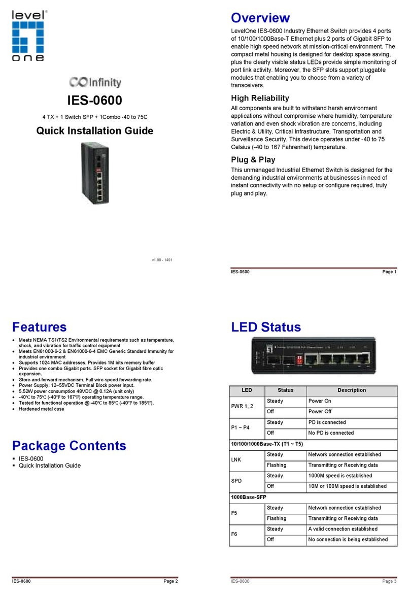
Overview
LevelOne IES-1080 Industry Ethernet Switch provides 8 ports
of 10/100Base-TX plus 2 ports of 10/100/1000Base Gigabit
Ethernet to enable high speed network at mission-critical
environment. This device is designed to be mounted on an
industry standard DIN-rail, plus the clearly visible status LEDs
provide simple monitoring of port link activity.
High Reliability
All components are built to withstand harsh environment
applications without compromise where humidity, temperature
variation and even shock vibration are concerns, including
Electric & Utility, Critical Infrastructure, Transportation and
Surveillance Security. This device operates under -40 to 75
Celsius (-40 to 167 Fahrenheit) temperature.
Resilient Ring Network
Supports Ring topology network providing simple installation
and ultra fast network recovery performance, less than 15ms.
Unlike much complex resilient topology, such as a redundant
star, the Ring simplifies the network design and requires less
cabling installation. In addition, fast network recovery time
helps minimize system downtime.
IES-1080 Page 2
Features
•Complies with EN50121-4 environmental requirements for
railway applications.
•Meets NEMA TS1/TS2 Environmental requirements such as
temperature, shock, and vibration for traffic control equipment.
•Meets EN61000-6-2 & EN61000-6-4 EMC Generic Standard
Immunity for industrial environment.
•Manageable via SNMP, Web-based, Telnet, and RS-232 console
port.
•Supports Command Line Interface in RS-232 console.
•Support 802.3/802.3u/802.3ab/802.3z/802.3x. Auto-negotiation:
10/100/1000Mbps, full/half-duplex; Auto MDI/MDIX.
•100Base-FX: Multi mode SC or ST type, Single mode SC or ST
type. 100Base-BX: WDM Single mode SC type.
•1000Base-SX/LX: Multi mode or Single mode SC type.
1000Base-BX: WDM Single mode SC type.
•Support 8192 MAC addresses. Provides 2M bits memory buffer.
•Alarms for power and port link failure by relay output.
•Power Supply: Redundant DC Terminal Block power inputs or
12VDC DC JACK with 100-240VAC external power supply.
•Operating voltage and max. current consumption: 0.92A @
12VDC, 0.46A @ 24VDC, 0.23A @ 48VDC. Power consumption:
11W Max.
•-40℃to 75℃(-40℉to 167℉) operating temperature range.
Tested for functional operation @ -40℃to 85℃(-40℉to 185℉).
•Supports Din-Rail or Panel Mounting installation
Package Contents
IES-1080
Quick Installation Guide
CD User Manual / Utility
IES-1080
Physical Description
Front Panel
Power Input
Terminal Block
PW1
PW2
Earth Ground
Relay
Relay Alarm w
arning signal disable for following:
1.
The relay contact closes if Power1 and Power2 are both failed but Power3
on
2.
The relay contact closes if Power3 is failed but Power1 and Power2 are both
on
•
The relay output is normal
Please do not connect any power source to this terminal to prevent shorting your
power supply.
•
There are three power inputs can be used. Redundant power function is supported
PW3
is DC Jack type with 12VD
Physical Description
Front Panel
Rear Panel
Power Input
+
12 – 48VDC
–
Power Ground
+
12 – 48VDC
–
Power Ground
Earth Ground
Relay
Output 1A @ 24VDC
arning signal disable for following:
The relay contact closes if Power1 and Power2 are both failed but Power3
The relay contact closes if Power3 is failed but Power1 and Power2 are both
The relay output is normal
open position when there is no power to the switch.
Please do not connect any power source to this terminal to prevent shorting your
There are three power inputs can be used. Redundant power function is supported
is DC Jack type with 12VD
C input
Page 3
Rear Panel
The relay contact closes if Power1 and Power2 are both failed but Power3
The relay contact closes if Power3 is failed but Power1 and Power2 are both
open position when there is no power to the switch.
Please do not connect any power source to this terminal to prevent shorting your
There are three power inputs can be used. Redundant power function is supported
IES-1080 Page 4
LED Status
LED
Status
Description
PW 1,2,3 Steady Power On
Off Power Off
10/100Base
-
TX & 100Base
-
FX
LNK/ACT Steady Network connection established
Flashing Transmitting or Receiving data
100 Steady Connection at 100Mbps
10/100/1000Base
-
TX
& 1000Base
-
FX & SFP
LNK/ACT Steady Network connection established
Flashing Transmitting or Receiving data
1000 Steady Connection at 1000Mbps
IES-1080
Console Configuration
1.
Connect to the switch console:
2.
Connect the DB9 straight cable to the RS
the device and the RS
computer running the terminal emulation application. Direct
access to the administration console is achieved by directly
connecting a terminal or a PC equipped with a terminal
emulation progr
am (such as HyperTerminal) to the switch
console port.
3.
Configuration settings of the terminal
4.
Baud rate: 115,200bps, Data bits: 8, Parity: none, Stop bit: 1,
Flow control: none.
5.
Press the “Enter” key. The Command Line Interface (CLI)
scr
een should appear as below:
6.
Logon to Exec Mode (View Mode):
7. At the “switch_
a login:” prompt just type in “root” and press
<Enter> to logon to Exec Mode (or View Mode). And the
“switch_a>” prompt will show on the screen.
8.
Logon to Privileged Exec Mode (En
9.
At the “switch_a>” prompt just type in “enable” and press
<Enter> to logon to Privileged Exec Mode (or Enable Mode).
And the “switch_a#” prompt will show on the screen.
10.
Logon to Configure Mode (Configure Terminal Mode):
11.
At the “switch_a
and press <Enter> to logon to Configure Mode (or Configure
Console Configuration
Connect to the switch console:
Connect the DB9 straight cable to the RS
-
232 serial
the device and the RS
-
232 serial port of the terminal or
computer running the terminal emulation application. Direct
access to the administration console is achieved by directly
connecting a terminal or a PC equipped with a terminal
am (such as HyperTerminal) to the switch
Configuration settings of the terminal
-
emulation program:
Baud rate: 115,200bps, Data bits: 8, Parity: none, Stop bit: 1,
Flow control: none.
Press the “Enter” key. The Command Line Interface (CLI)
een should appear as below:
Logon to Exec Mode (View Mode):
a login:” prompt just type in “root” and press
<Enter> to logon to Exec Mode (or View Mode). And the
“switch_a>” prompt will show on the screen.
Logon to Privileged Exec Mode (En
able Mode):
At the “switch_a>” prompt just type in “enable” and press
<Enter> to logon to Privileged Exec Mode (or Enable Mode).
And the “switch_a#” prompt will show on the screen.
Logon to Configure Mode (Configure Terminal Mode):
At the “switch_a
#” prompt just type in “configure terminal”
and press <Enter> to logon to Configure Mode (or Configure
Page 5
Console Configuration
232 serial
port of
232 serial port of the terminal or
computer running the terminal emulation application. Direct
access to the administration console is achieved by directly
connecting a terminal or a PC equipped with a terminal
-
am (such as HyperTerminal) to the switch
emulation program:
Baud rate: 115,200bps, Data bits: 8, Parity: none, Stop bit: 1,
Press the “Enter” key. The Command Line Interface (CLI)
a login:” prompt just type in “root” and press
<Enter> to logon to Exec Mode (or View Mode). And the
At the “switch_a>” prompt just type in “enable” and press
<Enter> to logon to Privileged Exec Mode (or Enable Mode).
And the “switch_a#” prompt will show on the screen.
Logon to Configure Mode (Configure Terminal Mode):
#” prompt just type in “configure terminal”
and press <Enter> to logon to Configure Mode (or Configure
IES-1080
Terminal Mode). And the “switch_a(config)#” prompt will
show on the screen.
12.
Set new IP address and subnet mask for Switch:
13.
At the “switch_a(config)#” pro
vlan1.1” and press <Enter> to logon to vlan 1 (vlan1.1 means
vlan 1). And the “switch_a(config
the screen.
14.
Command Syntax: “ip address A.B.C.D/M”. “A.B.C.D”
specifies IP address. “M” specifies IP subnet
255.0.0.0, 16:255.255.0.0, or 24: 255.255.255.0.
15.
For example, At the “switch_a(config
in “ip address 192.168.1.10/24” and press <Enter> to set
new IP address (192.168.1.10) and new IP subnet mask
(255.255.255.0) for Sw
Terminal Mode). And the “switch_a(config)#” prompt will
show on the screen.
Set new IP address and subnet mask for Switch:
At the “switch_a(config)#” pro
mpt just type in “interface
vlan1.1” and press <Enter> to logon to vlan 1 (vlan1.1 means
vlan 1). And the “switch_a(config
-
if)#” prompt will show on
Command Syntax: “ip address A.B.C.D/M”. “A.B.C.D”
specifies IP address. “M” specifies IP subnet
mask. “M”= 8:
255.0.0.0, 16:255.255.0.0, or 24: 255.255.255.0.
For example, At the “switch_a(config
-
if)#” prompt just type
in “ip address 192.168.1.10/24” and press <Enter> to set
new IP address (192.168.1.10) and new IP subnet mask
(255.255.255.0) for Sw
itch
Page 6
Terminal Mode). And the “switch_a(config)#” prompt will
Set new IP address and subnet mask for Switch:
mpt just type in “interface
vlan1.1” and press <Enter> to logon to vlan 1 (vlan1.1 means
if)#” prompt will show on
Command Syntax: “ip address A.B.C.D/M”. “A.B.C.D”
mask. “M”= 8:
255.0.0.0, 16:255.255.0.0, or 24: 255.255.255.0.
if)#” prompt just type
in “ip address 192.168.1.10/24” and press <Enter> to set
new IP address (192.168.1.10) and new IP subnet mask
IES-1080
Web Configuration
1. Login the switch:
2.
Specify the default IP address (192.168.1.10) of the switch in
the web browser. A login window will be shown as below:
3.
Enter the factory default login ID: root.
4.
Enter the factory default password (no password
5.
Then click on the “Login” button to log on to the switch.
Note: Please refer to User Manual for more detailed information
Web Configuration
Specify the default IP address (192.168.1.10) of the switch in
the web browser. A login window will be shown as below:
Enter the factory default login ID: root.
Enter the factory default password (no password
Then click on the “Login” button to log on to the switch.
Note: Please refer to User Manual for more detailed information
Page 7
Specify the default IP address (192.168.1.10) of the switch in
the web browser. A login window will be shown as below:
Enter the factory default password (no password
).
Then click on the “Login” button to log on to the switch.
Note: Please refer to User Manual for more detailed information

Other LevelOne Switch manuals

LevelOne FEP-0840 User manual

LevelOne

LevelOne FEP-0840 User manual

LevelOne ProCon GSW-2456 User manual

LevelOne

LevelOne ProCon GSW-2456 User manual

LevelOne GEP-2681 User manual

LevelOne

LevelOne GEP-2681 User manual

LevelOne FSW-0507TX User manual

LevelOne

LevelOne FSW-0507TX User manual

LevelOne GEP-0950 User manual

LevelOne

LevelOne GEP-0950 User manual

LevelOne ProCon GSW-1290 User manual

LevelOne

LevelOne ProCon GSW-1290 User manual

LevelOne 1650 User manual

LevelOne

LevelOne 1650 User manual

LevelOne IGP-0432 User manual

LevelOne

LevelOne IGP-0432 User manual

LevelOne FEP-0631 User manual

LevelOne

LevelOne FEP-0631 User manual

LevelOne GEP-0523 User manual

LevelOne

LevelOne GEP-0523 User manual

LevelOne GEU-1628 User manual

LevelOne

LevelOne GEU-1628 User manual

LevelOne GEP-2682 User manual

LevelOne

LevelOne GEP-2682 User manual

LevelOne FEP-1611 User manual

LevelOne

LevelOne FEP-1611 User manual

LevelOne GEP-2841 Programming manual

LevelOne

LevelOne GEP-2841 Programming manual

LevelOne GSW-2692 User manual

LevelOne

LevelOne GSW-2692 User manual

LevelOne OfficeCon GSW-2440 User manual

LevelOne

LevelOne OfficeCon GSW-2440 User manual

LevelOne GSW-2473 User manual

LevelOne

LevelOne GSW-2473 User manual

LevelOne IES-0843 User manual

LevelOne

LevelOne IES-0843 User manual

LevelOne GSW-0800TXM User manual

LevelOne

LevelOne GSW-0800TXM User manual

LevelOne FSW-1609TFX User manual

LevelOne

LevelOne FSW-1609TFX User manual

LevelOne FSW-1611TX User manual

LevelOne

LevelOne FSW-1611TX User manual

LevelOne GSW-0840T User manual

LevelOne

LevelOne GSW-0840T User manual

LevelOne IES-0600 User manual

LevelOne

LevelOne IES-0600 User manual

LevelOne IGP-0502 User manual

LevelOne

LevelOne IGP-0502 User manual

Popular Switch manuals by other brands

Guard master Centurion installation instructions

Guard master

Guard master Centurion installation instructions

Tripp Lite NetCommander B070-016-19 owner's manual

Tripp Lite

Tripp Lite NetCommander B070-016-19 owner's manual

Planet IGS-20160HPT Quick installation guide

Planet

Planet IGS-20160HPT Quick installation guide

FOR-A HVS-6000 Quick setup guide

FOR-A

FOR-A HVS-6000 Quick setup guide

q-Tech QSW-6300 Series Hardware  installation and reference guide

q-Tech

q-Tech QSW-6300 Series Hardware installation and reference guide

Rocket Fish RF-CRDRD Guide d'installation rapide

Rocket Fish

Rocket Fish RF-CRDRD Guide d'installation rapide

Guard master PROSAFE RPSE Series installation instructions

Guard master

Guard master PROSAFE RPSE Series installation instructions

HIK VISION DS-3T3512P user manual

HIK VISION

HIK VISION DS-3T3512P user manual

Planet XGSW-28040 user manual

Planet

Planet XGSW-28040 user manual

Planet POE-1200G user manual

Planet

Planet POE-1200G user manual

Black Box ACX4000 manual

Black Box

Black Box ACX4000 manual

AirLive L3-10XGF12 Quick setup guide

AirLive

AirLive L3-10XGF12 Quick setup guide

ICRealtime PWR-POE-8-V3 quick start guide

ICRealtime

ICRealtime PWR-POE-8-V3 quick start guide

Avtech RMA-RELAY-SEN Installation note

Avtech

Avtech RMA-RELAY-SEN Installation note

wattstopper WI-200 user manual

wattstopper

wattstopper WI-200 user manual

HYDACELECTRONIC EDS 820 operating manual

HYDACELECTRONIC

HYDACELECTRONIC EDS 820 operating manual

Tripp Lite B024-DUA8-SL owner's manual

Tripp Lite

Tripp Lite B024-DUA8-SL owner's manual

Black Box LGB616A user manual

Black Box

Black Box LGB616A user manual

manuals.online logo
manuals.online logoBrands
  • About & Mission
  • Contact us
  • Privacy Policy
  • Terms and Conditions

Copyright 2025 Manuals.Online. All Rights Reserved.