Leviat HALFEN PSA User manual

®
HALFEN PSA INST_PSA 11/20
Assembly Instructions•Montageanleitung
Attachment system for
personal fall protection
Anschlagsystem
für persönliche
Sicherheitsausrüstung
D
GB

A
t
t
a
c
h
m
e
n
t
f
o
r
F
a
l
l
P
r
o
t
e
c
t
i
o
n
m
a
x
.
2
P
e
r
s
.
2© 2020 · INST_PSA 11/20 · www.halfen.com
HALFEN PSA Assembly Instructions
Deutsch English
The supplied identification cap
identifies the fixing anchor as an
anchor point suitable for personal
protection equipment for a maximum
of two people.
Area of application
The HALFEN PSA is a fixing system
for attaching personal protection
equipment (PPE) to prevent fall
in accordance with DIN EN 795
and CEN/TS 16415.
Up to 2 people can be attached to
one single anchor point to safely
carry out construction, assembly
or maintenance work.
The HALFEN PSA Fixing system
(Anchor fixing point) consists of
the following components:
DEMU Fixing anchor T-FIXX
M16×110 (A4 stainless steel) as a
permanent structural fixed anchor
(in concrete) approved according to
ETA-13/0222; with fixed cap for
identification as a PSA point
RUD PSA Inox Star eye-anchor M16
as fixing point for PPE (personal
protection equipment)
The suitability and the static load
capacity of the system has been
verified by the test and certification
body DGUV* Test (Department for
Personal Protection Equipment).
Both components of the HALFEN PSA (Anchor fixing point) are made of stainless steel (T-FIXX Fixing anchor and the
eye-bolt). This ensures that in addition to use in dry conditions they may also be used in outdoor environments, i.e. in
outdoor weather conditions.
Materials / Corrosions protection
Available separately: suitable,
reusable eye-bolt (stainless steel)
RUD PSA INOX STAR M16
(Order no: 0742.260-00001)
Approved fixing anchor,
(stainless steel)
DEMU T-FIXX®M16, A4,
ETA-13/0222
(Order no.: 0020.270-00508)
ETA-13/0222
Components:
*DGUV = German occupational safety institute
(Deutsche Gesetzliche Unfallversicherung)

Fixing anchor T-FIXX®M16×110 (A4)
Lth
ef dnom b
mm 110 2.0
(identification cap) 101.3 16 21.3
Eye-bolt anchor Inox Star M16
A49mm
B17mm
C15mm
D35mm
E36mm
G38mm
K65mm
L24mm
M16mm
N10mm
S24mm
Weight 310 g
Lt
hef
b
dnom
3
© 2020 · INST_PSA 11/20 · www.halfen.com
HALFEN PSA Assembly Instructions
Deutsch English
Dimensions
K
D
L
N
B
C
M
S
E
G
A

Load capacity
Connection
system Anchoring substrate FRd [kN] max. no. of users Load directions
HALFEN PSA Reinforced normal concrete
(cracked, non-cracked) 10.5 2 In all directions
Installation specifications
hnom [mm] hmin [mm] cmin [mm] smin [mm] Concrete strength
112.0 150.0 175.0 350.0 ≥ C 30/37
4© 2020 · INST_PSA 11/20 · www.halfen.com
HALFEN PSA Assembly Instructions
Deutsch English
Required component specifications / load capacity / reinforcement
Verification of local load transfer of the HALFEN PSA or the T-FIXX Fixing anchor M16×110 (A4) is provided by
ETA-13/0222.
Verification of the structure (main structure) must be done by the responsible planner, taking the loads to be anchored
into consideration.
Design values for the load:
When fixing personal falls protection equipment directly to the anchor points, DIN 4426 specifies a characteristic load
FEk = 6 kN for the first person and an increase of FEk = 1 kN for a further person.
To calculate the design values of the loads FEd the characteristic values of the loads have to be multiplied by a partial
safety factor γF= 1.5:
1 Person: FEd = FEk x γF= 6 kN x 1.5 = 9.0kN
2 Persons: F
Ed = FEk x γF= (6 + 1) kN x 1.5 = 10.5kN
Installation specifications:
The following table shows the minimum requirements for:
(hmin) = component thickness,
(cmin) = edge distance,
(smin) = axial spacing
concrete quality (in accordance with EN 206).
When installing in cracked concrete (tension zone), a (additional) reinforcement to absorb the splitting forces must be
planned for tensile load. The required reinforcement cross-section As can be determined using the HALFEN DEMU Fixing
anchor design software.
Additional mesh reinforcement with at least 3 bars in each direction with a bar spacing a ≤ 150mm, for example,
Q188 (As= 1.88cm²/m) as surface reinforcement around the cast-in anchor will safely absorb the tensile splitting forces
in PSA application.
Reinforcement to account for concrete splitting:

a
b
c
M16
5
© 2020 · INST_PSA 11/20 · www.halfen.com
HALFEN PSA Assembly Instructions
Deutsch English
General information
Make sure the anchors are clean; remove foreign substances, lubricants etc., to ensure a good bond with the concrete.
Pour the concrete carefully, avoid direct contact between the vibrator and the anchor.
We recommended additional wire-tying of the anchors to the reinforcement.
Fixing anchors for PSA applications are installed flush with the surface.
Remove fixing elements directly after removing the formwork.
Installation of the fixing anchor for use as a PSA attachment system
2.) Preparation 3.) Attach the PSA eye-bolt
Case A
with plastic fixing plate
Remove the formwork
Remove the fixing plate
Fixing plate
Type 2275
Case B
fixing with bolt
Case C
with thread adapter and hexagonal headed bolt
Thread adapter
Type 2600
Un-screw the bolt
Remove the formwork Screw in the
PSA eye-bolt
a) Remove bolt
b) Remove formwork
c) Un-screw the thread adapter
1.) Fixing to formwork
M8

!
Tinst = 60Nm
36mm
0mm
− 40°C
+80°C
6© 2020 · INST_PSA 11/20 · www.halfen.com
HALFEN PSA Assembly Instructions
Deutsch English
Before each use of the PSA personal fall protection, check that the eye-bolt
is completely inserted into the cast-in fixing anchor; the thread must not be
visible.
The additional information in the operation manual for the stainless-steel
eye-bolt (RUD PSA Inox Star M16) must be observed.
Suitable for use in temperature of −40°C up to +80°C
We recommended inserting an appropriate sealing cap when the fixing
anchor is not in use.
The eye-bolt can be removed when not being used as a PSA personal fall
protection point.
When used as an permanently installed PSA:
Tighten the screw in the sleeve anchor using an offset socket wrench, and
using a torque spanner set to Tinst = 60 Nm. If required, as an extra precaution
apply a liquid screw locking agent (Loctite or similar).
When used as an temporary installed PSA:
Tighten the screw in the sleeve anchor by hand using a hexagon screwdriver
(Allen key).
A smooth contact surface flush with the concrete surface to accommodate
the eye-bolt must be ensured. The diameter of the contact surface for the
M16 RUD PSA Inox Star eye-bolt is = 36.0 mm.
The identification cap is installed together with the fixing anchor and must
remain visible after installation.
Installation must be by qualified personnel with appropriate experience in
the field.
The HALFEN PSA Anchor system may only be used as an anchor point for
personal protective equipment to prevent falls. Using the (PSA) anchor point
for lifting/transport, or for permanent fixing is not permitted.
Application
/ General Information

2244
dnom
6315
dnom
7
© 2020 · INST_PSA 11/20 · www.halfen.com
HALFEN PSA Assembly Instructions
Deutsch English
Thread adapter
Type 2600
dnom = M16,
dBfor bolt = M8
Order no. 0021.060-00002
Fixing plate
Type 2275 (h= 2 mm)
dnom = M16
Order no. 0021.090-00003
Sealing cap (non-ribbed)
Article name: 2244 – M16
Material: plastic
Colour: black
Order no. 0021.030-00005
Sealing cap (ribbed)
Article name: 6315 – 16
Material: plastic
Colour: light grey
Order no. 0741.130-00003
Alternative methods for fixing the T-FIXX to formwork:
Fixing anchor T-FIXX®
T-FIXX®- M16 × 110 A4 - FP
Colour of identification cap: light grey
Order no. 0020.270-00508
Installation components and order numbers
RUD PSA-INOX-STAR-Eyebolt M16 (7996757)
Anchorage point, 360° rotatable.
Tested and certified by the DGUV Test department for
PSA Test and Certification. PSA-INOX-STAR, stainless steel,
colour yellow
Order no. 0742.260-00001
Eye–bolt anchor

8© 2020 · INST_PSA 11/20 · www.halfen.com
HALFEN PSA Assembly Instructions
Deutsch English
Sample template for documentation
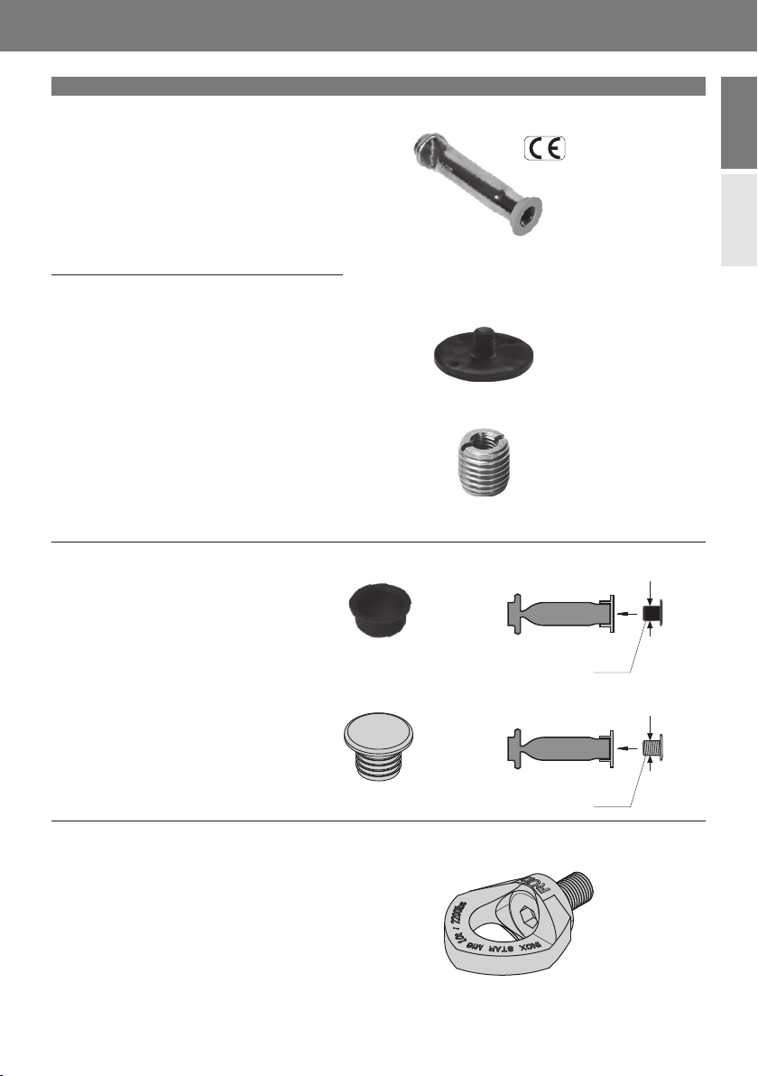
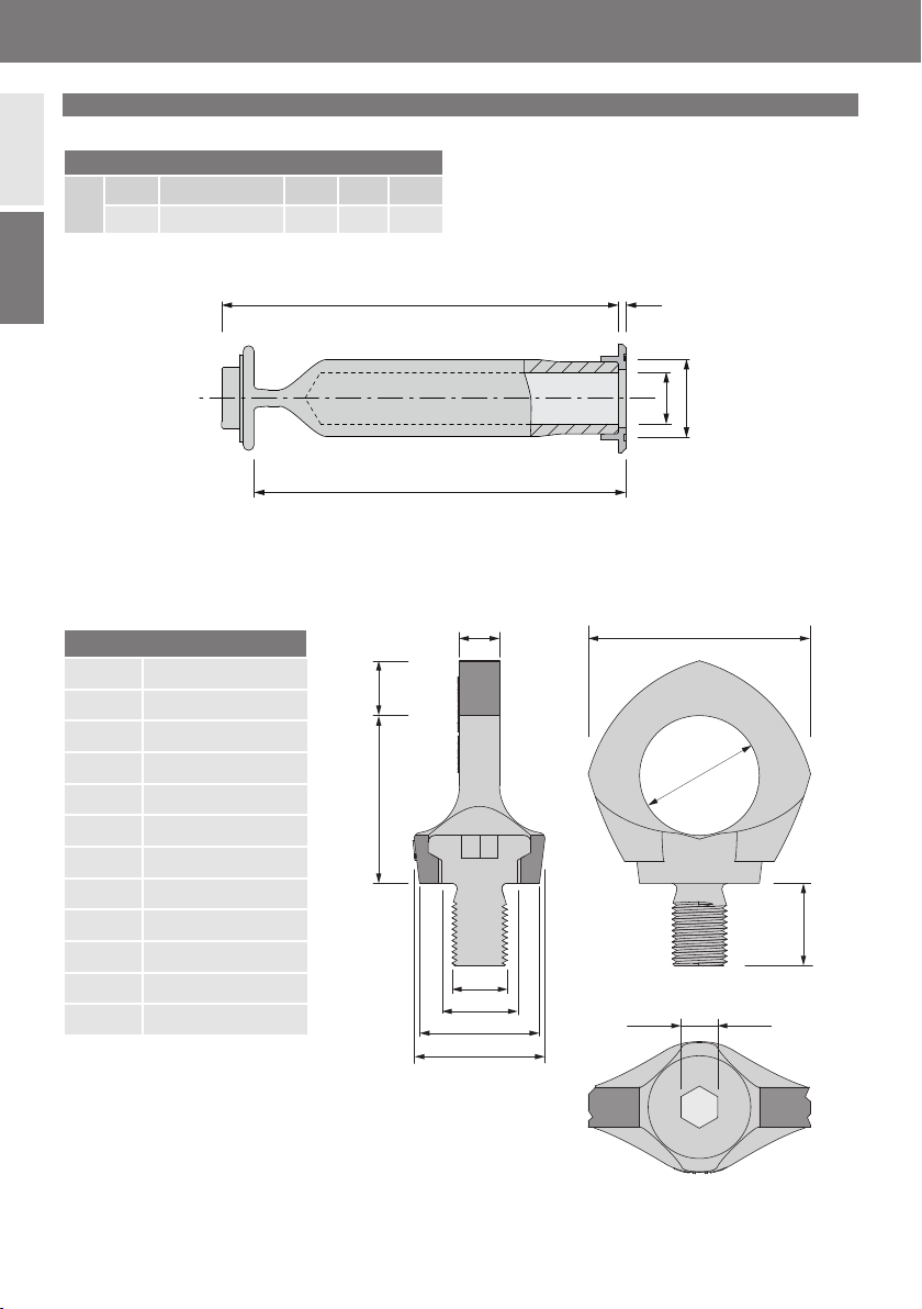
HALFEN PSA Attachment system for (PPE) personal (fall) protection equipment
It is hereby confirmed that the HALFEN PSA Fixing system for (PPE Personal Protective Equipment) has been professionally
installed in compliance with all details and regulations as required in the installation instructions.
(A copy of this document must be given to the client in case of any forthcoming notification requirements by an approved
building authority).
City, date Stamp, signature
Site plan/drawings
Street, road: .........................................................................
Postcode, Zipcode/Town,City:..............................................
Client: ......................................................................
Street, road: .........................................................................
Postcode, Zipcode/Town,City: .............................................
Installation company: ..........................................................
Street, road: .........................................................................
Postcode, Zipcode/Town,City: .............................................
Details/Installation parameters
Component: ........................................................................
Component thickness: .........................................................
Axial spacing: .......................................................................
Building: .............................................................................
Floor: ..................................................................................
Contact: ...............................................................................
Phone/e–mail: .....................................................................
Installer: .............................................................................
Phone/e–mail: .....................................................................
Concrete strength: ...............................................................
Edge distance: .....................................................................
Reinforcement: ....................................................................
Project/location: .....................................................................................................................................................................
Installation documentation

A
t
t
a
c
h
m
e
n
t
f
o
r
F
a
l
l
P
r
o
t
e
c
t
i
o
n
m
a
x
.
2
P
e
r
s
.
9
© 2020 · INST_PSA 11/20 · www.halfen.com
Deutsch English
HALFEN PSA Montageanleitung
Anwendungsgebiet
HALFEN PSA ist ein Anschlagsystem
zur Befestigung einer persönlichen
Schutzausrüstung (PSA) zum Schutz
gegen Absturz gemäß DIN EN 795
und CEN/TS 16415.
An einem Anschlagpunkt können bis
zu 2 Personen fixiert werden, um
Bau-, Montage- und Wartungsarbeiten
in Sicherheit durchzuführen.
Das HALFEN PSA Anschlagsystem be-
steht aus folgenden Komponenten:
DEMU Hülsenanker T-FIXX
M16x110 (Edelstahl A4) als baulich
dauerhaft (im Beton) verankertes
Befestigungsmittel, zugelassen ge-
mäß ETA-13/0222; mit aufgesteck-
tem Datenclip zur Kennzeichnung
als PSA
Ringschraube RUD PSA Inox Star
M16 als Anschlagpunkt (Anschlag-
einrichtung) einer PSA
Die Eignung des Systems wurde im
Hinblick auf die statische Belastbar-
keit durch die Prüf- und Zertifizie-
rungsstelle DGUV Test (Fachbereich
persönliche Schutzausrüstungen)
nachgewiesen.
Beide Komponenten des HALFEN PSA Anschlagsystems (Hülsenanker T-FIXX und Ringschraube) sind aus nichtrostendem
Edelstahlmaterial gefertigt.
Dadurch ist neben dem Einsatz unter trockenen Bedingungen auch der Einsatz im Freien, d. h. unter Witterungseinflüssen in
Außenatmosphäre möglich.
Ausführung / Korrosionsschutz
Datenclip zur Kennzeichnung des
Hülsenankers als Personensicherung
Passende wiederverwendbare
Ringschraube aus Edelstahl
ist separat erhältlich:
RUD PSA INOX STAR M16
(Bestell-Nr.: 0742.260-00001)
Zugelassener Hülsenanker aus
Edelstahl:
DEMU T-FIXX® M16, A4,
ETA-13/0222
(Bestell-Nr.: 0020.270-00508)
ETA-13/0222
Komponenten:

Hülsenanker T-FIXX M16x110 (A4)
Lth
ef dnom b
mm 110 2,0 (Datenclip) 101,3 16 21,3
Ringschraube Inox Star M16
A49mm
B17mm
C15mm
D35mm
E36mm
G38mm
K65mm
L24mm
M16mm
N10mm
S24mm
Gewicht 310 g
10 © 2020 · INST_PSA 11/20 · www.halfen.com
Deutsch English
HALFEN PSA Montageanleitung
Lt
hef
b
dnom
K
D
L
N
B
C
M
S
E
G
A
Abmessungen

Beanspruchbarkeit
Anschlagsystem Unterkonstruktion FRd [kN] Maximale Anzahl Benutzer Beanspruchung
HALFEN PSA Bewehrter Normalbeton
(gerissen, ungerissen) 10,5 2 In alle Richtungen
Einbauparameter
hnom [mm] hmin [mm] cmin [mm] smin [mm] Betongüte
112,0 150,0 175,0 350,0 ≥ C 30/37
11
© 2020 · INST_PSA 11/20 · www.halfen.com
Deutsch English
HALFEN PSA Montageanleitung
Bauteilanforderungen / Tragfähigkeit / Bewehrung
Der Nachweis der lokalen Lasteinleitung der HALFEN PSA bzw. des Hülsenankers T-FIXX M16x110 (A4) ist durch die
ETA-13/0222 erbracht.
Der Nachweis des Bauwerks (Unterkonstruktion) ist unter Berücksichtigung der zu verankernden Lasten durch den verant-
wortlichen Planer zu führen.
Bemessungswerte der Einwirkungen:
Bei der unmittelbaren Befestigung persönlicher Schutzausrüstungen gegen Absturz an den Anschlageinrichtungen gilt nach
DIN 4426 für die erste Person eine charakteristische Einwirkung von FEk = 6 kN und für jede weitere Person eine Erhöhung
von FEk = 1 kN / Person.
Zur Ermittlung der Bemessungswerte der Einwirkungen FEd sind die charakteristischen Werte der Einwirkungen mit einem
Teilsicherheitsbeiwert γF= 1,5 zu multiplizieren:
1 Person: FEd = FEk x γF= 6 kN x 1,5 = 9,0 kN
2 Personen: FEd = FEk x γF= (6 + 1) kN x 1,5 = 10,5 kN
Einbauparameter:
Die Mindestanforderungen an Bauteildicke (hmin), Randabstand (cmin), Achsabstand (smin) sowie Betongüte
(gemäß EN 206) sind der folgenden Tabelle zu entnehmen.
Beim Einbau in gerissenem Beton (Zugzone) ist unter planmäßiger Zugbelastung eine (Zulage-) Bewehrung zur Aufnahme
der Spaltkräfte anzuordnen.
Der erforderliche Bewehrungsquerschnitt Askann beispielsweise mit Hilfe der HALFEN Bemessungs-Software für
DEMU Hülsenanker ermittelt werden.
Eine Zulagebewehrung als Oberflächenbewehrung im Bereich des Einbauteils in Form einer Mattenbewehrung mit minde-
stens 3 Stäben je Richtung und einem Stababstand a ≤ 150 mm, z.B. Q188 (As= 1,88cm²/m) nimmt die Spaltzugkräfte für
den Einsatzfall PSA sicher auf.
Bewehrung zur Aufnahme von Spaltzugkräften:

a
b
c
M16
12 © 2020 · INST_PSA 11/20 · www.halfen.com
Deutsch English
HALFEN PSA Montageanleitung
Hinweise
Für sauberen Verbund zwischen Hülsenanker und Beton ist sicherzustellen, dass der Anker nicht mit Fremdkörpern,
Öl usw. verschmutzt ist.
Beton sorgsam einbringen. Direkten Kontakt zwischen Rüttler und Anker vermeiden.
Zusätzliches Anrödeln der Anker an die Bewehrung ist zu empfehlen.
Die Hülsenanker für PSA werden oberflächenbündig eingebaut.
Haltescheiben unmittelbar nach dem Ausschalen herausdrehen.
Einbau des Hülsenankers als Anschlagsystem für PSA
2.) Vorbereitung zur Montage 3.) Einschrauben der PSA Ringschraube
Fall A
mit Kunststoff-Haltescheibe
Schalung entfernen,
Haltescheibe herausdrehen
Haltescheibe
Typ 2275
Fall B
mit Sechskantschraube
Fall C
mit Gewindeadapter und Sechskantschraube
Gewindeadapter
Typ 2600
Sechskantschraube herausdrehen,
Schalung entfernen Einschrauben der
PSA Ringschraube
a) Sechskantschraube herausdrehen,
b) Schalung entfernen,
c) Gewindeadapter herausdrehen
1.) Befestigung an der Schalung
M8

!
Tinst = 60 Nm
36mm
0mm
− 40°C
+80°C
13
© 2020 · INST_PSA 11/20 · www.halfen.com
Deutsch English
HALFEN PSA Montageanleitung
Vor jeder Benutzung der PSA ist sicherzustellen, dass das Gewinde der Ring-
schraube vollständig im Hülsenanker T-FIXX eingedreht ist (von außen kein
Gewindegang mehr sichtbar).
Die zusätzlichen Hinweise aus der Betriebsanleitung für die rostfreie Ring-
schraube RUD PSA Inox Star M16 sind zu beachten.
Temperatureinsatztauglichkeit: −40°C bis +80°C
Es wird empfohlen, bei Nichtgebrauch der Ankerstelle, den Hülsenanker mit
einem Verschlussstopfen zu verschließen.
Nach der Benutzung der PSA (temporärer Einsatz) kann die Ringschraube
wieder herausgedreht werden.
Verwendung als dauerhaft angebrachte PSA:
Anziehen der Schraube im Hülsenanker mittels gekröpftem Steckschlüssel
und Drehmomentschlüssel unter Aufbringung eines Anzugsmoments
Tinst = 60 Nm. Als zusätzliche Sicherung ggf. ein flüssiges Schraubensiche-
rungsmittel (Loctite o. ä.) verwenden.
Verwendung als temporär angebrachte PSA:
Handfestes Anziehen der Schraube im Hülsenanker mittels Sechskant-
Schraubendreher (Inbusschlüssel).
Es ist sicherzustellen, dass eine plane Anschraubfläche für die Ringschraube
am Beton vorhanden ist. Der Durchmesser der anliegenden Fläche der Ring-
schraube RUD PSA Inox Star M16 beträgt D = 36,0 mm.
Der Datenclip wird zusammen mit dem Anker im Beton eingebaut und muss
nach dem Ausschalen gut sichtbar bleiben (zur dauerhaften Kennzeichnung
als PSA).
Die Montage muss durch Fachpersonal erfolgen, das auf dem Gebiet ausrei-
chend Erfahrung vorweisen kann.
Das HALFEN PSA Anschlagsystem darf nur als Anschlagpunkt für persönliche
Schutzausrüstungen zum Schutz gegen Absturz benutzt werden. Die Verwen-
dung zu Transport- oder Dauerbefestigungszwecken ist nicht erlaubt.
Verwendung / Allgemeine Hinweise

2244
dnom
6315
dnom
14 © 2020 · INST_PSA 11/20 · www.halfen.com
Deutsch English
HALFEN PSA Montageanleitung
Gewindeadapter
Typ 2600
dnom = M16,
dBSchraube = M8
Bestell-Nr. 0021.060-00002
Haltescheibe
Typ 2275 (h= 2 mm)
dnom = M16
Bestell-Nr. 0021.090-00003
Verschlussstopfen (ohne Lamellen)
Artikelbezeichnung: 2244 – M16
Material: Kunststoff
Farbe: schwarz
Bestell-Nr: 0021.030-00005
Verschlussstopfen (mit Lamellen)
Artikelbezeichnung: 6315 – 16
Material: Kunststoff
Farbe: lichtgrau
Bestell-Nr: 0741.130-00003
Hilfsmittel zur Befestigung des T-FIXX an der Schalung:
Hülsenanker T-FIXX®
T-FIXX®- M16 × 110 A4 - FP
Farbe Datenclip: lichtgrau
Bestell-Nr. 0020.270-00508
Montagekomponenten und Bestellnummern
RUD PSA-INOX-STAR-Ringschraube M16 (7996757)
Anschlagpunkt 360° drehbar
Geprüft und zertifiziert durch den Fachbereich PSA der
DGUV, PSA-INOX-STAR aus rostfreiem Edelstahl, Farbe
gelb
Bestell-Nr: 0742.260-00001
Ringschraube

15
© 2020 · INST_PSA 11/20 · www.halfen.com
Deutsch English
HALFEN PSA Montageanleitung
Muster für die Montagedokumentation
HALFEN PSA Anschlagsystem für persönliche Schutzausrüstung gegen Absturz
Hiermit wird bestätigt, dass das HALFEN PSA System für persönliche Schutzausrüstung hinsichtlich aller Einzelheiten fachge-
recht und unter Einhaltung aller Bestimmungen gemäß Montageanleitung montiert wurde.
(Diese Bescheinigung ist dem Bauherrn als Kopie zur ggf. erforderlichen Weitergabe an die zuständige Bauaufsichtsbehörde
auszuhändigen)
Ort, Datum Stempel, Unterschrift
Lageskizze/Einbauplan:
Straße: .................................................................................
PLZ/Ort: ..............................................................................
Auftraggeber: ......................................................................
Straße: .................................................................................
PLZ/Ort: ..............................................................................
Montagefirma: ....................................................................
Straße: .................................................................................
PLZ/Ort: ..............................................................................
Befestigungsdetails/Einbauparameter
Bauteil: .................................................................................
Bauteildicke: .........................................................................
Achsabstand: .......................................................................
Gebäude: .............................................................................
Etage: ..................................................................................
Kontaktperson: ....................................................................
Telefon/Mail: .......................................................................
Monteur: .............................................................................
Telefon/Mail: .......................................................................
Betongüte: ...........................................................................
Randabstand: .......................................................................
Bewehrung: ........................................................................
Projekt/Baustelle: .....................................................................................................................................................................
Montagedokumentation

© 2020 U-113 – 11/20 PDF 11/20
Imagine. Model. Make.
For more information on the products featured here, please contact Leviat:
Notes regarding this document
© Protected by copyright. The information in this publication is based on state-of-the-art technology
at the time of publication. In every case, project working details should be entrusted to appropriately
qualified and experienced persons. Leviat shall not accept liability for the accuracy of the information
in this document or for any printing errors. We reserve the right to make technical and design changes
at any time. With a policy of continuous product development, Leviat reserves the right to modify
product design and specification at any time.
Leviat.com Halfen.com
For information on certified management systems and standards, see www.halfen.com
Australia
98 Kurrajong Avenue,
Mount Druitt Sydney, NSW 2770
Tel: +61 - 2 8808 3100
Email: info[email protected]
Austria
Leonard-Bernstein-Str. 10
Saturn Tower, 1220 Wien
Tel: +43 - 1 - 259 6770
Email: info.at@leviat.com
Belgium
Borkelstraat 131
2900 Schoten
Tel: +32 - 3 - 658 07 20
Email: info[email protected]
China
Room 601 Tower D,
Vantone Centre
No. A6 Chao Yang Men Wai Street
Chaoyang District
Beijing · P.R. China 100020
Tel: +86 - 10 5907 3200
Email: info.cn@leviat.com
Czech Republic
Business Center Šafránkova
Šafránkova 1238/1
155 00 Praha 5
Tel: +420 - 311 - 690 060
Email: info.cz@leviat.com
Finland
Vädursgatan 5
412 50 Göteborg / Sweden
Tel: +358 (0)10 6338781
Email: info[email protected]
France
18, rue Goubet
75019 Paris
Tel: +33 - 1 - 44 52 31 00
Email: info[email protected]
Germany
Liebigstrasse 14
40764 Langenfeld
Tel: +49 - 2173 - 970 - 0
Email: info.de@leviat.com
India
309, 3rd Floor, Orion Business Park
Ghodbunder Road, Kapurbawdi,
Thane West, Thane,
Maharashtra 400607
Tel: +91 - 22 2589 2032
Email: info[email protected]
Italy
Via F.lli Bronzetti 28
24124 Bergamo
Tel: +39 - 035 - 0760711
Email: info[email protected]
Malaysia
28 Jalan Anggerik Mokara 31/59
Kota Kemuning,
40460 Shah Alam Selangor
Tel: +603 - 5122 4182
Email: info.my@leviat.com
Netherlands
Oostermaat 3
7623 CS Borne
Tel: +31 - 74 - 267 14 49
Email: info[email protected]
New Zealand
2/19 Nuttall Drive, Hillsborough,
Christchurch 8022
Tel: +64 - 3 376 5205
Email: info[email protected]
Norway
Vestre Svanholmen 5
4313 Sandnes
Tel: +47 - 51 82 34 00
Email: info[email protected]
Philippines
2933 Regus, Joy Nostalg,
ADB Avenue, Ortigas Center
Pasig City
Tel: +63 - 2 7957 6381
Poland
Ul. Obornicka 287
60-691 Poznań
Tel: +48 - 61 - 622 14 14
Email: info[email protected]
Singapore
14 Benoi Crescent
Singapore 629977
Tel: +65 - 6266 6802
Email: info[email protected]
Spain
Polígono Industrial Santa Ana
c/ Ignacio Zuloaga, 20
28522 Rivas-Vaciamadrid
Tel: +34 - 91 632 18 40
Email: info.es@leviat.com
Sweden
Vädursgatan 5
412 50 Göteborg
Tel: +46 - 31 - 98 58 00
Email: info[email protected]
Switzerland
Hertistrasse 25
8304 Wallisellen
Tel: +41 - 44 - 849 78 78
Email: info.ch@leviat.com
United Kingdom
A1/A2 Portland Close
Houghton Regis LU5 5AW
Tel: +44 - 1582 - 470 300
Email: info.uk@leviat.com
United States of America
6467 S Falkenburg Rd.
Riverview, FL 33578
Tel: (800) 423-9140
Email: info[email protected]
For countries not listed
Email: info@leviat.com
Table of contents
Languages: