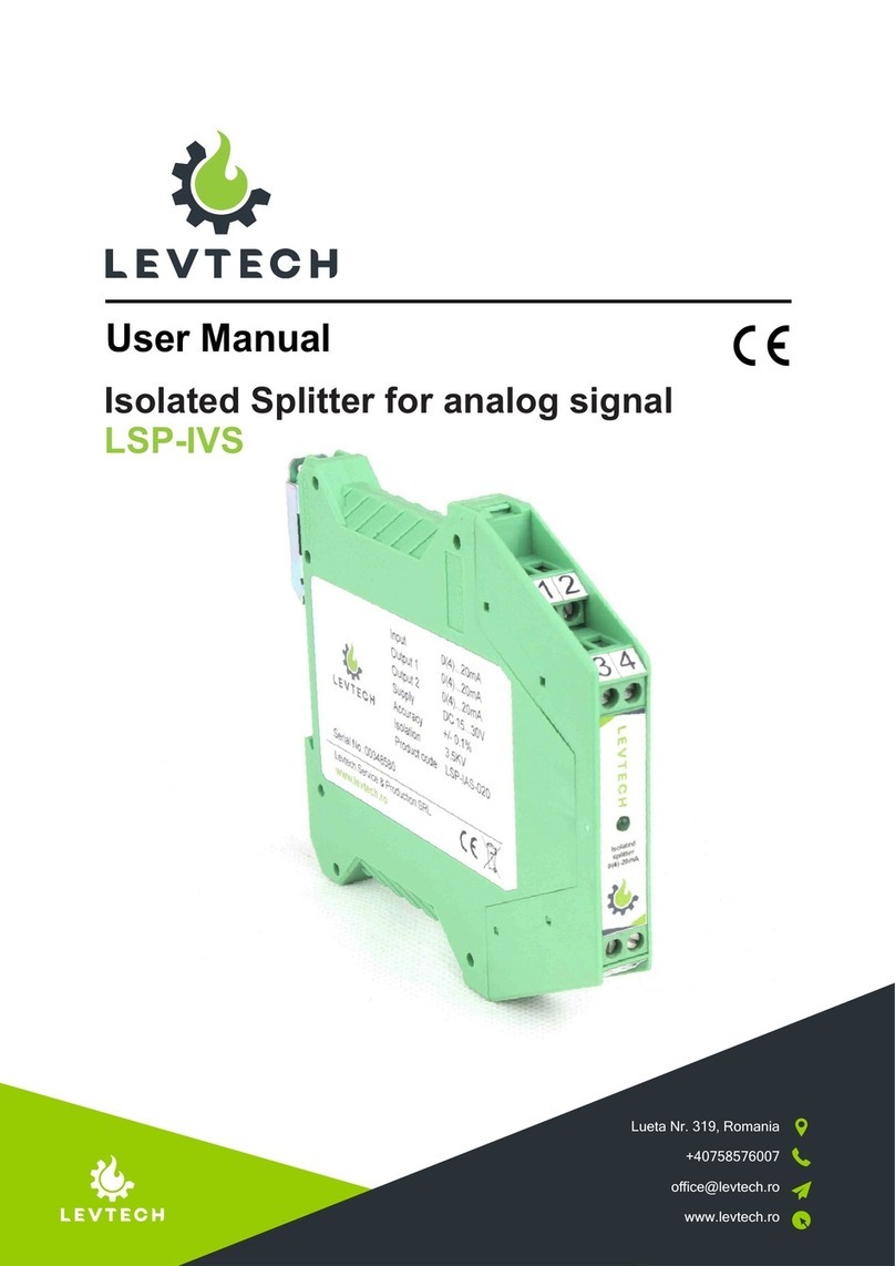
LEVTECH LSP-IV2 Series User manual

User Manual
Lueta Nr. 319, Romania
+40758576007
www.levtech.ro
Galvanic 0-10V or 0-5V Isolator
LSP-IV2

PREFACE......................................................................................................................3
Document Revisions .....................................................................................................4
Approvals......................................................................................................................4
1. INTRODUCTION.......................................................................................................5
1.1. General Information .................................................................................... 5
1.2. Support and Services...................................................................................5
1.3. Disposal Remarks........................................................................................5
2. SAFETY INSTRUCTIONS.........................................................................................6
2.1.Symbols....................................................................................................... 6
2.2. Receipt and unpacking.................................................................................6
2.3. Environment................................................................................................ 6
2.4. Mounting......................................................................................................6
2.5. Cleaning ......................................................................................................7
3. DESCRIPTION..........................................................................................................8
4. FEATURES ...............................................................................................................8
5. INSTALLATION AND WIRING ...................................................................................9
5.1. Installation on TS-35 DIN Rail.......................................................................9
5.2. Connections with Screw Terminals...............................................................9
6. SPECIFICATIONS .................................................................................................. 10
7. CONFIGURATION TYPE AND ORDER CODE........................................................ 10
8. DIMENSIONS......................................................................................................... .11
9. TERMINAL DESIGNATION......................................................................................11
10. ELECTRICAL DIAGRAMS.....................................................................................12
11. APPLICATIONS..................................................................................................... 13
12. OPERATION AND MAINTENANCE......................................................................14
12.1. Operation................................................................................................. 14
12.2. Maintenance ............................................................................................14
13. WARRANTY DISCLAIMER .................................................................................. 14
14. CONTACT INFORMATION ....................................................................................15
Table of Contents

PREFACE
Thank you for selecting our product!
This User Manual contains information needed for proper installation, operation, and
maintenance of your product. A thorough understanding of these simple instructions will
help you get the most of your product.
This document should be read thoroughly, and the safety instructions described in this
manual should be followed carefully. If you have questions or concerns about the
operation and maintenance of this product, please contact our customer support.
If a problem arise with the product, check if you followed the installation steps
correctly. If the problem persists, contact an authorized Levtech dealer or our customer
support.
All information in this User Manual is based on the latest product information available at
the time of printing approval. Levtech reserves the right to make changes at any time
without notice and without incurring any obligation.
Please always keep this manual together with the isolator as a reference to everyone
who uses this product.
3

Approvals
This document requires following approvals:
Date
Version Number
Document Changes
11-03-2021
1.0
Initial draft
13-04-2021
2.0
Overall improvements
15-04-2021
3.0
Application examples added
Name
Title
Levi Mihaly
General Manager
Document Revisions
4
13-05-2021
4.0
Wiring diagram added

5
1.1.
General Information
1.2.
Support and Services
1.3.
Disposal Remarks
Lueta Nr. 319, Romania
+40758576007
www.levtech.ro
1.
INTRODUCTION
This manual is the designated User Manual for the installation, safe operation, and
maintenance of your product. It is divided into nine chapters covering general
information, safety instructions, how to safely install and operate the product,
maintenance, warranty, and contact information.
All personnel involved in the installation, operation, and maintenance of this equipment
should read and understand this manual, particularly its safety instructions. Substandard
performance and longevity, property damage, and personal injury may result from not
knowing and following these instructions.
In order to ensure long product life, Levtech recommends that you utilize the product and
perform maintenance by correctly following the instructions described in this guide. The
manufacturer’s warranty does not cover any damage resulting from the neglect of these
instructions.
Levtech assumes no liability for damage caused by operation contrary to what is
specified in this operating manual.
For information about further questions that are not answer in this manual, additional
materials, and support, please contact:
DO NOT dispose of the product with domestic waste!
Electronic devices have to be disposed of according to the regional directives on
electronic and electric waste disposal. In case of further questions, please consult your
supplier. The supplier may take care of proper disposal.

6
2.2.
Receipt and unpacking
2.3.
Environment
2.4.
Mounting
2.
2.1.
Symbols
WARNING
CAUTION
NOTICE
This symbol indicates information that, if ignored, could result possibly in
personal injury or even death due to incorrect handling.
This symbol indicates information that, if ignored, could possibly result in
personal injury or physical damage due to incorrect handling.
Indicates information considered important, but not hazard-related.
Unpack the device without damaging it and check whether the device type corresponds
to the one ordered. The packing should always follow the device until this has been
permanently mounted.
Avoid direct sunlight, dust, high temperatures, mechanical vibrations and shock, and rain
and heavy moisture.
Only technicians who are familiar with the technical terms, warnings, and
instructions in the manual and who are able to follow these should connect the
device.
Mounting and connection of the device should comply with national legislation for
mounting of electric materials, i.e. wire cross section, protective fuse, and location.
Descriptions of input / output and supply connections are shown in this installation
guide and on the side label.
Use this device only in accordance with this instruction manual, as well as all
applicable local and national laws and regulations. Only allow this device to be
installed, operated, maintained, repaired, etc. by others who have also read and
understood the user manual.
Do not allow minors, untrained personnel, or personnel suffering from physical or
mental impairment that would affect their ability to follow this manual to install,
operate, maintain, or repair this device.
Any untrained personnel who might be near the device while it is in operation
MUST be informed that it is dangerous and fully instructed on how to avoid injury
during its use.
SAFETY INSTRUCTIONS

7
WARNING
CAUTION
2.5.
Cleaning
WARNING
To avoid the risk of electric shock and fire, the safety instructions of this guide
must be observed and the guidelines followed.
When disconnected, the device may be cleaned with a cloth moistened with distilled
water.
The specifications must not be exceeded, and the device must only be applied
as described in the following.
Do not use the device near water or moisture.
Do not install near any heat sources such as radiators, stoves or other heaters
that produce heat.
To prevent ignition of the explosive atmospheres, disconnect power before
servicing and do not separate connectors when energized and an explosive
gas mixture is present.
Do not mount or remove devices from the power rail when an explosive gas
mixture is present.
Before the commissioning of the device, this installation guide must be
examined carefully, and only qualified personnel (technicians) should install
this device.
If the equipment is used in a manner not specified by the manufacturer, the
protection provided by the equipment may be impaired.
To avoid the risk of explosion due to electrostatic charging of the enclosure, do
not handle the units unless the area is known to be safe, or appropriate safety
measures are taken to avoid electrostatic discharge.

4.
FEATURES
3.
DESCRIPTION
Three way isolated
3500VDC Isolation
TS-35 DIN rail mounting
+/-0.1% accuracy
Ip40 case
Screw terminals
Power indicator LED
0-10V or 0-5V analog input and output
Factory calibrated
Made in EU
The LSP-IV2 isolator is designed to make galvanic isolation between the transmitter
and the processing unit (PLC). This isolator is a 3 point galvanic isolator, which
means that the input, output and the power supply is separated from each other.
This instrument is suitable for any industrial application where 0-10V or 0-5V analog
signal is used. The module ensures 3500VDC isolation and reduces the impact of
interferences and ground potential differences. The isolators has to be ordered
according to the input type. They are widely used in automation systems where the field
devices are connected to the PLC on 0-10V or 0-5V analog signals and there are
potential differences.
8

5.2.
Connections with Screw Terminals
5.1.
Installation on TS-35 DIN Rail
Inserting the Module in the Rail:
Removing the Module in the Rail:
5.
INSTALLATION AND WIRING
The module is designed to be installed, in a vertical position, on TS-35 DIN rail. For the
best module performance and duration, avoid placing objects that could obstruct the
ventilation. Never install the modules near heat sources.
1) Attach the module in the lower part of the rail, as shown in the left figure below.
2) Press the module upwards.
1) Apply leverage using a screwdriver, as shown in the right figure below.
2) Press the module downwards.
9
The module has been designed for screw-type terminal electrical connections. Proceed
as follows to make the connections:
1) Strip the cables by 8mm.
2) Insert a screwdriver in hole, unscrewing the screw.
3) Insert the cable in the round hole.
4) Again, use the screwdriver to tight the screw.
5) Remove the screwdriver and make sure that the cable is tightly fastened in the
terminal.
0,2...2,5 mm²
8 mm

6.
SPECIFICATIONS
Input
Input Signal
Direct Voltage
Output
Output Signal
Direct Voltage
Output Range
0-10V or 0-5V
Output Resistance
>1KΩ
Number of outputs
1
Power Supply
Supply Voltage
12 ~ 30VDC
Current Consumption
25mA
Reverse-Polarity Protection
Yes
Enclosure
IP Rating
IP40
Dimensions (L x D x H)
114 x 99 x 12.5 mm
Weight
83g
Mounting
TS-35 DIN
Maximum Cable Cross-Section
2.5mm2
(max.)
Enviromental Conditions
Ambient Temperature Range
-10 ~ +60ºC
Storage Temperature Range
-30 ~
+80ºC
Humidity Level
0 ~ 95% RH at 40ºC, no condensation
10
10K
Input Range 0-10V or 0-5V
Input Resistance Ω
Number of inputs 1
General
Output accuracy
0.10%
Limit frequency
100Hz
Response time
0.8ms
Isolation Voltage
400 VRMS
3500VPEAK
Working isolation voltage
7.
Linearity error 0.10%
CONFIGURATION TYPE AND ORDER CODE
Order Code
Input Output 1
LSP-IV2-005
0-10V
0 5V-
LSP-IV2-010
The LSP-IV2 has two different type and the product has to be ordered according to the
analog signal type used in the system. The following table shows the ordering codes for
each model.
0-10V
0 5V-

11
8.
9.
TERMINAL DESIGNATION
IN OUT
34
24VDC
+
-
+
-
+
-
1
2
PS
V
0-5 V
7
8
0-5 V
IN OUT
34
24VDC
+
-
+
-
+
-
1
2
PS
V
0-10 V
7
8
0-10 V
LSP-IV2-005
LSP-IV2-010
1. Negative Signal Input
2. Positive Signal Input
3. Negative Input of the Power Supply
4. Positive Input of the Power Supply
5.Negative Signal Output;
6.Positive Signal Output.
99.0 mm
114.0 mm
12
34
56
78
12.5
mm
DIMENSIONS

12
10.
ELECTRICAL DIAGRAMS
LSP-IV2 Wiring Example:
In the below example a level sensor is connected to a Siemens PLC through the LSP-
IV2-010 galvanic isolator.
24V
Z
Min 1K
Rs
Isolation
15-30V/5V
Rs = 10k
0-10V V 0-10V
2
+ IN
8
+OUT
4
+U
1
- IN
7
-OUT
3
-U
0-10V
-
0 - 10 V OUT
+
RUN/STOP
U57
LOGO_AM2
L+
M
L+
M
I1
M1
U1
I2
M2
U2
LSP-IV2-010
12
3 4
56
78
+U 0 +U 1
GND0 GND1
0 - 10V
0
0-10V
M1
Field device with
active 0-10V
output

13
11.
APPLICATIONS
Example
1:
The device can be used for several applications on industrial automation. It is ideal
for removing errors caused by noise and signal interference, protecting sensitive
equipment such as PLC form potentional hazards. The module has voltage input and
voltage output.
In the below example a level sensor is connected to a Siemens PLC through the
LSP-IV2 galvanic isolator.

14
13.
WARRANTY DISCLAIMER
12.
OPERATION AND MAINTENANCE
12.1.
Operation
12.2.
Maintenance
This isolator requires no user adjustments during commissioning. It comes with
factory calibration ready for use.
If the isolator fails to operate, check for bad connections. In the unlikely event of the
isolator not working, it should be returned to the supplier for repair or replacement.
Levtech suggests a quick check for terminal tightness and general unit condition. Always
adhere to any site requirements for programmed maintenance.
Levtech warrants this product to be free from significant deviations in material and
workmanship for a period of 3 year from date of purchase. If repair or adjustment is
necessary and has not been the result of abuse or misuse, within the 3 year period,
please return-freight-prepaid and the correction of the defect will be made free of
charge. If you purchased the item from our distributors and it is under warranty,
please contact them to notify us of the situation. Levtech Service Department will
determine if the product problem is due to deviations or customer misuse.
Out-of-warranty products will be repaired on a charge basis.
Authorization must be obtained from one of our representatives before returning items
for any reason. When applying for authorization, have the model and serial number
handy, including data regarding the reason for return. For your protection, items must
be carefully packed to prevent damage in shipment and insured against possible
damage or loss.
Levtech will not be responsible for damage resulting from careless or insufficient
packing. A fee will be charged on all authorized returns.
Levtech reserves the right to make improvements in design, construction and
appearance of our products without notice on which the buyer could reasonably have
discovered the alleged defect or breach.
13.1. Return of items

15
WEBSITE
https://www.levtech.ro/
SOCIAL MEDIA
Levtech
COMPANY DATA
@levtech_s_p
@levtechsp
14.
CONTACT INFORMATION
ADDRESS
Lueta Nr. 319
Post Code 537140
Harghita
Romania
LEVTECH SERVICE & PRODUCTION SRL
Fiscal code (CIF): RO35733217
Trade Register: RC J19/134/2016
IBAN: RO39RNCB0152150349440001
BCR BANK
This manual suits for next models
2
Table of contents
Other LEVTECH Protection Device manuals