Lewitt LCT 1040 User manual

LCT 10 4 0
Manual
Check out the
setup video.
lewitt-audio.com/lct-1040-setup

1
Contents
About the LCT 1040 ......................................................................................... 1
What’s included ................................................................................................ 2
Settings and indicators .................................................................................... 4
Connectors ....................................................................................................... 6
Preparing the microphone for recording ......................................................... 7
Stacked remote setup ...................................................................................... 8
Detached remote setup ................................................................................... 10
FAQs ................................................................................................................. 12
lewitt-audio.com/contact
Are you having troubles or
need a ton of nerdy details?
About the LCT 1040
The LCT 1040 is a microphone system with a
comprehensiveset of options to dial in the perfect
sound – from your sweetspot.
It all started with the vision of creating a studio
microphone that allows you to easily adapt the
sound you need for your session without switching
to another microphone.
After ten years of development and with help from
the international audio community, the LCT 1040
brings new levels to your production workflow.
You’ll be more efficient and sound better than
ever before.
The LCT 1040 is a studio condenser microphone
using both, FET and tube circuitry. It is exclusively
built from premium components and features
four distinct all-analog tube characteristics.
Together with the blendable FET circuit, they
allow you to effortlessly find the perfect sound for
your session.
•Gold-sputtered 1" true condenser capsule
•100% analog signal path
•Four distinct all-analog tube characteristics:
Clear, Warm, Dark, Saturated
•Independent FET circuit with dedicated
XLR output
•Both circuits can be seamlessly blended
•Tube and FET microphone in one housing
•Remote control and power supply unit
•Low-cut filters and pre-attenuation settings
•Seamless polar pattern control
•Default/Reverse switch to freely determine the
front of the microphone
•LED status indicators
•E88CC / 6DJ8 tube from JJ Electronics

23
Get your popcorn ready
and simply scan the code
to open the setup video.
lewitt-audio.com/lct-1040-setup
What’s included
Recall Sheets
Custom 10-pin cableMicrophone mount
Power cable
Tube microphone with
1" true condenser
capsule
Front Back Side
Remote control to set
all parameters from
your sweetspot
Magnetic pop filter to
reduce plosives
Shock mount that
reduces low-frequency
rumble and
structure-borne noise
Power supply unit
Register your
product and
extend your
warranty to 10
years for free.
lewitt-audio.com/mylewitt

4 5
Settings and indicators
Tube
Change the tube characteristic.
•Clear: Tube works at technical optimum.
•Warm: Smooth and pleasant high-end.
•Dark: Tamed highs for bright sources.
•Saturated: Rich harmonics and subtle
compression.
Filter
Set the low-cut filter to fit your needs.
Attenuation
Set the right attenuation for your recording
situation.
Circuit
Blend between tube and FET circuit. This ratio will
be sent to the Mix output.
Pattern
Set your polar patterns seamlessly. The notches
indicate standard polar patterns.
LEDs on remote
Power: Indicates that the system is turned on. The
LED turns red in Sleep mode.
Microphone: Microphone is connected.
Operational: Ready to use when the LED is steady.
Blinking indicates that the system needs a few
seconds to be fully operational (after starting up,
changing the pattern, setting attenuation, etc).
LEDs on PSU
Power: System receives power. Red in Sleep.
Remote: Remote is connected.
Microphone: Microphone is connected.
Release button
Press to detach the remote from the PSU. If
properly stacked, remote and PSU hold firmly
together. A click mechanism confirms this.
Default / Reverse
Define which side is set as the front of the
microphone. Default indicates the tube window is
set as the front. Reverse sets the logo as the front.
Default Reverse

6 7
Connectors
Mix
Outputs the mixed
signal set via the Circuit
control: Fully clockwise
provides 100% tube,
fully counterclockwise
100% FET.
Preparing the microphone for recording
Sleep
Hold to put the system
into sleep mode/wake
it up.
Logo light
Tap to activate/
deactivate the
logo light on the
microphone.
Remote
Connect a standard
3-pin XLR cable to
use the remote in the
detached setup.
Not needed in the
stacked setup.
Microphone
Connect the
microphone via the
included 10-pin cable.
Mount the shock mount onto a stable microphone
stand. Open the fixture of the shock mount. Put
the tube microphone in the shock mount. The
tube window indicates the default front. Lock the
fixture.
Attach the pop filter from below. You will feel when
the magnet snaps it into place.
Connect the microphone to the PSU via the 10-pin
cable. Flip the power switch on the PSU. Check
the status LEDs and wait until 'Operational' stops
blinking.
Now, the microphone system has reached its full
sensitivity and you are ready to record.
FET
Outputs the pure FET
signal independently
from the setting on the
Circuit control setting.
The low-cut and
attenuation settings will
still affect the signal.
Power
Turn the system on/off.
Open

8 9
Stacked remote setup
The LCT 1040 consists of three parts: the
microphone, the PSU, and the remote. The remote
is attached to the PSU by default (no cable
needed).
Connect the microphone via the 10-pin cable.
On the right side, you can see how to wire all
parts for the stacked remote setup.
Connect to your preamp,
audio interface, or
mixing console
Standard XLR cable
Custom
10-pin cable
Remote control
stacked to PSU

10 11
Detached remote setup
Push to detach
remote control
from PSU
You can detach the remote from the PSU and
use it without any drawbacks in sound quality.
This is perfect when you have a separate control
and recording room. The connection works via
standard XLR cable and is compatible with your
patchbay (maximum cable length is 150m / 492ft).
If transformers are in the signal path, the
communication between the remote and PSU will
not work. Polarity inversion however is not a
problem.
If you use a half-normalled patch bay, make sure
to insert a cable in the patch-point in the row
below. Otherwise the remote will not receive the
necessary operating voltage.
Tip: If you are not certain if the remote is properly
connected, check the 'Remote' LED on the PSU.
Connect the microphone to the PSU via the
10-pin cable. Connect the PSU to the remote via
standard XLR cable.
Turn on power and check all status LEDs.
Preamp, interface or mixing console

12
FAQs Please note
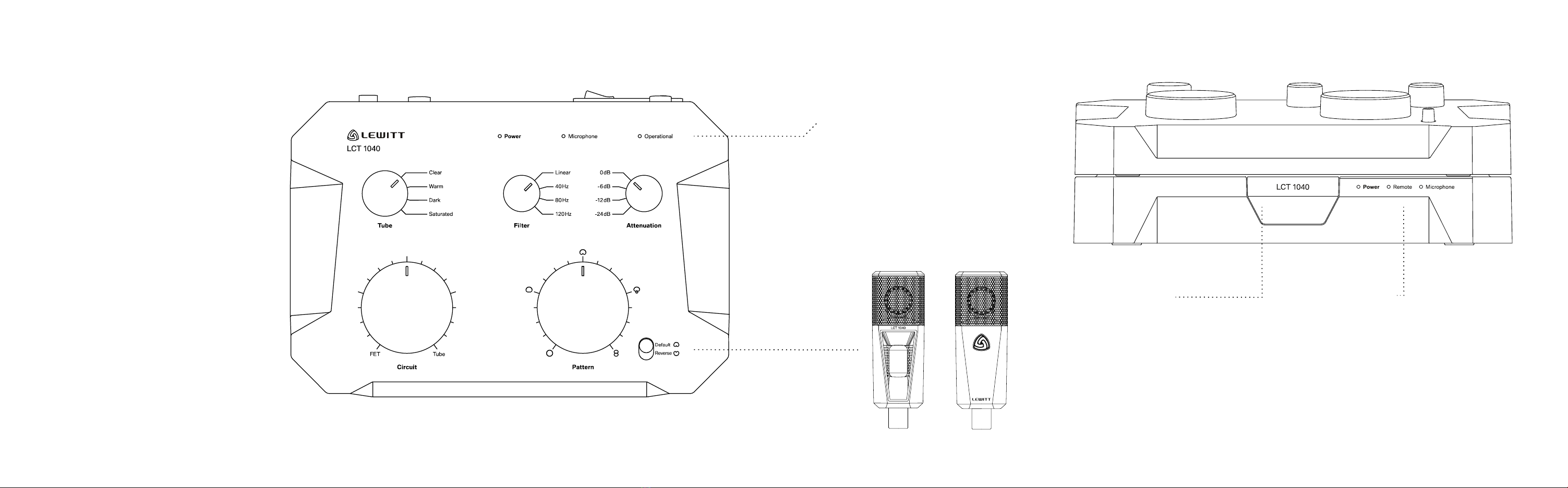
When is the system fully
operational?
The 'Operational' LED on the remote indicates that
the system is ready to use. Once it stops blinking,
the microphone has reached full sensitivity.
Can I damage something when
incorrectly patched?
The PSU sends +24V to the remote, which could
possibly damage other equipment. So please be
careful when patching the remote signal.
Can I damage the system if
cables are un/plugged while
it’s powered?
Technically, no. For the sake of treating your
LCT1040 well, please refrain from doing it.
What kind of tube is inside?
After months of testing, we settled on the
E88CC / 6DJ8 from JJ Electronics.
Can I change the tube?
The LCT 1040 is an extremely fine-tuned and
calibrated system. We spent months finding the
perfect tube. So, no, please don’t change the
tube. You’ll also void your warranty by doing so.
Where can I find the
specifications for the LCT 1040?
For detailed specifications and the tech graph,
please visit our product page
lewitt-audio.com/lct-1040.
Do I need to hang the mic upside
down due to the heat coming
from the tube?
We tested it. There is no audible difference. Just
position it the way you prefer.
Can I extend the cable between
the remote and the PSU by
combining multiple cables?
Yes, but please make sure they’re not longer
than 150m / 492ft.
Are you using some kind
of 'modeling' for the tube
characteristics?
The signals stay purely in the analog domain.
Only the controls are digital, which gives you the
best of both worlds.
•The capsule is a sensitive, high precision
component. Make sure you do not drop the
microphone from high heights and avoid strong
mechanical stress and force.
•To ensure high sensitivity and the best sound
reproduction possible, avoid exposing it to
moisture, dust or extreme temperatures.
•Do not apply excessive force on the buttons or
the connected cables.
•When disconnecting the microphone cable,
grasp the connector instead of pulling the
cable.
•Do not attempt to modify or open the product,
as doing so will void your product warranty.
•The casing of the LCT 1040 can be cleaned
easily using a wet cloth, never use alcohol or
another solvent for cleaning.
Important Notice!
Only use C13 power cord connected to a socket-
outlet with earthing connection. Do not use any
ground lifting circuits. In case of problems with
electrical hum and interference, first try to change
position, install a mains filter, or try a different
power outlet. If the problem persists please
contact our support. Removing the earthing
connection can have lethal consequences. Only
use indoors, in safe and dry environments. There
are no user-serviceable parts inside the power
supply unit or the microphone, but there are
potentially lethal voltages. If it does not work
correctly, please consult your dealer. Do not open
the unit yourself. Do not use with damaged cables
or after unit has fallen and loose parts or broken
glass can be heard inside. Do not cover the power
supply unit, always leave enough space around it
for proper ventilation.
This equipment has been tested and found to
comply with the limits for a Class B digital device,
pursuant to part 15 of the FCC Rules. These limits
are designed to provide reasonable protection
against harmful interference in a residential
installation. This equipment generates, uses
and can radiate radio frequency energy and, if
not installed and used in accordance with the
instructions, may cause harmful interference
to radio communications. However, there is no
guarantee that interference will not occur in a
particular installation. If this equipment does
cause harmful interference to radio or television
reception, which can be determined by turning
the equipment off and on, the user is encouraged
to try to correct the interference by one or more
of the following measures: Reorient or relocate
the receiving antenna. Increase the separation
between the equipment and receiver. Connect the
equipment into an outlet on a circuit different from
that to which the receiver is connected. Consult
the dealer or an experienced radio/TV technician
for help.
© All rights reserved by
LEWITT GmbH
13

lewitt-audio.com/contact
If you have any further
questions, please get
in touch.
We look forward to
hearing from you.

Table of contents
Other Lewitt Microphone manuals

Lewitt
Lewitt LCT 240 User manual

Lewitt
Lewitt LCT 640 TS User manual

Lewitt
Lewitt MTP 240 DM User manual

Lewitt
Lewitt MTP 440 DM User manual

Lewitt
Lewitt LCT 550 User manual

Lewitt
Lewitt MTP 940 CM User manual

Lewitt
Lewitt MTP 840 DM User manual

Lewitt
Lewitt DGT 650 User manual

Lewitt
Lewitt MTP 340 CMs User manual

Lewitt
Lewitt LCT 450 User manual

Lewitt
Lewitt DTP 640 REX User manual

Lewitt
Lewitt LCT 440 PURE User manual

Lewitt
Lewitt LCT 449 PURE User manual

Lewitt
Lewitt LCT 550 User manual

Lewitt
Lewitt DTP 340 TT User manual

Lewitt
Lewitt LCT 540 Authentica User manual

Lewitt
Lewitt LCT 140 User manual

Lewitt
Lewitt LCT 449 PURE User manual

Lewitt
Lewitt LCT 640 TS User manual

Lewitt
Lewitt MTP 340 CMs User manual