manuals.online logo
Brands
  1. Home
  2. •
  3. Brands
  4. •
  5. Lexing
  6. •
  7. Accessories
  8. •
  9. Lexing LX-PR-S15-Z User manual

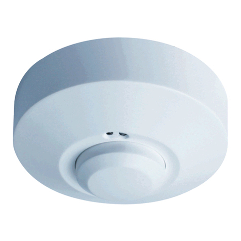
Lexing LX-PR-S15-Z User manual

Protection level: IP20,Class II
Time setting: 8sec to 12min (adjustable)
Detection angle: 360°
Detection range: 1-4m(radii.) (adjustable)
Light-ontrol: 2-2000LUX (adjustable)
Power source: 100-240VAC
Power frequency: 50/60Hz
All loads
:
1200W Max.(220-240VAC)
800W Max.(100-130VAC)
Working temperature: -10°C~+40°C
Specifications
Summary
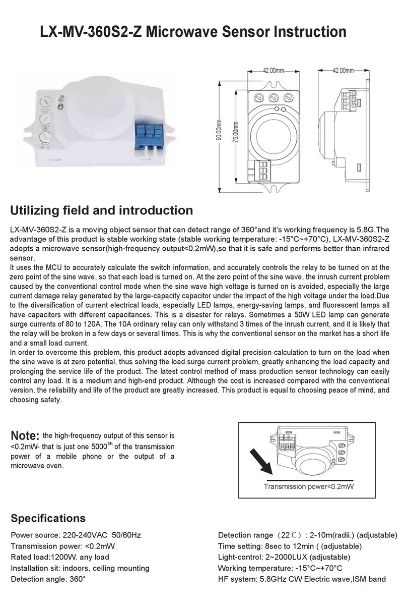
This product is an advanced digitally controlled infrared pyroelectric intelligent sensor product.It uses the MCU
to accurately calculate the switch information, and accurately controls the relay to be turned on at the zero
point of the sine wave, so that each load is turned on. At the zero point of the sine wave, the inrush current
problem caused by the conventional control mode when the sine wave high voltage is turned on is avoided,
especially the large current damage relay generated by the large-capacity capacitor under the impact of the
high voltage under the load.Due to the diversification of current electrical loads, especially LED lamps,
energy-saving lamps, and fluorescent lamps all have capacitors with different capacitances. This is a disaster
for relays. Sometimes a 50W LED lamp can generate surge currents of 80 to 120A. The 10A ordinary relay can
only withstand 3 times of the inrush current, and it is likely that the relay will be broken in a few days or several
times. This is why the conventional sensor on the market has a short life and a small load current.
In order to overcome this problem, this product adopts advanced digital precision calculation to turn on the load
when the sine wave is at zero potential, thus solving the load surge current problem, greatly enhancing the
load capacity and prolonging the service life of the product. The latest control method of mass production
sensor technology can easily control any load. It is a medium and high-end product. Although the cost is
increased compared with the conventional version, the reliability and life of the product are greatly increased.
This product is equal to choosing peace of mind, and choosing safety.
LX-PR-S15-Z Infrared Sensor Instruction
Sensor information
Height of installation2.5-4.5m
2.5-4.5m
4m4m 1m 1m
Detection range(22℃)
360°
Detection angle
Applications
For example, the application in lightings, only if making connection as below shown can you change the
common lightings into auto-sensing lightings.
19mm43.7mm
Ø50mm
Ø68mm
SENS TIME LUX
You can install one or more inside the ceiling or
floor to control the whole passageway.
Friendly reminder: when installing two or more
Infrared sensors together, you are required to
keep 4 meters one from another, otherwise the
interference among them will lead to error
reaction.
Nonmetals
When installed inside the ceiling or floor, the sensor fails to
distinguish the ambient light intensity automatically.
Connect N, L with power;
Connect N ’, L with load.’
L
L
N
input~
output~
Sensor
Load
Setting manner one:potentiometer
It may take times to adjust values before they satisfy your need.
Detection range setting(sensitivity)
1-4m
Note: the above detection range is gained in the case of a person who is between 1.6m~1.7m
tall with middle figure and moves at a speed of 1.0~1.5m/sec. if person’s stature, figure and
moving speed change, the detection range will also change.
Notice: when using this product, please adjust the sensitivity (detection range) to an
appropriate value but the maximum to avoid the abnormal reaction caused by the easy
detection of the wrong motion by the blowing leaves & curtains, small animals or the
interference of power grid & electrical equipment. All the above mentioned will lead to the
error reaction. When the product does not work normally, please try to lower the sensitivity
appropriately, and then test it.Human movement will cause the sensor induction,so when you
under the function testing,please leave the induction region and don't make movement to
prevent the sensor continuous work.
Friendly reminder: when installing two or more microwaves together, you are required to
keep 4 meters one from another, otherwise the interference among them will lead to error
reaction.
Detection range is the term used to escribe the radii of the roughly circle casting on the
ground when installed at the height of 2.5 m. To turn the knob fully anti-clockwise is the
minimum range, fully clockwise is the maximum.
N LL’
Light-control setting
2-2000LUX
Time setting
8sec-12min
It is mainly for the adjustment of the delay time from the moment the signal detected and light
auto-on till the light auto-off. You can define the delay time to your practical need. But you’d
better lower the delay time for the sake of energy saving, since the microwave sensor has the
function of continuous sensing, that is, any movement detected before the delay time
elapses will re-start the timer and the light will keep on only if there is human in the detection
range.
Note: please don’t adjust the three functional knobs to excess. That is because the three
functional knobs were connected to the components directly, there is a small stopper in each
of the three components, when you adjust the knobs from start to end, the excessive turn will
damage the stopper,and lead to the 360°non-stop turn around. The adjust range limit is
270°, please do pay attention to this.
It can be defined from 8 seconds(turn fully anti-clockwise) to 12minutes(turn fully
clockwise). Any movement detected before this time elapses will re-start the timer. It is
recommended to select the shortest time for adjusting the detection range and for
performing the walk test.
NOTE:When the light be auto off,it will take 1 second before the sensor is ready to detect
another movement,that is,only signal detected 1 seconds later can the light be auto-on.
It can be defined in the range of 2~2000 LUX. To turn the knob fully anti-clockwise is
about 2 lux,fully clockwise is about 2000 lux.When adjusting the detection zone and
performing the walk test in daylight,you should turn the knob fully clockwise.




Installation
Switch off the power.
Set threaded tubes into the power cord and control line.
Connect the power and the load with the sensor according to the connection-line diagram.
Turn the knobs to the ideal conditions
(Please define the settings as per the above SETTING MANNER ONE part mentioned.).
50mm
Warning!
1、Being installed on the rocking object will lead to error reaction.
2、The shaking curtain blown by wind will lead to error reaction. Please select the suitable place to install.
3、Being installed where the traffic is busy will lead to error reaction.
4、The sparks produced by some equipment nearby will lead to error reaction.
The following situations will lead to error reaction.
Fault and the solution
The load fails to work.
Light-illumination is set incorrectly.Adjust the setting of the load.
Change the load.
Turn the power on.
Check the settings of the
detection area.
Re-adjust the installation place.
Check the settings of the
detection area.
Check the settings of the
detection area.
The load is broken.
The power is off.
There is a continuous signal in the region of the detection.
Moving signal is detected by the sensor (movement
behind the wall, the movement of small objects, etc.)
The lamp isn't installed well so that sensor fails to
detect reliable signals.
The motion speed is too fast or the defined detection
area is too small.
Fault Failure cause Solution
The load works all the time.
The load works when there is
no motion signal detected.
The load fails to work when
there is motion signal detected.
● Please confirm with prefessional installation.
● For safety purposes, please cut off power before installation and removal operations.
● Any losses caused by improper operation,the manufacturer does not undertake any
responsibility.
Warning!
This manual is the content of the product programming, we will not notify you separately. It
is strictly forbidden to copy the contents of the instruction manual for any other purpose
without the permission of the company.

Other Lexing Accessories manuals

Lexing LX-SLL136L User manual

Lexing

Lexing LX-SLL136L User manual

Lexing LX-180GS12 User manual

Lexing

Lexing LX-180GS12 User manual

Lexing -MV-128LED-D User manual

Lexing

Lexing -MV-128LED-D User manual

Lexing LX-MV-360S18 User manual

Lexing

Lexing LX-MV-360S18 User manual

Lexing LX-MV-360S15A-Z User manual

Lexing

Lexing LX-MV-360S15A-Z User manual

Lexing LX-PR-M18Z User manual

Lexing

Lexing LX-PR-M18Z User manual

Lexing LX-MV360S2-IR Series User manual

Lexing

Lexing LX-MV360S2-IR Series User manual

Lexing LX-PR-28F User manual

Lexing

Lexing LX-PR-28F User manual

Lexing LX16C User manual

Lexing

Lexing LX16C User manual

Lexing LX-MV-360S2-Z User manual

Lexing

Lexing LX-MV-360S2-Z User manual

Lexing LX-MV-360S2-A-Z User manual

Lexing

Lexing LX-MV-360S2-A-Z User manual

Lexing LX-MV-360S13B User manual

Lexing

Lexing LX-MV-360S13B User manual

Lexing LX-MV-360S13A User manual

Lexing

Lexing LX-MV-360S13A User manual

Lexing LX-PR-65S User manual

Lexing

Lexing LX-PR-65S User manual

Lexing LX-PR-29B User manual

Lexing

Lexing LX-PR-29B User manual

Lexing LX-PR-29A User manual

Lexing

Lexing LX-PR-29A User manual

Lexing LX-MV-360S15B-Z User manual

Lexing

Lexing LX-MV-360S15B-Z User manual

Lexing LX-MV-360S1 User manual

Lexing

Lexing LX-MV-360S1 User manual

Lexing LX16C-Z User manual

Lexing

Lexing LX16C-Z User manual

Lexing LX-PR136A User manual

Lexing

Lexing LX-PR136A User manual

Lexing LX-AL9 User manual

Lexing

Lexing LX-AL9 User manual

Popular Accessories manuals by other brands

Chamberlain Protector 87LM manual

Chamberlain

Chamberlain Protector 87LM manual

Toa ZP-001T Specifications

Toa

Toa ZP-001T Specifications

Sony LocationFree LF-B20 quick start guide

Sony

Sony LocationFree LF-B20 quick start guide

Propel Trampolines PTSA15-108 user manual

Propel Trampolines

Propel Trampolines PTSA15-108 user manual

Lightolier 1001HL specification

Lightolier

Lightolier 1001HL specification

SunSetter Motorized Series Owner's Manual & Installation Instructions

SunSetter

SunSetter Motorized Series Owner's Manual & Installation Instructions

Rielta PIRS-1-2V installation guide

Rielta

Rielta PIRS-1-2V installation guide

Marport Trawl Speed Service manual

Marport

Marport Trawl Speed Service manual

Dancover AW148011 manual

Dancover

Dancover AW148011 manual

BEA Fly manual

BEA

BEA Fly manual

Yeelight YLYD01YL user manual

Yeelight

Yeelight YLYD01YL user manual

BaiYou Electronic BY213-C021-W installation instructions

BaiYou Electronic

BaiYou Electronic BY213-C021-W installation instructions

Ryobi 4070333 Operator's manual

Ryobi

Ryobi 4070333 Operator's manual

Sports Tutor Tennis Tower owner's manual

Sports Tutor

Sports Tutor Tennis Tower owner's manual

NAPCO ADVANCED ADAPTIVE C-200AP installation instructions

NAPCO

NAPCO ADVANCED ADAPTIVE C-200AP installation instructions

Lippert Components Solera Classic Installation and owner's manual

Lippert Components

Lippert Components Solera Classic Installation and owner's manual

KERUI KR-M623 quick start guide

KERUI

KERUI KR-M623 quick start guide

Distech Controls EC-Multi-Sensor-BLE installation guide

Distech Controls

Distech Controls EC-Multi-Sensor-BLE installation guide

manuals.online logo
manuals.online logoBrands
  • About & Mission
  • Contact us
  • Privacy Policy
  • Terms and Conditions

Copyright 2025 Manuals.Online. All Rights Reserved.