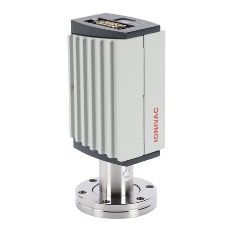
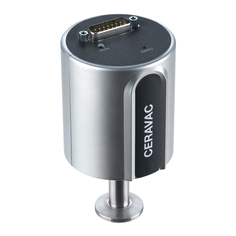
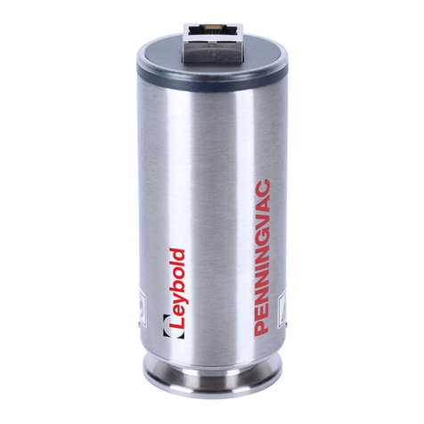
LEYBOLD PENNINGVAC PTR 90 N User manual

1 300544652_002_C1 - 11/2016 - © Leybold
PENNINGVAC Transmitter
PTR 90 N
Operating Manual 300544657_002_C1
Part Numbers:
230070V02
230085V02
230071V02
230072V02
230088V02
230089V02

2 300544652_002_C1 - 11/2016 - © Leybold
Contents
Safety Information 3
0.1 Symbols used 3
0.2 Personnel Qualifications 3
0.3 General safety information 3
0.4 Liability and Warranty 5
Unpacking 6
Description 7
2.1 Technical Data 8
2.2 Dimensions 9
2.3 Accessories and replacement part numbers 11
Transmitter Installation (Mechanical) 12
3.1 Conforming utilization 12
3.2 Non-conforming utilization 12
3.3 Process compatibility 12
3.4 Vacuum connections 13
Transmitter Installation (Electrical) 14
4.1 Input/Output Wiring 15
4.2 Setpoint relays 17
Operations 18
5.1 Pressure output 18
5.2 Cold Cathode Ignition 19
5.3 Analog output 20
5.4 Sensor gas dependence 22
Functions 23
6.1 LED-ring/LED status indicator 23
6.2 Vacuum-zero/full-scale adjustment and setpoint adjustments 24
6.3 User switch adjustments 26
6.4 Integrated touch display 28
FAQ (Frequently Asked Questions) 30
Troubleshooting 32
Maintenance 33
9.1 Cold cathode maintenance 33
Declaration of Contamination 34
Declaration of Conformity 36
Notes 37
Sales and Service 38

3 300544652_002_C1 - 11/2016 - © Leybold
Safety Information
0.1 Symbols used
The first two symbols identify other information in this manual that is essential or useful in achieving optimal
performance from the transmitter. The last symbol below is used throughout this manual to further define the safety
concerns associated with the product.
Calls attention to important procedures, practices or conditions.
0.2 Personnel Qualifications
0.3 General safety information
The safety instructions should always be followed during installation and operation of the transmitter.
Pass safety information to all users.
Adhere to the applicable regulations and take the necessary precautions for the process media used.
Consider possible reactions between the materials and the process media.
Consider possible reactions (e.g. explosion) of the process media due to the heat generated by the
product.
Adhere to the applicable regulations and take the necessary precautions for all work you are going to do
and consider the safety instructions in this document.
Before beginning to work, find out whether any vacuum components are contaminated. Adhere to the
relevant regulations and take the necessary precautions when handling contaminated parts.
Safety Precautions:
Failure to read message could result in damage to the equipment.
Refer to manual. Failure to read message could result in personal injury or serious damage to the equipment or
both.
All work described in this document may only be carried out by persons who have suitable technical training and
the necessary experience or who have been instructed by the end-user of the product.
Explosive Environments. Do not use the transmitter in presence of flammable gases or other
explosive environments.
Corrosive Environments. The transmitter is not intended for use in corrosive environments. Refer
to Transmitter installation chapter 3 of this manual. If you need further support please contact
Leybold.
Service and Repair. Do not substitute parts or modify instrument other than described in chapter 9.
Do not install substituted parts or perform any unauthorized modification to the instrument. Return
the instrument to an Leybold Calibration and Service Center for service and repair to ensure all of
the safety features are maintained.
Critical
Attention
Critical
Critical
!
!
!
Caution
!
Skilled personnel

4 300544652_002_C1 - 11/2016 - © Leybold
DANGER: contaminated parts
Contaminated parts can be detrimental to health and environment. Before beginning to work, find
out whether any parts are contaminated. Adhere to the relevant regulations and take the necessary
precautions when handling contaminated parts.
Danger: Magnetic fields
Strong magnetic fields can disturb electronic devices like heart pacemakers or impair their function.
Maintain a safety distance of ≥10 cm between the magnet and the heart pacemaker or prevent the
influence of strong magnetic fields by antimagnetic shielding.
DANGER: Overpressure in the vacuum system 2.5 bar < p < 5 bar
KF flange connections with elastomer seals (e.g. O-rings) cannot withstand such pressures.
Process media can thus leak and possibly damage your health. Use O-ring with an outer centering
ring + 3-part clamping ring (clamping collar).
Caution: vacuum component
Dirt and damages impair the function of the vacuum component. When handling vacuum
components, take appropriate measures to ensure cleanliness and prevent damages.
CE marking The transmitter complies with European standards for CE marking. Refer to
Declaration of Conformity chapter 11 of this manual.
Fuse. The transmitter power supply input has an internal thermal fuse. The fuse is self-recoverable
and should not be changed.
Electrical connections. The transmitter must be properly electrically connected in order to perform
according to the specifications.
Output pins are not protected against wrong electrical connections. Wrong electrical connections
can cause permanent damage to the transmitter or interference to measuring performance.
Refer to electrical connections description in chapter 4 of this manual.
Caution: dirt sensitive area
Touching the product or parts thereof with one's bare hands increases the desorption rate.
Always wear clean, lint-free gloves and use clean tools when working in this area.
Critical
!
Attention
!
!
Attention
!
Critical
Critical
!
Caution
!
!
Caution
!
Caution
!

5 300544652_002_C1 - 11/2016 - © Leybold
0.4 Liability and Warranty
Leybold assumes no liability and the warranty becomes null and void if the end-user or third parties
disregard the information in this document
use the product in a non-conforming manner
make any kind of interventions (modifications, alterations etc.) on the product
use the product with accessories not listed in the product documentation
The end-user assumes the responsibility in conjunction with the process media used. Transmitter failures due to contamination
are not covered by the warranty.

6 300544652_002_C1 - 11/2016 - © Leybold
Unpacking
Before unpacking your transmitter, check all surfaces of the packing material for shipping damage. Inspect for
visible damage. If found, notify the carrier immediately.
Please be sure that your transmitter package contains these items:
1 pcs. PTR 90 N PENNINGVAC Transmitter
1 pcs. English short form manual (P/N: 300544671_002)
1 pcs. German short form manual (P/N: 300544671_001)
1 pcs. Product Inspection and Test Report
1 pcs. Pin for adjusting settings via button (only for P/N: 230085V02, 230071V02, 230072V02,
230088V02).
If any items are missing, please contact Leybold.

7 300544652_002_C1 - 11/2016 - © Leybold
Description
The PTR 90 N PENNINGVAC series vacuum transmitters offer a wide measuring range from 1×10⁻⁸ mbar to 1000
mbar and are based on measurement of thermal conductivity in a small cavity on a MEMS Pirani silicon chip
sensor and cold cathode (CC) ionization current.
Transmitter versions with RS232 digital communication interface (P/N: 230088V02) or EtherCAT digital
communication interface (P/N: 230089V02) can set up transmitter parameters and provide real time pressure
measurement. Please see the Communication Protocol 300544663 (RS232) and 300544664 (EtherCAT) for further
details. Transmitter versions with an Integrated touchscreen display (P/N: 2300085V02) have the possibility to
monitor essential transmitter parameters. Please see chapter 6.4 for further details.
Each transmitter is individually tested throughout the measuring range before leaving the factory. A test report is
included in the package. In addition, each transmitter pressure reading is individually temperature-compensated
within the specified operating temperature range.
The transmitters can be used in a variety of applications as standalone unit or with Graphix controllers (P/N:
230680V01, 230681V01, 230682V01) and the Display controllers (P/N: 230001, 230024, 230025). All
PENNINGVAC transmitters are backward compatible with Graphix, Display and Center controllers.
The transmitters have up to three mechanical relays which can be used for process control, for
example interlocking valves or pumps. The analog voltage output can be interfaced to external analog
equipment for pressure readout or control.
Sensor technology
The transmitters contain two separate sensor elements. The MEMS Pirani (MEMS = Micro-Electro-Mechanical-
System) sensor element is based on measurement of thermal conductivity. The MEMS Pirani sensor consists of a
silicon chip with a heated resistive element forming one surface of a cavity. A cover on top of the chip forms the
other surface of the cavity. Due to the geometry of the sensor, convection cannot take place within the cavity and
consequently the sensor is insensitive to mounting position. Gas molecules are passed by diffusion only to the
heated element where the heat loss of the gas is measured.
The cold cathode inverted magnetron utilizes a high voltage anode, cathode and a permanent magnet. Electrons
are accelerated towards the anode and will ionize molecules by collision. The magnetic field deflects the electrons,
causing them to spiral as they move across the magnetic field to the anode. This spiraling movement increases the
opportunity for them to encounter and ionize the molecules.
The ionization of the molecules creates an electric current as a function of the pressure. Both sensor elements are
very robust and can withstand high G-forces and fast inrushes of air.
Applications
The transmitters can be used in many different vacuum applications within the industrial application, research and
development, semiconductor, analytical and coating industries:
General vacuum pressure measurement
Gas backfilling measurement and controlling
Coating
Mass spectrometer control
System process control
Sense abnormal pressure and take appropriate security measures using setpoint relays
Control system pressure
Disposal
The PTR 90 N PENNINGVAC transmitter is manufactured according to the RoHS directive.
For the benefit of the environment, at the end of life of the transmitter, it should not be disposed in
the normal unsorted waste stream. It should be deposited at an appropriate collection point or
facility to enable recovery or recycling.
Attention
!

8 300544652_002_C1 - 11/2016 - © Leybold
2.1 Technical Data
Measurement principle: Thermal conductivity according to a MEMS Pirani sensor
Cold cathode ionization current
Measurement range (N2and Air): 1×10⁻⁸ to 1000 mbar
Accuracy (1) (N2): 1×10⁻⁸ to 1x10⁻³ mbar (CC): ±30% of reading
1×10⁻⁴ to 1x10⁻³ mbar (MP): ±10% of reading
1×10⁻³ to 100 mbar (MP): ± 5% of reading
100 to 1000 mbar (MP): ± 25% of reading
Repeatability (1) (N2): 1×10⁻³ to 100 mbar: ± 2% of reading
Supply Voltage: 9 –30 VDC
Power consumption: < 2 Watt
Fuse (thermal recoverable): 200 mA
Analog output (100 Ω impedance): 2-8.6 VDC, Log. 0.6 VDC/decade
Analog output resolution: 16 bit
Analog output update rate: 16 Hz
Sensor fail analog output (Pirani): 10 VDC
Materials exposed to vacuum (2): 304 stainless steel, sealing material FPM
Mechanical Setpoint relay(s):
P/N: 230070V02, 230071V02, 230072V02, 230085V02: 0
P/N: 230088V02: 3
Setpoint relay range: 1×10⁻⁸ to 1000 mbar
Setpoint relay contact rating: 1 A / 30 VDC/AC (resistive load)
Setpoint relay contact resistance: 100 mΩ (max)
Setpoint relay response time: <100 ms
Setpoint relay contact endurance: 100,000 cycles (min) (30 VDC/1 A load)
Setpoint relay contact endurance: 2,000,000 cycles (min) (30 VDC/0.2 A load)
Software setpoint relays:
P/N: 230089V02: 2
Setpoint relay response time: < 20 ms
Internal volume: KF25 28.6 cm3
KF40 21.7 cm3
CF46 32.7 cm3
Housing material: Stainless steel 304
Weight:
P/N: 230070V02, 230088V02: 321 g
P/N: 230089V02: 600 g
P/N: 230085V02: 550 g
P/N: 230071V02: 358 g
P/N: 230072V02: 576 g
Maximum allowed pressure: 6 bar
Operating temperature: 0 to 40 °C (32 to 104 °F)
Bake out temperature (Power off): 85 °C (185 °F)
Filament temperature: 35 °C above ambient temperature
Ingress Protection Rating: IP40
Leak rate < 5∙10-9 mbar∙l/s
(1) Accuracy and repeatability are typical values measured in Nitrogen atmosphere after zero adjustment at
ambient temperature.
(2) For the full list of all materials exposed to process gases please contact LEYBOLD.

9 300544652_002_C1 - 11/2016 - © Leybold
2.2 Dimensions
[mm]
P/N: 230070V02, 230071V02, 230072V02
P/N: 230088V02

10 300544652_002_C1 - 11/2016 - © Leybold
P/N: 230085V02
P/N: 230089V02
Flanges
KF 25
KF 40
CF 40

11 300544652_002_C1 - 11/2016 - © Leybold
2.3 Accessories and replacement part numbers
Part
Part no.
PTR 90 N, DN25 KF
230070V02
PTR 90 N, DN25 KF; Display
230085V02
PTR 90 N, DN40 KF
230071V02
PTR 90 N, DN40 CF
230072V02
PTR 90 N, DN25 KF, RS232, 3SP
230088V02
PTR 90 N, DN25 KF, EtherCAT
230089V02
Replacement cathode plates PTR 90 N / PTR 225 N*
EK16291V02
Replacement anode ring PTR 90 N / PTR 225 N**
20028711V02
Display One
230001
Display Two
230024
Display Three
230025
Graphix One
230680V01
Graphix Two
230681V01
Graphix Three
230682V01
Cables Type A 5 Meter
12426
Cables Type A 10 Meter
230012
Cables Type A 15 Meter
12427
Cables Type A 20 Meter
12428
Cables Type A 30 Meter
12429
Cables Type A 50 Meter
12431
Cables Type A 75 Meter
12432
Cables Type A 100 Meter
12433
Spiral tube DN 25 ISO-KF
230083
Spiral tube DN 40 ISO-KF
230084
Centering Rings (Stainless Steel 1.4305) with O-Ring
88374
Centering Rings (Stainless Steel) with Sintered Metal Filter
88352
Clamping Rings (Aluminum)
210043
Baffle, with centering ring (FPM)
230078
** Part number 20028711V02 contains:
1) Anode module (4)
2) Three screws
* Part number EK16291V02 contains:
1) Clip ring (1)
2) Front cathode plate (2)
3) Rear cathode pate (3)
4) One screw

12 300544652_002_C1 - 11/2016 - © Leybold
Transmitter Installation (Mechanical)
3.1 Conforming utilization
The transmitter is intended for measuring pressure.
The transmitters are intended for use in relatively clean environments.
The transmitter can only be used by persons who have suitable technical training and the necessary
experience or who have been instructed by the end-user of the product.
Always ensure that all vacuum sealing items and surfaces are clean, without damage and free of particles.
Use a cable with strain relief to ensure proper electrical connection and to reduce stress on the connectors.
To comply with EN61326-1 immunity requirements, use a braided, shielded cable.
3.2 Non-conforming utilization
The transmitter cannot be used for measurements other than described in this manual.
The transmitters are not intended for use in dirty and corrosive environments
Do not use the transmitter in presence of flammable gases or other explosive environments.
Do not install substituted parts or perform any unauthorized modification to the instrument.
The transmitter is not intended for use above maximum allowed pressure.
3.3 Process compatibility
The PTR 90 N PENNINGVAC transmitters are intended for use in relatively
clean environments. The transmitter cannot be used in corrosive environments
like a semiconductor etch process chamber where aggressive gases such as
fluorine are used.
If the transmitters are located close to a gas source connection like a flow
controller or leak valve the transmitter pressure measurement can be higher
than the actual chamber pressure. Location close to a pumping system
connection can cause a lower pressure measurement than actual chamber
pressure.
The transmitters and their sensor design can be mounted in any orientation
without compromising accuracy. However it is not recommended to mount the
transmitters upside down, as dust and dirt might fall into the sensor.
Explosive Environments
The transmitters should not be used in explosive environments, due to their high voltage potential that can cause
ignition.
Temperature
The transmitters have an active and individual sensor temperature compensation circuit that ensures accurate
measurement in a wide temperature range.
For best measuring performance avoid large temperature gradients and direct cooling like air-condition air stream
or direct heating like a pump exhaust stream.
Do not use or install the transmitter where the following conditions occur:
- Temperatures lower than 0 °C or higher than 40 °C
- Corrosive or explosive gases
- Direct sunlight or other heat sources
Caution
!
!
!
Not recommended

13 300544652_002_C1 - 11/2016 - © Leybold
Bake out
The transmitter electronics can withstand maximum 85 oC (185 oF) when the power is turned off.
Contamination
Locate and orient the transmitter where contamination is least likely. The MEMS Pirani sensor has a low filament
temperature of only 35oC above ambient temperature; therefore, the MEMS Pirani is less prone to contamination
by cracking products from fore vacuum pump oil.
Vibrations and instant air inrush
The sensor elements are extremely robust to mechanical forces like vibration and G-forces.
The sensor element cannot be damaged by fast and repeated pressure cycles or instant inrush of air.
3.4 Vacuum connections
The transmitters are available with different types of vacuum fittings. When mounting the transmitter, always
ensure that all vacuum sealing items and surfaces are clean, without damage and free of particles. Do not touch
the vacuum flange sealing surface.
Pressure range
The standard PTR 90 N PENNINGVAC transmitters are internally sealed with elastomer FPM sealing for use down
to 1×10⁻⁸ mbar. If used in UHV applications the out gassing rate of FPM can be too high.
If the transmitter is backfilled with a liquid like pump oil the sensor element is likely permanently
damaged. The transmitter cannot be cleaned using solvents.
If the transmitter will be exposed to pressures above atmospheric pressure make sure that proper
vacuum fittings are used. Ensure that the internal system pressure is at ambient pressure
conditions before opening the vacuum system and removing any connections.
Attention
Caution
!
!
!
!

14 300544652_002_C1 - 11/2016 - © Leybold
Transmitter Installation (Electrical)
The PTR 90 N PENNINGVAC transmitters are available with different input/output connectors. Use a cable with
strain relief to ensure proper electrical connection and to reduce stress on the connectors.
To comply with EN61326-1 immunity requirements, use a braided shielded cable. Connect the braid to the metal
hoods at both ends of the cable with the end for power supply connected to earth ground.
Ground loops, differences of potential, or EMC problems may affect the measurement signal. For optimum signal
quality, please do observe the following notes:
Use an overall metal braided shielded cable. The connector must have a metal case.
Connect the cable shield to ground at one side via the connector case. Make sure the connector case has
direct contact to the cable's shield on its whole circumference. Do not connect the other side of the shield.
Connect the supply common with protective ground directly at the power.
Use differential measurement input (signal common and supply common conducted separately).
Potential difference between supply common and housing ≤18 V (overvoltage protection).
The power supply input is 9 to 30 VDC. The power supply input is protected by an internal thermal fuse. The fuse is
self-recoverable; do not replace it. Damage may occur to the circuitry if excessive voltage is applied, polarity
reversed or if a wrong connection is made.
If using the analog voltage output, connect the positive analog out and negative analog out pins to a differential
input voltmeter or an analog-to-digital (A/D) converter. Do not connect the negative side of the analog output to the
negative side of the power supply input or to any other ground. Doing so will cause half of the power current to flow
through this wire. Measurement errors in the output voltage may be seen due to the voltage drop from this current.
The longer the cable, the worse the error will be. Do not connect the setpoint relay terminals to the analog output.
Correct connection of analog output to floating input
Incorrect connection of analog output to non-floating input
Ensure a low impedance electrical connection between the transmitter body and the grounded
vacuum system to shield the sensor from external electromagnetic sources.
Ensure that the analog output is connected to floating input.
Attention
!
!

15 300544652_002_C1 - 11/2016 - © Leybold
4.1 Input/Output Wiring
To comply with EN61326-1 immunity requirements, use a braided, shielded cable. Connect the braid to the metal
hoods at both ends of the cable with the end for power supply connected to earth ground.
Part Numbers: 230070V02, 230071V02, 230072V02, 230085V02:
I/O Connector (8 pin RJ45/FCC68)
PIN Description
1
Power + (9-30 VDC)
5
Analog Output -
2
Power return - (GND)
6
Status
3
Analog Output +
7
Not Connected
4
ID-Resistor, 85 kΩ (±1%)
8
Not Connected
Part Numbers: 23088V02:
I/O Connector (15 pin HD Sub D male )
PIN Description
1
RS232 Transmit
9
Relay 1, Normally Closed
2
RS232 Receive
10
Relay 2, Normally Closed
3
Power + (9-30VDC)
11
Relay 2, Common
4
Power return - (GND)
12
Relay 2, Normally Open
5
Analog Output +
13
Relay 3, Normally Closed
6
Analog Output -
14
Relay 3, Common
7
Relay 1, Normally Open
15
Relay 3, Normally Open
8
Relay 1, Common

16 300544652_002_C1 - 11/2016 - © Leybold
Part Numbers: 230089V02:
2 x I/O Connector (8 pin RJ45/FCC68): <IN> and <OUT>
PIN Description
1
TD+
5
Not Connected
2
TD-
6
RD-
3
RD+
7
Not Connected
4
Not Connected
8
Not Connected
Part Numbers: 230089V02:
I/O Connector (15 pin HD Sub D male )
PIN Description
1
Not Connected
9
Not Connected
2
Not Connected
10
Not Connected
3
Power + (9-30 VDC)
11
Not Connected
4
Power return - (GND)
12
Not Connected
5
Analog Output +
13
Not Connected
6
Analog Output -
14
Not Connected
7
Not Connected
15
Chassis GND
8
Not Connected

17 300544652_002_C1 - 11/2016 - © Leybold
4.2 Setpoint relays
The PTR 90 N PENNINGVAC transmitters have up to 3 mechanical relays that can be used for controlling external
process equipment. The relay has closing and breaking contacts and the contacts are rated 30 VDC, 1A resistive
load. For the setup of the setpoints, refer to chapter 6.
Inductive relay load
Special precautions should be taken when driving inductive loads with the relay contact. When an inductive load
like a solenoid is energized, the in-rush current is significant higher than the regular load current. In-rush currents
exceeding the relay contact rating can cause reduction of relay contact life time or contact reliability.
When a solenoid is de-energized, the collapsing magnetic field can cause significant voltage spikes. These spikes
can couple capacitively from cable to cable and interfere with measuring electronics or transmitter signal.
An arc suppression network, as shown schematically to the right, is
recommended. The values of the capacitance C and the resistance R can
be calculated by the following equations:
C = I2/(1 x 107) R = E/ Ia
where:
C is in Farads. R is in ohms
I is DC or ACpeak load current in amperes. E is DC or ACpeak source voltage in volts
a = 1 + (50/ E)
Note that Rmin = 0.5 Ω and Cmin = 1×10⁻⁹ F, D is a fast transient suppression diode.
Setpoint functionality
The set point relays can be activated either above or below the set point values. The graphs below show the
different relays stages in either below or above configuration. The NC contact will always be closed in case of
power failure.
Please see the Leybold vacuum transmitter Communication Protocol 300544663 (RS232).
Driving inductive loads via the setpoint relay contacts requires de-energizing spike protection.
Inadequate protection can cause permanent damage to the transmitter or interfere with the analog
output signal.
Always ensure that inductive in-rush currents do not exceed relay contact rating.
When using the setpoint relay to control process equipment always take appropriate precautions to
prevent system damage in case of transmitter power failure. The NC contact will be closed in case
of transmitter power failure.
Critical
!
Critical
!

18 300544652_002_C1 - 11/2016 - © Leybold
Operations
5.1 Pressure output
The PTR 90 N PENNINGVAC transmitter can provide pressure measurement output as an analog voltage or
RS232 digital value (P/N: 230088V02) or EtherCAT digital value (P/N: 230089V02). For details about the digital
interface, please refer to the Communication Protocol 300544663 (RS232) and 300544664 (EtherCAT).
The default analog output is based on the MEMS Pirani and cold cathode combined reading and provides a 16 bit
voltage output of 0.6 VDC/decade standard configurations. Refer to chapter 5.3 for details.
The MEMS Pirani automatically turns on the cold cathode at 6.7E-4 mbar (SLC) and turns it off at 1.1E-3 mbar
(SHC). Above 5.3E-4 mbar, the combined reading is the MEMS Pirani pressure measurement and below 1.3E-4
mbar it is the cold cathode pressure measurement. Between 1.3E-4 and 5.3E-4 mbar, the two measurements are
smoothly integrated.
SLC: Low CC turn on pressure (6. 7E-4 mbar)
SHC: High CC turn off pressure (1.1E-3 mbar)
SLP: Low CC/MP integration (1.3E-4 mbar
SHP: High CC/MP integration (5.3E-4 mbar)
In some application it is preferred not to have the (high voltage) turned on during vacuum process or during mass
spectrometer analyzing. The PTR 90 N PENNINGVAC cold cathode turn on pressure (SLC) and turn off pressure
(SHC) can be changed by the user. Furthermore, the high and low integration levels between the cold cathode
reading and MEMS Pirani reading can be changed by the user (see the communication protocol).
When designing external pressure control loops make sure that external equipment like pumping
system is not damaged if the transmitter output enters Sensor defect mode or in case of power
failure.
When designing pressure data collecting software and controlling loop make sure that the software
does not interpret a communication error as a valid pressure value.
Caution
Caution
!
!
!
!

19 300544652_002_C1 - 11/2016 - © Leybold
5.2 Cold Cathode Ignition
When the Cold Cathode high voltage is enabled, an ignition delay may occur. The ignition waiting time is from less
than a second at high pressures to minutes at low pressures. The ignition time is a function of gas density,
cleanness of the gauge and presence of any other ion sources in the system.
When the Cold Cathode is enabled, but ionization has not started, the LED-ring/LED will flash green. The LED-
ring/LED will be illuminated continuously green when valid measurements are present. If the ignition has not
started after 5 min, from enabling the Cold Cathode, the LED-ring/LED will turn red.
Pressure Typical ignition time
1.00E-4 mbar ≈1 Second
1.00E-6 mbar ≈10 Seconds
≤5.00E-7 mbar >10 Seconds
The combined analog output provides the MEMS Pirani reading until ignition has occurred and valid Cold Cathode
measurements are present.

20 300544652_002_C1 - 11/2016 - © Leybold
5.3 Analog output
The PTR 90 N PENNINGVAC transmitters provide a voltage output as function of pressure.
The standard output is 0.6 VDC/decade but can also be configured to emulate other analog outputs.
Conversion formulae:
Pmbar = 10((Vout –6.8)/0.6) Vout = log10 (Pmbar) x 0.6 + 6.8
P [mbar]
Analog
out [V]
P [mbar]
Analog
out [V]
P [mbar]
Analog
out [V]
P [mbar]
Analog
out [V]
P [mbar]
Analog
out [V]
P [mbar]
Analog
out [V]
1,00E-08
2,000
1,00E-06
3,200
1,00E-04
4,400
1,00E-02
5,600
1,00
6,800
100,00
8,000
2,00E-08
2,181
2,00E-06
3,381
2,00E-04
4,581
2,00E-02
5,781
2,00
6,981
200,00
8,181
3,00E-08
2,286
3,00E-06
3,486
3,00E-04
4,686
3,00E-02
5,886
3,00
7,086
300,00
8,286
4,00E-08
2,361
4,00E-06
3,561
4,00E-04
4,761
4,00E-02
5,961
4,00
7,161
400,00
8,361
5,00E-08
2,419
5,00E-06
3,619
5,00E-04
4,819
5,00E-02
6,019
5,00
7,219
500,00
8,419
6,00E-08
2,467
6,00E-06
3,667
6,00E-04
4,867
6,00E-02
6,067
6,00
7,267
600,00
8,467
7,00E-08
2,507
7,00E-06
3,707
7,00E-04
4,907
7,00E-02
6,107
7,00
7,307
700,00
8,507
8,00E-08
2,542
8,00E-06
3,742
8,00E-04
4,942
8,00E-02
6,142
8,00
7,342
760,00
8,528
9,00E-08
2,573
9,00E-06
3,773
9,00E-04
4,973
9,00E-02
6,173
9,00
7,373
800,00
8,542
1,00E-07
2,600
1,00E-05
3,800
1,00E-03
5,000
1,00E-01
6,200
10,00
7,400
900,00
8,573
2,00E-07
2,781
2,00E-05
3,981
2,00E-03
5,181
2,00E-01
6,381
20,00
7,581
1000,00
8,600
3,00E-07
2,886
3,00E-05
4,086
3,00E-03
5,286
3,00E-01
6,486
30,00
7,686
4,00E-07
2,961
4,00E-05
4,161
4,00E-03
5,361
4,00E-01
6,561
40,00
7,761
5,00E-07
3,019
5,00E-05
4,219
5,00E-03
5,419
5,00E-01
6,619
50,00
7,819
6,00E-07
3,067
6,00E-05
4,267
6,00E-03
5,467
6,00E-01
6,667
60,00
7,867
7,00E-07
3,107
7,00E-05
4,307
7,00E-03
5,507
7,00E-01
6,707
70,00
7,907
8,00E-07
3,142
8,00E-05
4,342
8,00E-03
5,542
8,00E-01
6,742
80,00
7,942
9,00E-07
3,173
9,00E-05
4,373
9,00E-03
5,573
9,00E-01
6,773
90,00
7,973
Other manuals for PENNINGVAC PTR 90 N
1
This manual suits for next models
6
Table of contents
Other LEYBOLD Transmitter manuals

LEYBOLD
LEYBOLD THERMOVAC TTR 91 R User manual

LEYBOLD
LEYBOLD PENNINGVAC PTR 90 N How to use

LEYBOLD
LEYBOLD THERMOVAC TTR 91 N User manual

LEYBOLD
LEYBOLD THERMOVAC TTR 101 N User manual

LEYBOLD
LEYBOLD IONIVAC Series User manual

LEYBOLD
LEYBOLD CERAVAC CTR 100 N User manual

LEYBOLD
LEYBOLD THERMOVAC TTR 211 S User manual