LEYBOLD THERMOVAC TTR 91 R User manual

1300710168_002_C1 - 01/2018 - © Leybold
THERMOVAC Transmitter
TTR 91 R
Operating Manual 300710168_002_C1
Part Number:
230049V01

2300710168_002_C1 - 01/2018 - © Leybold
Contents
Safety Information 3
Symbols used 3
Personnel Qualifications 3
General safety information 3
Liability and Warranty 4
Unpacking 5
Description 5
Technical data 6
Accessories and replacement part numbers 8
Calibration service 8
Installation (mechanical) 9
Installation (Electrical) 9
Recommended electrical connections 10
Operation 11
Pressure measurement 11
Gas dependency 13
Set-point adjustment 14
Error monitoring 15
Bakeout 15
Maintenance 16
Atmosphere and vacuum adjustment 16
Atmosphere adjustment 16
Vacuum adjustment 17
Remote adjustment 17
Adjustment for new tube 17
Replace the gauge tube 18
FAQ (Frequently Asked Questions) 19
Storage and disposal 19
Declaration of Contamination 20
EU Declaration of Conformity 22

3300710168_002_C1 - 01/2018 - © Leybold
Safety Information
Symbols used
The first two symbols identify other information in this manual that is essential or useful in achieving optimal
performance from the transmitter. The last symbol below is used throughout this manual to further define the safety
concerns associated with the product.
Calls attention to important procedures, practices or conditions.
Personnel Qualifications
General safety information
The safety instructions should always be followed during installation and operation of the transmitter.
Pass safety information to all users.
Adhere to the applicable regulations and take the necessary precautions for the process media used.
Consider possible reactions between the materials and the process media.
Consider possible reactions (e.g. explosion) of the process media due to the heat generated by the product.
Adhere to the applicable regulations and take the necessary precautions for all work you are going to do and
consider the safety instructions in this document.
Before beginning to work, find out whether any vacuum components are contaminated. Adhere to the
relevant regulations and take the necessary precautions when handling contaminated parts.
Safety Precautions:
Failure to read message could result in damage to the equipment.
Refer to manual. Failure to read message could result in personal injury or serious damage to the equipment or
both.
All work described in this document may only be carried out by persons who have suitable technical training and
the necessary experience or who have been instructed by the end-user of the product.
Corrosive Environments. The transmitter is not intended for use in corrosive environments If you
need further support please contact Leybold.
Do not use the TTR 91 R to measure the pressure of explosive or flammable gasses or
mixtures. The gauge contains a heated filament which normally operates at around 100°C above
ambient temperature. The temperature of the filament can be substantially higher under fault
conditions.
Critical
Attention
Critical
!
!
Caution
!
Skilled personnel
!
Caution
!

4300710168_002_C1 - 01/2018 - © Leybold
Liability and Warranty
Leybold assumes no liability and the warranty becomes null and void if the end-user or third parties
disregard the information in this document
use the product in a non-conforming manner
make any kind of interventions (modifications, alterations etc.) on the product
use the product with accessories not listed in the product documentation
The end-user assumes the responsibility in conjunction with the process media used. Transmitter failures due to
contamination are not covered by the warranty.
This manual provides installation, operation and maintenance instructions for the Leybold TTR 91 R. You must use
the TTR 91 R as specified in this manual.
Read this manual before you install and operate the TTR 91 R
Service and Repair. Do not substitute parts or modify instrument. Do not install substituted parts or
perform any unauthorized modification to the instrument. Return the instrument to a Leybold
Calibration and Service Centre for service and repair to ensure all of the safety features are
maintained.
DANGER: contaminated parts
Contaminated parts can be detrimental to health and environment. Before beginning to work, find out
whether any parts are contaminated. Adhere to the relevant regulations and take the necessary
precautions when handling contaminated parts.
DANGER: Overpressure in the vacuum system
KF flange connections with elastomer seals (e.g. O-rings) cannot withstand pressures >2,5bar.
Process media can thus leak and possibly damage your health.
Caution: vacuum component
Dirt and damages impair the function of the vacuum component. When handling vacuum
components, take appropriate measures to ensure cleanliness and prevent damages.
CE marking The transmitter complies with European standards for CE marking. Refer to Declaration
of Conformity in chapter 10 of this manual.
Caution: dirt sensitive area
Touching the product or parts thereof with one's bare hands increases the desorption rate.
Always wear clean, lint-free gloves and use clean tools when working in this area.
Critical
Attention
!
!
Attention
!
Caution
!
Critical
!
Critical
!

5300710168_002_C1 - 01/2018 - © Leybold
Unpacking
Before unpacking your transmitter, check all surfaces of the packing material for shipping damage. Inspect for visible
damage. If found, notify the carrier immediately. Retain all packing materials for inspection. Do not use the TTR 91
R if it is damaged. If the TTR 91 R is not to be used immediately, replace the protective covers. Store the TTR 91 R
in suitable conditions as described in Technical Data section.
Please be sure that your transmitter package contains these items:
1 pcs. TTR 91 R
1 pcs. German short form manual (P/N: 300710168_001_C0)
1 pcs. English short form manual (P/N: 300710168_002_C0)
If any items are missing, please contact Leybold.
Description
The TTR 91 R is a Pirani gauge which measures vacuum pressures in the range 5×10⁻⁴ mbar to 1000 mbar. It
operates using the principle of thermal conductivity in which the rate of heat loss from a heated filament is dependent
on the pressure of gas surrounding the filament.
The TTR 91 R THERMOVAC transmitters can be used in a variety of applications as standalone units or with Graphix
controllers (P/N: 230680V01, 230681V01, 230682V01) and the Display controllers (P/N: 230001, 230024, 230025).
All THERMOVAC transmitters are backward compatible with Graphix, Display and Center controllers.
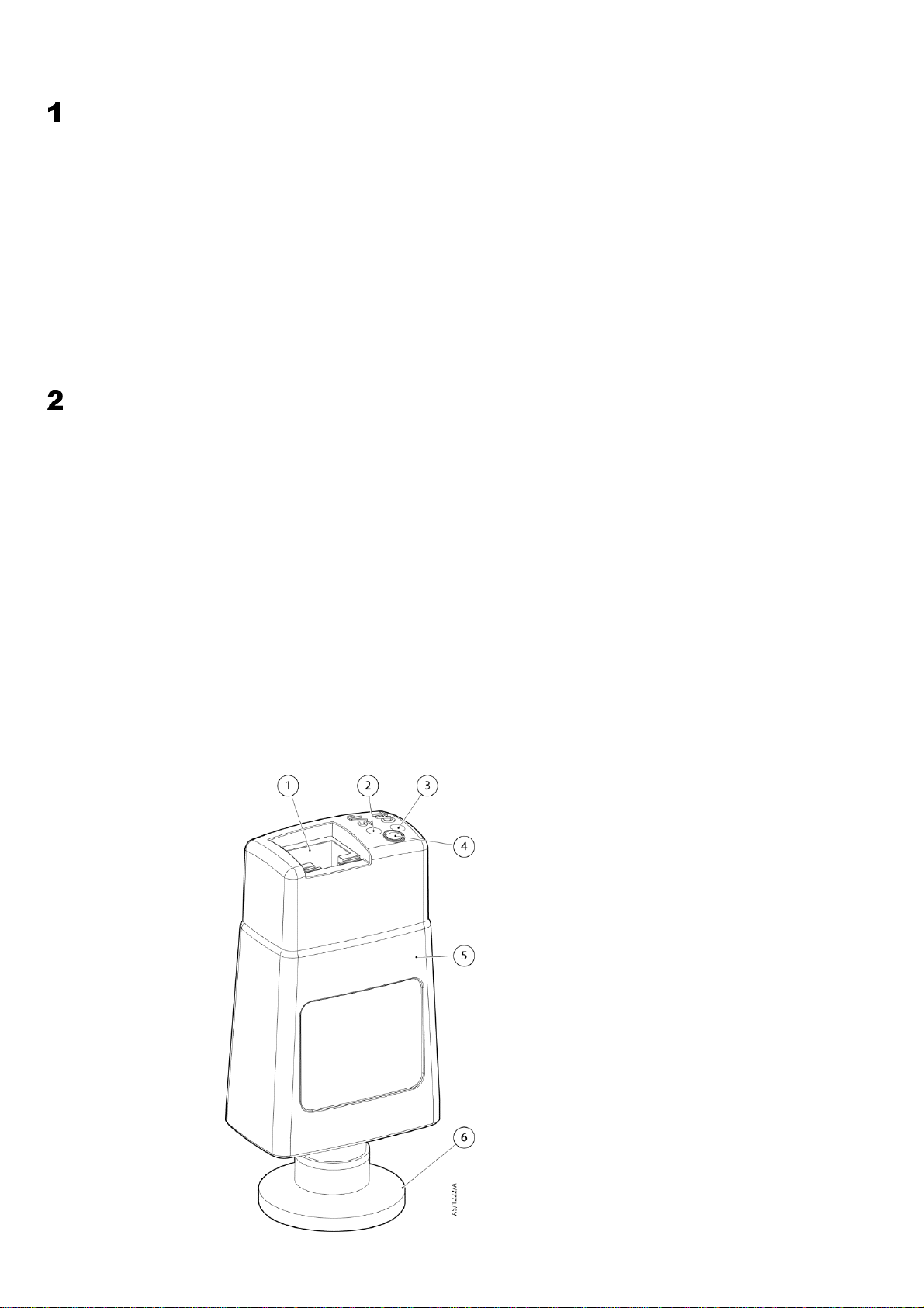
A general view of the gauge is shown below. The gauge features a detachable tube which allows a replacement to
be fitted in the event of contamination or failure of the filament. There are two push-button switches on the top of the
gauge. The switch labelled "CAL" is used for atmosphere and vacuum calibration and the switch labelled "S/P" is
used to adjust the set-point threshold.
The transmitters have one programmable set-point (transistor output) which can be used for process control, for
example interlocking valves or pumps. The analogue voltage output can be interfaced to external analogue
equipment for pressure readout or controlling.
General view of the TTR 91 R
1
Electrical connector
2
Set-point button
3
CAL button
4
Status LED
5
Electronics housing
6
Vacuum flange

6300710168_002_C1 - 01/2018 - © Leybold
Technical data
Mechanical data
Dimensions
Refer to the next page
Mass
85 g
Internal volume of tube
5 cm3
Enclosure rating
IP40
Performance, operating and storage conditions
Displayed pressure range
5×10⁻⁴ to 1000 mbar
Accuracy
typically ± 15 % at < 100 mbar
Ambient temperature
Operation
5 to 60 °C
Storage
-30 to +70 °C
Bakeout
150 °C (with electronics housing removed)
Humidity
80 % RH up to 31 °C decreasing linearly to 50 % RH
at 40 °C and above
Maximum altitude
3000 m (indoor use only)
Maximum internal pressure
10 bar absolute (9 bar gauge)
Filament temperature
100 °C above ambient
Materials exposed to vacuum
Filament
Tungsten / Rhenium
Tube
Stainless Steel 316L & 304L
Filter
Stainless Steel
Other
Glass, Ni, NiFe, Stainless Steel
Electrical data
Supply voltage
nominal
15 to 30 V d.c.
minimum
13.5 V
maximum
32 V
Maximum power consumption
1 W
Max inrush current
150 mA
Electrical connector
FCC68 / RJ45 8-way
Pressure output
Sensor output
1.9 to 10.0 V
Sensor fail
0.5 V
Min load impedance
10 kΩ
Max output current
1 mA
Set-point
Adjustment range
1.4 to 10.0 V
Hysteresis
500 mV
Max external load rating
30 V d.c., 100 mA
Gauge identification resistance
27 kΩ

7300710168_002_C1 - 01/2018 - © Leybold
Dimensions (mm)

8300710168_002_C1 - 01/2018 - © Leybold
Accessories and replacement part numbers
Part
Part no.
TTR 91 R DN16 KF
230049V01
Replacement tube
TTR 91 R DN16 KF
E02601801
Operating Units
Display One
230001
Display Two
230024
Display Three
230025
Graphix One
230680V01
Graphix Two
230681V01
Graphix Three
230682V01
Cables
Cables Type A 5 Meter
12426
Cables Type A 10 Meter
230012
Cables Type A 15 Meter
12427
Cables Type A 20 Meter
12428
Cables Type A 30 Meter
12429
Cables Type A 50 Meter
12431
Cables Type A 75 Meter
12432
Cables Type A 100 Meter
12433
Accessories
Centering Rings (Stainless Steel 1.4305) with O-Ring, DN16
KF
88346
Centering Rings (Stainless Steel) with Sintered Metal Filter,
DN16 KF
88351
Clamping Rings (Aluminum), DN16 KF
18341
Centering Ring with fine filter DN 16 ISO-KF
88396
Calibration service
A calibration service is available for all Leybold gauges. Calibration is by comparison with reference gauges,
traceable to National Standards. Contact Leybold for details.

9300710168_002_C1 - 01/2018 - © Leybold
Installation (mechanical)
The TTR 91 R can be mounted in any orientation however the gauge tubes are individually factory calibrated whilst
vertical. For correct pressure indication in your chosen gauge orientation, the gauge should be recalibrated at
atmospheric pressure. Leybold recommends mounting the gauge tube vertical in order to minimise the build up of
process particulates and condensable vapours within the gauge.
For optimum accuracy it is recommended that both the atmosphere and vacuum adjustment is carried out before
use. Refer to the Maintenance section.
To connect the TTR91R to your vacuum system use an 'O' ring / centring-ring to connect a TTR91R with a DN16
ISO-KF flange to a similar flange on the vacuum system.
To connect to a Leybold controller use a shielded cable which is terminated in suitable RJ45 connectors. These
cables are available from Leybold (Cable Type A).
The TTR91R is compatible with the GRAPHIX and DISPLAY controllers from Leybold. The controllers will
automatically recognize the gauge and display the measured pressure.
Installation (Electrical)
Do not make any connection to the gauge identification pin (pin 4) as this may cause the gauge to malfunction.
A schematic diagram of the recommended electrical connections to the TTR 91 R is shown below. The pins on the
electrical connector are used as shown in the below table. Refer to the Technical Data section for more detailed
specifications.
Pins on the TTR 91 R electrical connector
Pin number
Use
1
Electrical supply positive
2
Electrical supply ground (0 V)
3
Pressure measurement output signal
4
Gauge identification
5
Signal ground
6
Set-point output signal
7
Remote calibration input
8
Not connected
Do not use the TTR 91 R for safety critical applications. The TTR 91 R is not intended to be fail-
safe
!
Caution
!
Attention
!

10 300710168_002_C1 - 01/2018 - © Leybold
Recommended electrical connections
Do not connect the electrical supply ground (pin 2) to the signal ground (pin 5). If you do, the TTR 91 R output signal
will be inaccurate.
When using the TTR 91 R in an electrically noisy environment you should ensure that your measuring equipment is
adequately immune to interference. All Leybold controllers have adequate immunity.
The set-point output on pin 6 is an active low open-collector transistor suitable for driving a d.c. relay or control logic.
If you connect a relay you must use a suppression diode, to protect the gauge from transient voltages generated
when the relay is switched off.
Make a connection to pin 7 if you require remote calibration. Momentarily (>50ms) connect pin 7 to pin 2 (ground) to
automatically adjust the atmosphere or vacuum reading. Refer to the Maintenance section for the correct procedure
1
TTR 91 R electrical connector
socket
2
Cable electrical connector plug
3
Electrical supply
4
Voltmeter
5
d.c. relay (optional)
6
Back EMF suppression diode
(optional)
7
Remote calibration switch
(optional)

11 300710168_002_C1 - 01/2018 - © Leybold
Operation
Pressure measurement
When the TTR 91 R is connected to a power supply the status LED will turn amber for approximately 2 seconds.
The status LED will then turn green if the gauge is operating correctly or red if an error is detected. Refer to the fault
finding guide.
If the gauge is connected to a Leybold controller the display will indicate the measured pressure.
The TTR 91 R provides a voltage output which is a function of pressure. The output voltage scales with 1.296V dc /
decade.
Conversion formulae:

12 300710168_002_C1 - 01/2018 - © Leybold
Voltage pressure conversion for TTR 91 R
P (mbar)
Voltage (V)
P (mbar)
Voltage (V)
P (mbar)
Voltage (V)
5.00E-04
1.898
7.00E-02
4.658
9.00E+00
7.370
6.00E-04
2.000
8.00E-02
4.732
1.00E+01
7.429
7.00E-04
2.086
9.00E-02
4.798
1.50E+01
7.655
8.00E-04
2.160
1.00E-01
4.857
2.00E+01
7.816
9.00E-04
2.226
1.50E-01
5.083
3.00E+01
8.043
1.00E-03
2.285
2.00E-01
5.244
4.00E+01
8.203
1.50E-03
2.511
3.00E-01
5.471
5.00E+01
8.328
2.00E-03
2.672
4.00E-01
5.631
6.00E+01
8.430
3.00E-03
2.899
5.00E-01
5.756
7.00E+01
8.516
4.00E-03
3.059
6.00E-01
5.858
8.00E+01
8.590
5.00E-03
3.184
7.00E-01
5.944
9.00E+01
8.656
6.00E-03
3.286
8.00E-01
6.018
1.00E+02
8.715
7.00E-03
3.372
9.00E-01
6.084
1.50E+02
8.941
8.00E-03
3.446
1.00E+00
6.143
2.00E+02
9.102
9.00E-03
3.512
1.50E+00
6.369
3.00E+02
9.329
1.00E-02
3.571
2.00E+00
6.530
4.00E+02
9.489
1.50E-02
3.797
3.00E+00
6.757
5.00E+02
9.614
2.00E-02
3.958
4.00E+00
6.917
6.00E+02
9.716
3.00E-02
4.185
5.00E+00
7.042
7.00E+02
9.802
4.00E-02
4.345
6.00E+00
7.144
8.00E+02
9.876
5.00E-02
4.470
7.00E+00
7.230
9.00E+02
9.942
6.00E-02
4.572
8.00E+00
7.304
1.00E+03
10.000

13 300710168_002_C1 - 01/2018 - © Leybold
Gas dependency
The TTR 91 R is calibrated for use in nitrogen, and will read correctly with dry air, oxygen and carbon monoxide. For
any other gas type a conversion is required in order to obtain the correct pressure reading. The graph below shows
the conversion for 6 common gases: nitrogen, argon, carbon dioxide, helium, krypton and neon.
Gas dependency of TTR 91 R
For pressures below 1 mbar a simple calibration factor can be used to correct for different gas types. Gas Calibration
Factors (GCFs) for common gases are shown below.
True pressure = GCF x indicated pressure
Gas calibration factors below 1 mbar
Gas
GCF
He
1.1
Ne
1.5
N2
1.0
Ar
1.7
CO2
1.0
Kr
2.6
He
Ne
N2
CO2
CO2
Ar
Kr

14 300710168_002_C1 - 01/2018 - © Leybold
Set-point adjustment
When the ‘S/P’ button is pushed the gauge output will change. Do not push the ‘S/P’ button to adjust the set- point if
the change in output could cause a malfunction of your system.
Note: If you use a Leybold Controller the TTR 91 R set-point is not used.
To read the pressure at which the set-point output turns on, push the "S/P" button with an appropriate tool. The signal
output of the gauge will change to indicate the set-point threshold for three seconds after which the output will return
to normal.
The set-point has a fixed hysteresis of 500 mV. When the measured pressure falls below the set-point pressure the
transistor output changes to ON (closed). The transistor output will turn OFF when the measured pressure rises to
500 mV above the set-point pressure. An external relay connected as shown in section 4 will turn on when the
pressure falls below the set-point and turn of when the pressure rises to 500 mV above the set-point.
To adjust the set-point threshold push the "S/P" button and hold it down for more than three seconds. The threshold
value will increase steadily. Release the button when you reach the required value. To make finer adjustment release
the button just before the required value is reached and immediately push the button as many times as required.
Each time you push the button the threshold value will increase by 10 mV. If during adjustment the threshold reaches
the maximum value (10.0 V) it will jump to the minimum (1.4 V) and increase again.
If you do not need to use the set-point or if you require the set-point to be permanently off, you can adjust the
threshold to 1.4 V. This will ensure that the set-point does not operate. The TTR 91 R is shipped from the factory
with the threshold set to 1.4 V.
The set-point can also be used to indicate that the gauge is operating correctly. If you adjust the threshold to 10.0 V
then the set-point output will be ON as long as the gauge is operating correctly and will turn OFFif an error is detected
Adjusting the set-point
.
Attention
!

15 300710168_002_C1 - 01/2018 - © Leybold
Error monitoring
If an error occurs during operation of the TTR 91 R then the status LED will turn red to indicate an error and the
output voltage will change to indicate an error condition. Error voltages are shown in the table below. The set-point
will be disabled as soon as an error is detected. Refer to the FAQ section.
Error indication
Error condition
Output (V)
Broken filament or tube removed
0.5
Calibration error
0.5
Bakeout
In some UHV applications it is desirable to bake the vacuum system components in order to achieve a lower base
pressure. The tube of the TTR 91 R can be baked to 150°C, but the electronics housing must be removed.
Referring to the figure in section 6.7, remove the electronics housing. When baking the tube on your system, do not
exceed 150°C. Always allow the tube to cool before refitting the electronics housing.

16 300710168_002_C1 - 01/2018 - © Leybold
Maintenance
Atmosphere and vacuum adjustment
Every TTR 91 R is individually adjusted before shipment, however thermal conductivity gauges can drift with time or
as contamination builds up on the filament. Use the procedures outlined below to adjust the atmosphere and vacuum
settings of the gauge. The frequency with which they should be repeated will vary depending on the level and nature
of the contamination associated with the process.
Adjustment of TTR 91 R
Atmosphere adjustment
1. Switch on the power supply to the TTR 91 R and allow it to operate at atmospheric pressure for at least 10
minutes. Ensure that the green status LED is lit.
2. Press the 'CAL' button. The status LED turn amber and the gauge will automatically adjust to read
atmospheric pressure. Do not hold the ‘CAL’ button down for longer than 5 seconds (see ‘Adjustment for
new tube’ below).

17 300710168_002_C1 - 01/2018 - © Leybold
Vacuum adjustment
1. Reduce the system pressure to 1 x 10⁻⁴ mbar (or below).
2. Allow the gauge to operate for at least 10 minutes.
3. Momentarily press the 'CAL' button. Do not hold the ‘CAL’ button down for longer than 5 seconds (this would
start the ‘Adjustment for new tube’, as described below). The status LED will turn amber and the gauge will
automatically adjust to read vacuum.
Remote adjustment
The atmosphere and vacuum adjustments can be performed remotely using a switch connected as shown in the
Figure in section 4.1. Follow the procedure described above, but momentarily close the remote switch instead of
using the ‘CAL’ button on the gauge.
Adjustment for new tube
If a replacement tube is fitted to the gauge it will be necessary to adjust the gauge to match the new tube. Note that
this is not required unless a new tube is fitted, and it is always necessary to perform a vacuum adjustment afterwards.
1. Switch on the power supply to the TTR 91 R.
2. With the gauge at atmospheric pressure, press the 'CAL' button and hold it down for longer than 5 seconds.
The status LED will begin to flash red / green alternately and the gauge will automatically adjust to match
the new tube. This may take several seconds.
3. Allow the gauge to operate at atmospheric pressure for at least 10 minutes and then repeat step 2.
4. It is now necessary to perform the vacuum adjustment as described above.
.

18 300710168_002_C1 - 01/2018 - © Leybold
Replace the gauge tube
If the gauge tube has become severely contaminated so that atmosphere or vacuum adjustment cannot be achieved,
or if the filament is broken, then you can fit a replacement tube to the gauge.
Refer to the below figure and follow this procedure to replace the gauge tube.
Unplug the electrical cable, vent the vacuum system to atmospheric pressure and remove the gauge from the
vacuum system.
Pull the retaining clip from side of gauge.
Pull the tube from the electronics housing.
Fit the replacement tube into electronics housing, noting the correct alignment.
Refit the retaining clip.
Whenever a new tube is fitted it is necessary to adjust the gauge to match the new tube. Refer to ‘Adjustment for
new tube’ above. Replacement of gauge tube
1
Electronic housing
2
Retaining clip
3
Gauge tube

19 300710168_002_C1 - 01/2018 - © Leybold
FAQ (Frequently Asked Questions)
Fault finding Guide
Symptom
Possible cause
Remedy
LED not lit
Incorrect electrical
supply voltage.
Supply polarity
reversed.
Check electrical
supply and
connections
Pressure reading incorrect
Vacuum leak
Leak check vacuum
system
Tube has drifted
and requires
adjustment
Perform the
atmosphere and
vacuum adjustments
Tube contaminated
Replace the tube
Gauge indicates error voltage
Adjustment has
been attempted at
an inappropriate
pressure
Repeat the
adjustment but make
sure that the pressure
is at atmosphere or
good vacuum
New tube has been
fitted
Perform ‘Adjustment
for new tube’
Tube has drifted
outside permissible
limits and can no
longer be adjusted
Replace the tube
Tube is missing
Fit the tube and
remove then re- insert
the electrical
connector
Filament is broken
Replace the tube
Storage and disposal
Dispose of the TTR 91 R and any components safely in accordance with all local and national safety and
environmental requirements.
Particular care must be taken if the TTR 91 R has been contaminated with dangerous process substances
For the benefit of the environment, at the end of life of the transmitter, it should not be disposed in
the normal unsorted waste stream. It should be deposited at an appropriate collection point or facility
to enable recovery or recycling.
Attention
!

20 300710168_002_C1 - 01/2018 - © Leybold
Declaration of Contamination
Safety information on contamination of compressors, vacuum pumps and components.
Scope:
Every employer (user) is held responsible for the health and safety of his employees. This also applies to
service personnel performing maintenance work either at the premises of the user or the service company in
charge.
By means of the declaration attached the contractor is to be informed about any possible contamination of the
compressor, vacuum pump or component sent in for servicing. Based on this information the contractor will be
able to take the necessary safety precautions.
Preparation before dispatch
Before shipping any parts, the user must complete the following declaration and add it to the dispatch papers.
All dispatch instructions laid down in the manual must be followed e.g.:
•Drain all service fluids
•Remove filter elements
•Seal all openings airtight
•Pack / handle appropriately
•Attach the declaration of contamination outside of the packaging
Table of contents
Other LEYBOLD Transmitter manuals

LEYBOLD
LEYBOLD PENNINGVAC PTR 90 N User manual

LEYBOLD
LEYBOLD THERMOVAC TTR 211 S User manual

LEYBOLD
LEYBOLD CERAVAC CTR 100 N User manual

LEYBOLD
LEYBOLD THERMOVAC TTR 91 N User manual

LEYBOLD
LEYBOLD PENNINGVAC PTR 90 N How to use

LEYBOLD
LEYBOLD THERMOVAC TTR 101 N User manual

LEYBOLD
LEYBOLD IONIVAC Series User manual
Popular Transmitter manuals by other brands

Decade
Decade TRC-800 instruction manual

ZIEHL-ABEGG
ZIEHL-ABEGG ZAmon STICK manual

SkyLink
SkyLink HW-434 User instructions

Altinex
Altinex Computer/Component Video+ Audio Dual Twisted Pair Transmitter... user guide

M-system
M-system 35mm instruction manual

R.V.R. Elettronica
R.V.R. Elettronica TEX302TFT user manual