8 | PRODUCT DATA
Art Cool™Mirror Wall Mounted Engineering Manual
'XHWRRXUSROLF\RIFRQWLQXRXVSURGXFWLQQRYDWLRQVRPHVSHFL¿FDWLRQVPD\FKDQJHZLWKRXWQRWL¿FDWLRQ
© /*(OHFWURQLFV86$,QF(QJOHZRRG&OLIIV1-$OOULJKWVUHVHUYHG³/*´LVDUHJLVWHUHGWUDGHPDUNRI/*&RUS
PRODUCT FEATURES AND BENEFITS
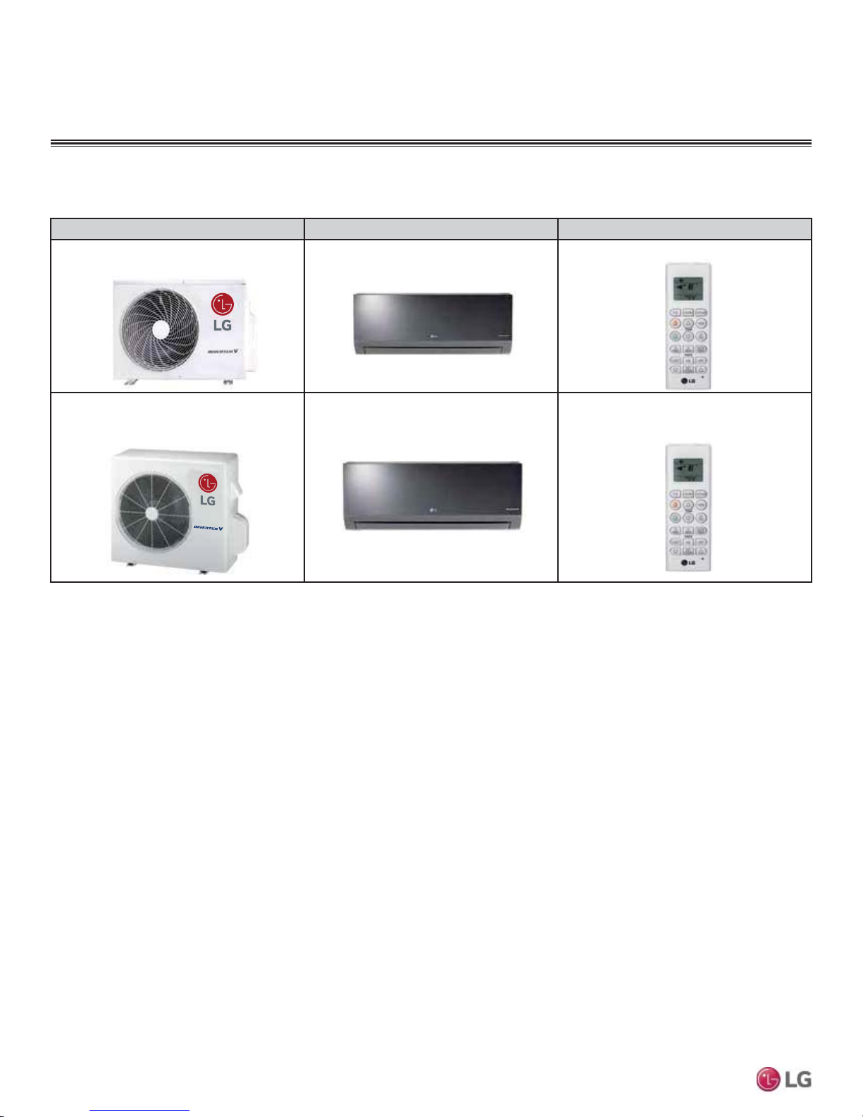
Single Zone Art Cool™
Mirror Wall Mount
Single zone systems are equipped with
inverter components that offer superior
load matching and long piping installation.
The product works for optimizing power
consumption in residential and small office
buildings. Utilizing multiple indoor wall mount
units each with custom temperature controls
allow for precise temperature settings in
each zone of the building. Single zone sys-
tems allow flexibility in interior design and
complement any decor.
Low Sound Levels
When outdoor units run at full load, they
have a quiet operating sound level. To pro-
mote a quiet, comfortable environment, the
LG single zone system indoor units operate
at sound levels as low as 23 dB(A) (19dB(A)
in sleep mode) and the outdoor units as low
as 45 dB(A) at full load.All rotating compo-
nents are soft-started by the controller using
digitally controlled inverters, which reduce
undesirable noise caused by fans and com-
pressors cycling on and off.
Comfort Control at Its
Best
Unlike traditional air conditioning control
systems, which use thermostatic controls to
maintain room temperatures, LG single zone
inverter controls continuously vary the indoor
unit fan speed and refrigerant flow.
LG single zone one-to-one systems continu-
ously measure the room temperatures and
adjust system operations accordingly to
maintain set temperature.
The outdoor unit responds by varying the
compressor speed and outdoor fan mo-
tors as needed to maintain system operat-
ing pressure.As a result, the single zone
systems deliver targeted space temperature
control.
Inverter Driven
The rotary (9k/12k Btu/h systems) and
twin-rotary (18k/24k Btu/h systems) com-
pressors are optimized to maximize com-
pressor efficiency, which reduces power
consumption and monthly utility bills. This
latest inverter technology allows single zone
system outdoor units to vary the compressor
motor shaft speed to deliver an appropriate
amount of cooling to the indoor unit. Precise
refrigerant volume delivery translates into
long periods with coil surface temperatures
below dew point and minimizes compressor
and fan component run time which may lead
to lower utility usage.
Simplified Installation
Cooling and heating applications that use
single zone systems simplify and reduce the
mechanical and control system design time.
The designer no longer has to be concerned
with interconnecting chilled and condenser
water piping, air-distribution duct systems,
matching and selecting chillers, towers,
pumps, coils, fans, air handlers, or Variable
Air Volume (VAV) boxes.
Operating Range
Single zone systems have a nominal capac-
ity range of 3/4 to 2 tons (depending on
outdoor/indoor units).
Outdoor unit operating ranges for single
zone systems:
Cooling: 14°F DB to 118°F DB
Heating: -4°F WB to 65°F WB
Installing an optional LowAmbient Wind
Baffle Kit will allow operation down to 0°F in
cooling mode for these single zone systems.
Compact Size
Single zone outdoor units have the following
footprints.
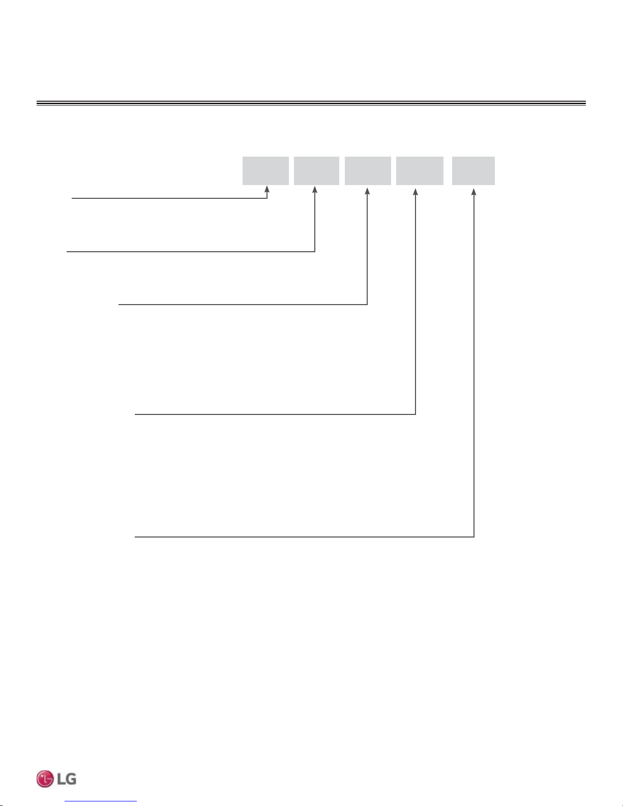
LSU090HSV4, LSU120HSV4
(WxHxD (in)) 30 5/16 x 21-1/2 x 11-5/16.
LSU180HSV4, LAU240HSV3
(WxHxD (in)) 34-1/4 x 31-1/2 x 12-5/8.
Fin Design with Gold-
Fin™ Coating
All single zone outdoor units are provided
with large surface coils made of copper
tubes with louvered aluminum fins designed
to maximize unit operating efficiency over a
wide range of ambient conditions.
Standard from the factory, every single
zone outdoor unit coil fin surface is
coated with LG’s exclusive GoldFin™
anti-corrosive coating designed to prevent
natural surface corrosion of the alumi-
num fins. This maintains heat transfer
properties of the coil for an extended time.
Ahydrophilic coating is applied to the
outdoor unit coil fin surface over the GoldFin
coating. This coating enhances the develop-
ment of heavier water droplets gathering on
the fin surface. As a result, the droplets roll
off the fin surfaces, delaying the point when
frost forms on the coil surface during heat-
ing operation. This coating also makes it
possible to easily clean the outdoor unit coil
using a mild soap.
Other Features
• Inverter variable speed compressor
• Jet Cool / Jet Heat
• Dehumidifying mode
• 3M™Micro Protection Filter
• Chaos Wind
• Auto restart
• Auto operation
• Self-cleaning indoor coil
• Condensate sensor connection
• Precision load matching
• MeetsAHRI 210/240


 User manual")


 null")