LG DELUXE HIGH WALL MINI SPLIT User manual

DELUXE HIGH WALL MINI SPLIT
INSTALLATION INSTRUCTIONS
IMPORTANT!
Please read this instruction sheet completely before installing the product.
This air conditioning system meets strict safety and operating standards. As the installer or service person, it is
an important part of your job to install or service the system so it operates safely and efficiently.
f•Installationor repairsmade by unqualified personscan result in hazards toyou andothers.
InstallationMUSTconform with localbuilding codesor, in the absenceof local codes,with the National Electrical
Code NFPA7O/ANStC1-t 993or current edition andCanadian Electlical Code Part1 CSA C.22 I.
•The information containedin the manual is intended for use bya qualifiedservice technicianfamiliarwith safety
proceduresandequipped with the proper tools and test instruments.
• Failureto carefullyreadandfollow all instructionsin thismanual can resultin equipment malfunction,property
k,. damage,personal injuryand/ordeath.
CAUTION: Improper instaIlaflon, adjustment, aIteration, service or maintenance can void the warranty
The weight of the condensing unit requires caution and proper handling procedures when
lifting or moving to avoid personal injury. Use care to avoid contact with sharp or pointed
edges
Safety Precautions
• Always wear safety eye wear and work gtoves when rhstalling equipment
• Never assume etectricaI power is disconnected. Check with meter and equipment
• Keep hands out of fan areas when power is connected to equipment.
• R-22 causes frostbite burns
• R-22 is toxic when burned
NOTE TO INSTALLING DEALER: The Owners instructions and Warranty are to be given to the owner or
prominently displayed near the indoor Furnace/Air Handler Unit.
fWhen wiring: "_
Electrical shock can cause severe personal injury or death. Only a qualified, experienced electrician
should attempt to wire this system.
•Do notsupply power to the unit until allwiring and tubing are completedor reconnectedand checked.
•Highlydangerouselectricalvoltagesare usedin thissystem Carefullyrefertothewiringdiagramandtheseinstructions
whenwiring,improperconnectionsandinadequategroundingcan causeaccidentalinjuryordeath
• Ground the unit following local electrical codes.
•Connectallwiringtightly.Loosewiril_jmay causeoverheatingatconnectionpointsanda possiblefire hazard
When transporting:
Be careful when picking up and moving the indoor and outdoor units. Get a partner to help, and bend your
knees when lifting to reduce strain on your back. Sharp edges or thin aluminum tins on the air conditioner
can cut your finger.
When installing...
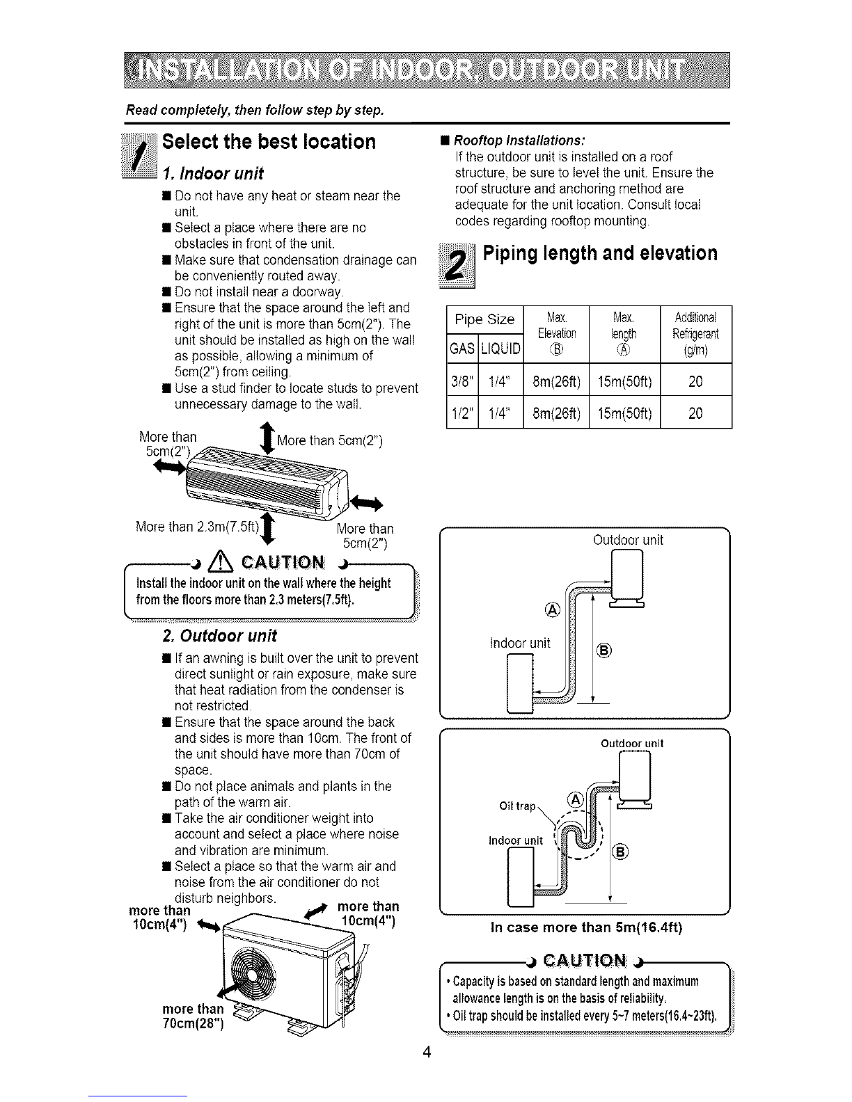
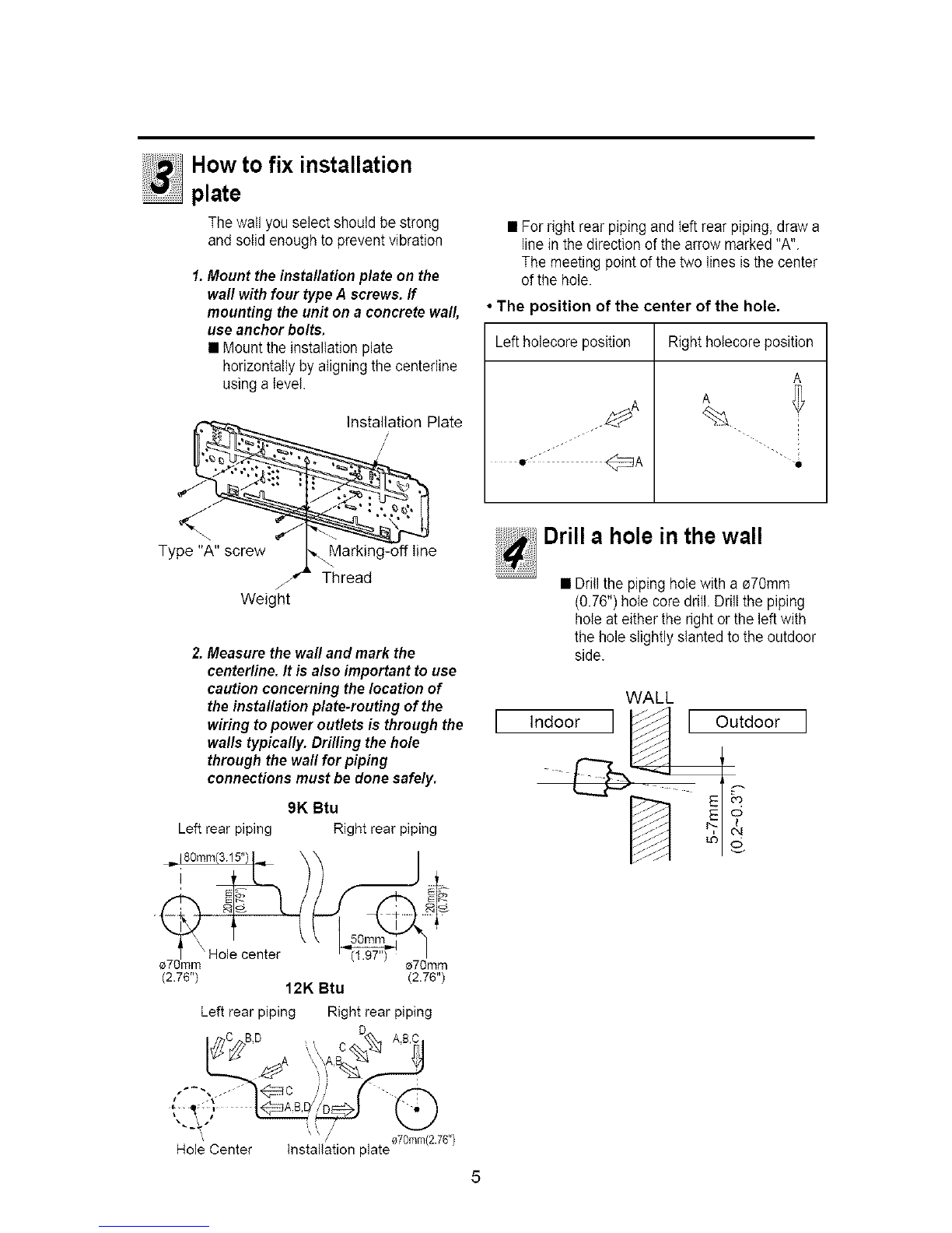
... in awall: Make sure the wall is strong enough to holdthe unit's weight.
It may be necessary to construct a strong wood or metal frame to provide added support.
... in a room: Properly insulate any tubing run inside a roomto prevent "sweating" that can cause dripping
and water damage to wall and floors.
... in moist or uneven Iocatinons: Use a raised concrete pad or concrete blocks provide a solid, level
foundation for the outdoor unit. This prevents water damage and abnormal vibration.
... in an area with high winds: Securely anchor the outdoor unit down with bolts and a metal frame.
Provide a suitable air baffle.
... in a snowy area(for Heat Pump Model): Install the outdoor unit on a raised platform that is higher than
drifting snow. Provide snow vents.
When connecting refrigerant tubing
• Keep all tubing runs as short as possible.
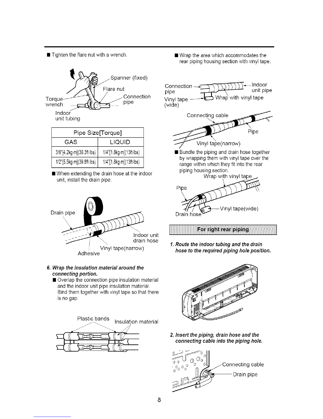
• Use the flare method for connecting tubing.
• Check carefully for leaks before starting the test run.
When servicing
•Turn the power OFF at the main power box(mains) before opening the unit to check or repair electrical
parts and wiring.
• Keep your fingers and clothing away fl-omany moving parts.
• Clean up the site after you finish, remembering to check that no metal scraps or bits of wiring have been
k. left inside the unit being serviced. _'
P/No:3828A20094D

The following should be
always observed for safety .3
Installation of indoor, outdoor
unit............................................4
Flaring work and connection
of piping ...................................6
Connectionof piping(Indoor)..7
For rightrear piping
For left rear piping
Connection of
piping(Outdoor) ..................10
Connecting the cable
between indoor unitand
outdoor unit..........................11
Checking the drainage and
Formingthe piping ................14
Air Purging .............................15
Test running..........................17
13Level gauge
[:ZIScrew driver
[:ZIElectric drill
13Hole core drill_70mm(2.79")
[:ZIPipes: Gas side........1/2",3/8"
Liquid side .............1/4"
(Refer to page4)
[:ZIInsulation materials
13Additional drain pipe
OuterDiameter-..-.-15.5mm(5/8")
[:ZITwo type "B"screws
13Installation plate
13Four type "A" screws
13Connecting cable
13Flaring tool set
13Specified torque wrenches
1.8kg.m(13ftIbs),42kgm(30.3ftbs),
5.5kg.m(39.8ft.bs),
6.6kg.m(47.7ft.bs)
(differentdependingonmodelNo)
(Refer to page 10)
13Spanner ..................Half union
13A glass ofwater
[:ZIScrew driver
13Hexagonal
Wrench(4mm:5/32")
[:3Owner's manual
CIThermometer
Installation Parts Provided I
1. Type "A" screw
2. Installation Plate
3. Type "B" screw
4. Holder Remote Control

•Besuretoread"THEFOLLOWINGSHOULDALWAYSBEOBSERVEDFORSAFETY"beforeinstalling
theairconditioner.
•Besuretoobservethecautionsspecifiedhereastheyincludeimportantitemsrelatedtosafety.
•Theindicationsandmeaningsareasfollows.
,/_ WARNING J
Could lead to death, serious injury, etc.
,J ,/_ CAUTION
Could lead to serious injury in particular environments when operated incorrectly.
• After reading this manual, be sure to keep ittogether with the instruction manual in a handy place on the
customer's site.
• Incomplete installation could cause injury dueto
fire, electric shock_the unit failing or a leakage
of water. Consult the dealer from whom you
purchased the unit or special installer.
• When installedin an insufficient strong place_
the unit could fall causing injured.
•Incomplete connecting and fixing could cause
fire.
• Incomplete installation could cause apersonal
injury due to fire, electric shock_the unit failing or
a leakage of water.
• Ifthe capacity ofthe power circuit is insufficient
or there is incomplete electrical work, it could
result in afire or an electric shock.
• If the electrical part cover if the indoor unit and/or .Theuseofdefectivepartscouldcauseaninjuryorleakage
the service panel if the outdoor unit are not ofwaterduetoafire,electricshock,theunitfailing,etc
attached securely, it could result in a fire or
electric shock due to dust, water, etc.
,._//_ CAUTION J

Read completely, then follow step by step.
Select the best location
1.Indoor unit
• Do not have any heat or steam near the
unit.
• Select a place where there are no
obstacles in front of the unit.
• Make sure that condensation drainage can
be conveniently routed away.
• Do not install near a doorway.
• Ensure that the space around the teft and
rightof the unit is more than 5cm(2"). The
unit should be installed as high on the wail
as possible, allowing a minimum of
5cm(2") from ceiling.
• Use a stud finder to locate studs to prevent
unnecessary damage to the wail.
More than 'More than 5cm(2")
5cm,
•Rooftop/nsta//ations:
If the outdoor unit is installed on a roof
structure, be sure to level the unit. Ensure the
roof structure andanchoring method are
adequate for the unit location. Consult local
codes regarding rooftop mounting.
Piping length and elevation
Pipe Size Max Max Additional
Bevation length Refrigerant
GAS LIQUID _D @ (g/m)
3/8" 1/4" 8m(26ft) 15m(50ft) 20
1/2" 1/4" 8m(26ft) 15m(50ft) 20
More than 2.3m(7.5ft)' Morethan
5em(2")
_io _ ,/_ CAUTION:
ndoorunit onthewallwheretheheight
orsmorethan2.3meters(7.5ft), |
2. Outdoor unit
• Ifan awning is built over the unit to prevent
direct sunlight or rain exposure, make sure
that heat radiation from the condenser is
not restricted.
• Ensure that the space around the back
and sides is more than 10cm. The front of
the unit should have more than 70cm of
space.
• Do not place animals and plants in the
pathof the warm air.
• Take the air conditioner weight into
account and select a place where noise
andvibration are minimum.
• Select a place so that the warm air and
noise from the air conditioner do not
disturb neighbors.
more than more than
10cm(4") _10cm(4")
more than
70cm(28")
Outdoor unit
Ind®_ur___
Outdoor unit
In case more than 5m(16,4ft)
__ CAUTION J_ 1
,Capacityisbasedonstandardlengthandmaximum /
.allowancelengthis onthebasisofreliability, /
•Oi!trapshouldbeinstalledevery5~7meters(16,4~23ft),

How to fix installation
plate
The wail you select should be strong
and solid enough to prevent vibration
1.Mount the installation plate on the
waft with four type A screws, ff
mounting the unit on a concrete waft,
use anchor bolts.
• Mount the installationplate
horizontally by aligning the centerline
using a level•
Plate
Type "A" screw I,,_ Marking-off Iine
_,.,_,t, "-Thread
f
Weight
2,Measure the wall and mark the
center/ine, /t is also important to use
caution concerning the location of
the installation plate-routing of the
wiring to power outlets is through the
walls typically. Drilling the hole
through the waft for piping
connections must be donesafely.
9K Btu
Left rear piping Right rear piping
= 180ram(3 15")I= \\ /
' Hole center (1._r') __
e7Omm _70mm
(2.76") (2.76")
12K Btu
Left rear piping Right rear piping
• Forright rear piping and left rear piping, draw a
line in the direction of the arrow marked "A".
The meeting point of the two lines is the center
of the hole.
•The position of the center of the hole.
Leftholecore position Right holecore position
A
A
%m_• i
•ll
Drill ahole in the wall
• Drillthe piping hotewith a _70mm
(0.76") hole core drill. Drill the piping
hole at either the right or the left with
the hole slightly slanted to the outdoor
side.
WALL
IIndoor I[Outdoor I
L:)
"--_" ii /
_, \ _ /oT0mrn(2 76")
Hole Center installation plate

Flaring work
Main causefor gas leakageisdue to
defect inflaring work. Carry out correct
flaring work in the following procedure.
1. Cutthe pipes and the cable.
•Use the piping kit accessory or the
pipes purchased locally.
• Measure the distance between the
indoorand the outdoor unit.
• Cut the pipes a little longer than
measured distance.
• Cut the cable 1.5m(4.9ft) longer than
the pipe length.
Copper 0 X
pipe ,_P'_,_ 90_,
2. Burrs removal
• Completely remove all burrs from the
cut cross section of pipe/tube.
• Put the end of the copper tube/pipe in
a downward direction as you remove
burrs in order to avoid dropping burrs
into the tubing.
Reamer
Point down
3. Putting nut on
• Remove flare nuts attached to indoor
and outdoor unit, then put them on
pipe/tube having completed burr
removal.
(not possible to put them on after
flaring work)
4. Flaring work
• Carry out flaring work using flaring toot as
shown below.
Outside diameter A
mm inch mm
e6.35 1/4 0~0.5
e9.52 3/8 0~0.5
e12.7 1/2 0~0.5
_15.88 5/8 0~1.0
Firmly hold copper pipe in adie in the
dimension shown in the table above.
_:/ __ j_ - Handle
Bar = _ Ba_
_-_ Yoke
L_ _"_ I/._ e
Cepperpipe
Clamp handle _ Red arrow mark
5. Check
• Compare the flared work with figure below.
• Ifflare is noted to be defective, cut off the
flared section and do flaring work again.
Smooth all round
is shiny without scratches
Improperflaring :
all round
Flare nut
Copper_

Connection of piping --
Indoor
• Preparing the indoor unit's piping and
drain hose for installation through the
wall.
• Remove the plastic tubing retainer(see
illustration below) and pull the tubing
and drain hose away from chassis.
• Replace the plastic tubing holder in
To removethe---_o[der_ --"_"-' ,
press the bottom of _..,--d L--- i
chassis near the holder _ud_2>Pull I
upward and pull the tab (1_ I
out of its hole. __v' I
CAUTION
When install make sure that
the remaining parts must be
removed clearly so as notto
damage the piping and drain
hose, especially connecting
cab e.
3. Tape the tubing, drain hose and the
connecting cable. Be sure that the drain
hose is located at the lowest side of the
bundle. Locating at the upper side can
cause drain pan to overflow inside the unit.
NOTE: if the drain hose is routed inside the
room, insulate the hose with an insulation
material* so that dripping from
"sweating"(condensation) will not damage
furniture or floors.
*Foamed polyethylene or equivalent is
recommended.
4. Indoor unit installation
• Hook the indoor unit onto the upper portion
of the installation plate.(Engage the two
hooksof the rear top of the indoor unit with
the upper edge of the installation plate.)
Ensure that the hooks are properly seated
on the installation plate by moving it left and
right.
1.Route the indoor tubing and the drain
hose in the direction of rear/eft.
Drainhose
2./nsert the connecting cable into the
indoor unit from the outdoor unit
through the piping hole.
• Do not connect the cable to the indoor
unit.
• Make a small loop with the cable for
easy connection later.
Connecting
cable
hose
Press the lower left and right sides of the unit
against the installation plate until the hooks
engage into their slots(clicking sound).
5. Connecting the pipings to the indoor unit
and drain hose to drain pipe.
• Align the center of the pipings and
sufficiently tighten the flare nut by hand.
Indoor unittubing Flare nut Pipings

• Tightentheflarenutwithawrench.
Spanner(fixed)
renut
Torue-_tJ'7_" J C°nnection
wrrqnch 1_;Z:Z_ _ pipe
Indoor
unit tubing
Pipe Size[Torque]
GAS LIQUID
318"[4,2kg.m](30.3ft,lbs)1/4"[1.8kg.m](13ft.[bs)
1/2"[5,5kg.m](39.8ft,lbs)1/4"[1.8kg.m](13ft4bs)
• When extending the drain hose at the indoor
unit, install the drain pipe.
Drain pipe
Indoor unit
\, drain hose
Vinyl tape(narrow)
Adhesive
6. Wrap the insulation material around the
connecting portion.
• Overlap the connection pipe insulation material
and the indoor unit pipe insulation material.
Bind them together with vinyl tape so that there
is no gap.
Plastic bands
J ........ --........... Ins_ion material
• Wrap the area which accommodates the
rear piping housing section with vinyl tape.
Connection __--Indoor
pipe _ unit pipe
Vinyl tape ..... _ Wrap with vinyl tape
(wide)
Connecting cable
Pipe
Vinyl tape(narrow)
• Bundle the piping and drain hose together
by wrapping them with vinyl tape overthe
range within which they fit into the rear
piping housing section.
Wrapw,th
Dr_/os e_,.._ VinyI tape(wid e)
1.Route the indoor tubing and the drain
hose to the required piping hole position.
2./nsert the piping, drain hose and the
connecting came into the piping hole.
g cable
pipe

3. Insert the connecting cable into the indoor
unit.
• Don't connect the cable to the indoor unit.
• Make a smatl toop with the cable for easy
connection later.
4. Tape the drain hose and the connecting
cable.
5. Indoor unitinstallation
• Hang the indoor unit from the hooks at the top
of the installation plate.
• Insert the spacer etc. between the indoor unit
and the installation plate and separate the
bottom ofthe indoor unit from the wall.
Indoor unit
Spacer
Installat_°npl3.a_.i_l'[I -
6. Connecting the pipings to the indoor unit and
the drain hose to drain pipe.
• Alignthe center ofthe pipings andsufficiently
tighten the flare nut by hand
Pipe Size[Torque]
GAS LIQUID
3/8"[4.2kg.m](30.3ft.lbs)1/4"[1.8kg.rn](13ft.lbs)
1/2"[5.5kg.m](39.8ft4bs)1/4"[1.8kg.m](13ft.lbs)
• When extending the drain hose atthe indoor
unit, install the drain pipe.
Drain hose
Indoor unit drain hose
tape(narrow)
Adhesive
7. Wrap the insulation material around the
connecting portion.
• Overlap the connection pipe heat insulation
and the indoor unit pipe heat insulation
material. Bind them together with vinyl tape so
that there is no gap.
Plast!cbands Insulation material
• Wrap the area which accommodates the rear
piping housing section with vinyl tape.
Indoor unittubing Flarenut Pipings
• Tighten the flare nutwith awrench.
Spanner (fixed)
re nut
/ _.._j /Connection
_r°erqU__ pipe
Indoor
unit tubing
Connection "----___tndoor
pipe _ unit piping
Vinyl tape -- -'-EC.J ..............
(wide) Wrap with vinyl tape
/ Pipe
\\_11_ Vinyl tape
cabteC°nnecting_ (narrow)

• Bundle the piping and drain hose together by
wrapping them with cloth tape over the range
within which they fit into the rear piping
housing section.
Drain hose _\ _"_ Pipe
\\'!_ Vinyl tape
_ (narrow)
[- _ Wrap with
_ vinyl tape(wide)
8. Reroute the pipings and the drain hose
across the back of the chassis.
passagethrough
pipinghole
9. Set the pipings and the drain hose to the
back of the chassis with the tubing ho/der.
• Hook the edge of tubing hotder to tap on
chassis andpush the bottom of tubing holder
to beengaged at the bottom of chassis.
__) Hook !
10. Indoor unit installation
• Remove the spacer.
• Ensure that the hooks are properly seated on
the installation plate by moving it left and
right.
Connecting
Connection of the pipes-
Outdoor
1.A/ign the center of the pipings and
sufficient/y tighten the flare nut by
hand
2. Finally, tighten the flare nut with torque
wrench until the wrench clicks.
• When tightening the flare nutwith
torque wrench, ensure the direction for
tightening follows the arrow onthe
wrench.
Pipe Size[Torque]
GAS LIQUID
3/8"[4.2kg.m](30.3ff4bs)1/4"[1.8kg.m](13ft.lbs)
1/2"[5.5kg.m](39.Sff4bs)1/4"[1.8kg.m](13ff.lbs)
Outdoor unit A-UNIT
Gas side piping
(Bigger.dia)
B-UNIT
>Liquid side piping
(Smaller.dia)
Press the lower left and right sides of the unit
against the installation plate until the hooks
engage into their slots(clicking sound).
)rque wrench
lO

Connection of the cable
1.Remove the cover contro/ from the unit by
/oosening the screw.
Indoor A-UNIT Indoor B-UNIT
2. Dismount caps on the conduit panel.
3. Temporarily mount the conduit tubes on the
conduit panel.
4. Connect the wires to the terminals on the
control board individually as the following.
5. Secure the cable onto the control board with
the holder (clamper).
6. Ground the unitin accordance with local
codes.
7. Refix the cover control tothe original position
with the screw.
8. Use lock nuts to secure the conduit tubes.
,,) NOTE ._
1. Separately wire the high and low voltage
line.
2. Use heat-proof electrical wiring capable
of withstanding temperature up to 16TF.
3. Use outdoor and waterproof connection
cable rated more than 300V for the
connection between indoor and outdoor
unit. (For example, Type SJO-WA)
_J Z_ WARNING
•Be sure to comply with local codes while
running the wire from the indoor unit to
the outdoor unit(size of wire and wiring
method, etc).
•Every wire must be connected firmly.
•No wire should be allowed to touch
refrigerant tubing, the compressor or any
moving parts.
11
Outdoor unit
Terminal block
'\
Over 5mm
power supply
cord
,t J/
Cover control /
Connecting
cable
CAUTION
The powercableconnectedto theoutdoor unit
should becompliedwith the following
specifications.(UL recognizedandCSA certified)
AWG 12
%
The connecting cable connected to the indoor
and outdoor unit should be complied with the
following specifications. (UL recognized and
CSA certified)
AWG 18
%

Connection method of the
connecting cable(Example)
(1) Dismount two-caps on the conduit panel.
(2) Make a hole appropriate for the passage of
connection cable through on cap by tool.
(for low voltage line)
(3) Pass the connecting cable through the hole.
(4) Properlyconnectthe cableonthe terminalblock.
(5) Fix the connection cable with clamp cord
provided on the unit not to have strain at the
terminal when the connection cable is pulled
outside up to a 35 poundweight.
(6) Wind the vinyl tape round the connecting cable
for sealing between the surface of the
connection cable and cap.
(7) Mount the taped part of cable on the cap.
(8) Finally, mount the holed cap with the wound
cable on the conduit panel.
Loose wiring may cause the terminal to overheat
or result in unit malfunction. A fire hazard may
also exist. Therefore, be sure all wiring is tightly
connected.
When connecting each power wire to the
corresponding terminal, follow instructions "How to
connect wiring to the terminals" and fasten the wire
tightly with the fixing screw of the terminal plate.
How to connect wiring to the terminals
• For solid core wiring (or F-cable)
(1) Cut the wire end with a wire cutter of wire-
cutting pliers, then strip the insulation to expose
the solid wire about 25mm(15/16")
(2) Using a screwdriver, remove the terminal
screw(s) on the terminal plate.
(3) Using pliers_bend the solid wire to from a loop
suitable for the terminal screw.
(4) Shape the loop wire properly, place iton the
terminal plater and tighten securely with the
terminal screw using a screwdriver.
• For strand wiring
(1) Cut the wire end with a wire cutter or wire-
cutting pliers, then strip the insulation to expose
the strand wiring about 10mm(3/8").
(2) Using a screwdriver, remove the terminal
screw(s) on the terminal plate.
(3) Using a round terminal fastener or pliers,
securely clamp each stripped wire end with a
round terminal.
(4) Position the round terminal wire, andreplace
and tighten the terminal screw using a
screwdriver.
\
_Terminal
_/block
_mUl| jClamp cord
Locknut-- _|j jCap(Reuse)
l\ _ I (_ --Hole
IH _!forI®voltagelne)
" i,i i ii<.'" Cap(Remove)
/U [ w _. _Taping
/[ _ (for sealing)
Powersupplyline/Conduit )anel Lowvoltageline
(1_,230/208V) (connectingcable)
High volta,qe
Solid wire
_Tj
u)
Insulation
Strand wire
_ Round
terminal
Low voltaqe
Looseningthe I J Fasteningthe [ J
ter_e_ina,block LUj wiretightly
Connecting cable
12

,,_CAUTION ,_
Ifa power plug is not to be used, provide a circuit breaker between power source and the
unit as shown below.
Main power source
I Air
Cond t onerJ L_ CircUitusea circuitBreaker Model Powersource FUSecapacityOrbreaker
breaker or time 18K 1_,230/208V 15A
delay fuse. 24K 1e,230/208V 20A
Connectthe cabletothe indoor unit
1. Connect the wires to the terminals on the
control board individually according to the
outdoor unit connection.
•Ensure that the color of the wires of outdoor unit
andthe terminal No. are the same as those of
indoor unit respectively.
(Refer to Wiring diagram on page11.)
• Besure to refer to the wiring diagram label inside
the cover control and carry out the correct field
wiring.
Wrong wiring can cause the unit to misoperate to
result in a fire hazard.
• Check local electrical codes andany specified
wiring instructions or limitations.
Connecting cable
2.Attach the Grille onto the cabinet.
• Grasp lower the left and right side of the Grille
and engage four tabs on thetop insideedge of
the chassis.
• Press the Grille toward the chassis until it will be
back into place.
/
13

Checking the drainage
1. To remove the front pane/ from the
indoor unit, remove the front panel
from the indoor unit cabinet.
• Set the air direction louvers up-and-
down to the position(horizontally) by
hand.
• Remove the securing screws that
retain the front panel. Pultthe lower
left and right sides of the grille toward
you and tift it off.
(9K Btu models: 2EA,
12K Btu models: 3EA)
Pullt
theleftside. /7/_1_ Screw
2. To check the drainage.
• Pour a glass ofwater on the
evaporator.
• Ensure the water flows through the
drain hose of the indoor unit without
any leakage and goes out the drain
exit.
3. Drain piping
• The drain hose should point downward
for easy drain flow. O
va_dslope
• Do not make drain piping.
X X Ac X
Donotrase £umulated _)Tip ofdran hosex Lessthan
t_ Wat_ Wat_ldipped inwater 5gramgap_
eWakage leakageIwavng I leakage _'---D tch
14
Form the piping
1. Form the piping by wrapping the
connecting portion of the indoor unit
with insulation material and secure it
with two kinds of vinyl tapes.
• Ifyou want to connect an additional
drain hose, the end of the drain outlet
should be routed above the ground.
Secure the drain hose appropriately.
2./n cases where the outdoor unit is
instafled below the indoor unit
perform the following.
• Tape the piping_drain hose and
connecting cable from down to up.
• Secure the tapped piping along the
exterior wail using saddle or equivalent
Seala small
opening around
the pipingswith
gum type sealer
into electrical par_s
3./n cases where the Outdoor unit is
installed above the Indoor unit
perform the following.
• Tape the piping and connecting cable
from down to up.
• Secure the taped piping along the
exterior wail. Form atrap to prevent
water entering the room.
• Fix the piping onto the wall by saddle
or equivalent. Seal a small opening
around the pipings
with gum type sealer.

Airandmoistureremainingintherefrigerant
systemhaveundesirableeffectsasindicated
below.
•Pressureinthesystemrises.
•Operatingcurrentrises.
•Cooling(orheating)efficiencydrops.
•Moistureintherefrigerantcircuitmayfreezeand
blockcapillarytubing.
•Watermayleadtocorrossionofpartsinthe
refrigerationsystem.
Therefore,theindoorunitandtubingbetweenthe
indoorandoutdoorunitmustbeleaktestedand
evacuatedtoremoveanynoncondensablesand
moisturefromthesystem.
Air Purging with aVacuum Pump
•Preparation
Check that each tube(both liquid and gas side
tubes) between the indoor and outdoor units has
been properly connected and all wiring for the test
run has been completed. Remove the valve caps
from both the gas and the liquid side service
valves on the outdoor unit. Note that both liquid
and gas side service valves on the outdoor unit
are kept closed atthis stage.
•Leak test
1. Connect the manifold valve(with pressure
gauges) and dry nitrogen gas cylinder to this
service port with charge hoses.
CAUTION: Be sure to use a manifold valve for air
purging, If it is not available_ use a stop valve
for this purpose, The "Hi" knob ofthe manifold
valve must always be kept close,
2.Pressurize the system to no more than 150
P.S./.G with dry nitrogen gas and c/ose the
cylinder valve when the gauge reading
reached 150 P.S.I.G. Next, test for leaks with
liquid soap.
CAUTION: To avoid nitrogen entering the
refrigerant system in a liquid state_the top of
the cylinder must be higher than its bottom
when you pressurize the system. Usually, the
cylinder is used in a vertia( standing position.
3.Do a leak test of all joints of the tubing(both
indoor and outdoor) and both gas and liquid
side service valves.
Bubbles indicate a leak. Be sure to wipe off
the soap with a clean cloth.
4. After the system is found to be free of leaks,
relieve the nitrogen pressure by loosening the
charge hose connnector at the nitrogen
cylinder. When the system pressure is
reduced to normal, disconnect the hose from
the cylinder.
Indoor unit
Outdoor unit
Manifold valve
Pressure
gauge
_Charge hose
_ Nitrocien gas
cylinder
(in vertical
standing position)
15

•Evacuation
1. Connect the charge hose end described in the
preceding steps to the vacuum pump to
evacuate the tubing and indoor unit.
Confirm the "Lo" knob of the manifold valve is
open. Then,run the vacuum pump.
The operation time for evacuation varied with
the tubing length and capacity of the pump. The
following table shows the amount of time for
evacuation.
Allow the pump to operate until the system has
been evacuated down to 300 microns. Allow the
pump to continue running for an additional 15
minutes. Turn off the pump and leave the
connections secured to the two service valves.
After 5 minutes, if the system fails to hold 500
microns or less, check all connections for tight
fit and repeat the evacuation procedure.
2. When the desired vacuum is reached, close the
"Lo" knob of the manifold valve and stop the
vacuum pump.
•Finishing the job
1. With a service valve wrench, turn the valve
stem of liquid side valve counter-clockwise to
fully open the valve.
2. Turn the valve stem of gas side valve counter-
clockwise to fully open the valve.
3. Loosen the charge hose connected to the gas
side service port slightly to release the
pressure, then remove the hose.
4. Replace the flare nut and its bonnet on the gas
side service port and fasten the flare nut
securely with an adjustable wrench. This
process is very important to prevent gas
leakage from the system.
5. Replace the vlave caps at both gas and liquid
side service valves and fasten them securely
tight.
This complete airpurging with a vacuum pump.
The air conditoner is now ready to test run.
Indoor unit
Manifold valve
Pressure
gauge
Vacuum pump
16

1. Checkthat all tubing andwiring have been
properly connected.
2. Checkthat the gas and liquid side service
valves are fully open.
"1.Prepare remote control
ORemove the battery cover by pulling it
according to the arrow direction.
_Insert new batteries making surethat the
(+) and (-) of battery are installed correctly.
_)Reattach the cover by pushing it back into
position.
NOT£:
• Use 2 AAA(1.5volt) batteries. Do not use
rechargeable batteries.
• Remove the batteries from the remote control
if the system is notgoing to be used for a
long time.
2. Settlement of outdoor unit
• Anchor the outdoor unit with a bolt and
nut(_10mm:0.39") tightly and horizontally on
a concrete or rigid mount.
• When installing on the wall, roof or rooftop,
anchor the mounting base securely with a
nail or wire assuming the influence of wind
and earthquake.
• Inthe case when the vibration of the unit is
conveyed to the hose, secure the unit with
an anti-vibration rubber.
Bolt ......... _"
Tubing connection
3. Evaluation of the performance
Operate unit for 15~20 minutes, then check the
system refrigerant charge:
1. Measure the pressure of the gas side service
valve.
2. Measure the temperature of the intake and
discharge of air.
3. Ensure the difference between the intake
temperature and the discharge is more than
8°C(46 F) (Cooling) or reversely (Heating).
Intake temperature
_ D'Smphe_rlere
PUMPDOWN
This is performed when the unit is to be
relocated or the refrigerant circuit is serviced.
Pump Down means collecting alt refrigerant in
the outdoor unit without loss in refrigerant gas.
CAUTION:
Be sure to perform Pump Down procedure with
the unit cooling mode.
Pump Down Procedure
1.Connecta low-pressuregauge manifold hoseto
thecharge porton thegas sideservice valve.
2. Openthegas side servicevalve halfwayand
purgetheairfrom the manifoldhose usingthe
refrigerantgas.
3. Closethe liquidsideservice valve(alltheway in).
4. Turn onthe unit'soperatingswitch andstart the
coolingoperation.
5. Whenthe low-pressuregauge reading becomes
1to 0.5kg/cm_G(14.2 to 7.1PSI.G), fully close
thegas sidevalve stem andthenquickly turnoff
theunit. Atthattime, Pump Downhas been
completedandall refrigerantgaswill have been
collectedin the outdoorunit.
17

NOTE
18
Other manuals for DELUXE HIGH WALL MINI SPLIT
3
Table of contents
Other LG Air Conditioner manuals
Popular Air Conditioner manuals by other brands

TemperZone
TemperZone OPA 2000RKTM01 Installation & maintenance

York
York PREDATOR MagnaDRY DR120 installation manual

Mitsubishi
Mitsubishi Mr.Slim MSZ-GE12NA operating instructions

Haier
Haier H2SM-(9+12)HV03/R2 Service manual

Pioneer
Pioneer YN009GMFI22RPD installation manual

Technibel
Technibel MCAF184MR5IAA operating instructions