Model
3, 380-415, 50 3, 380-415, 50 3, 380-415, 50 3, 380-415, 50
13,608(15,826) 13,608(15,826) 13,608(15,826) 13,608(15,826)
54,000 54,000 54,000 54,000
13,608(15,826) 13,608(15,826) - -
54,000 54,000 - -
5,600 5,600 5,600 5,600
4,850 4,850 - -
9.5 9.5 9.5 9.5
8.4 8.4 - -
79 79 79 79
79 79 - -
2.43 2.43 2.43 2.43
3.26 3.26 - -
36 36 36 36
58 58 58 58
5.8 5.8 5.8 5.8
OO OO
OO XX
44 44
OO OO
OO OO
OO OO
OO OO
OO OO
44 44
OO OO
OO XX
OO OO
OO OO
OO OO
OO OO
Option Option Option Option
OO OO
OX OX
5,800 5,800 5,700 5,700
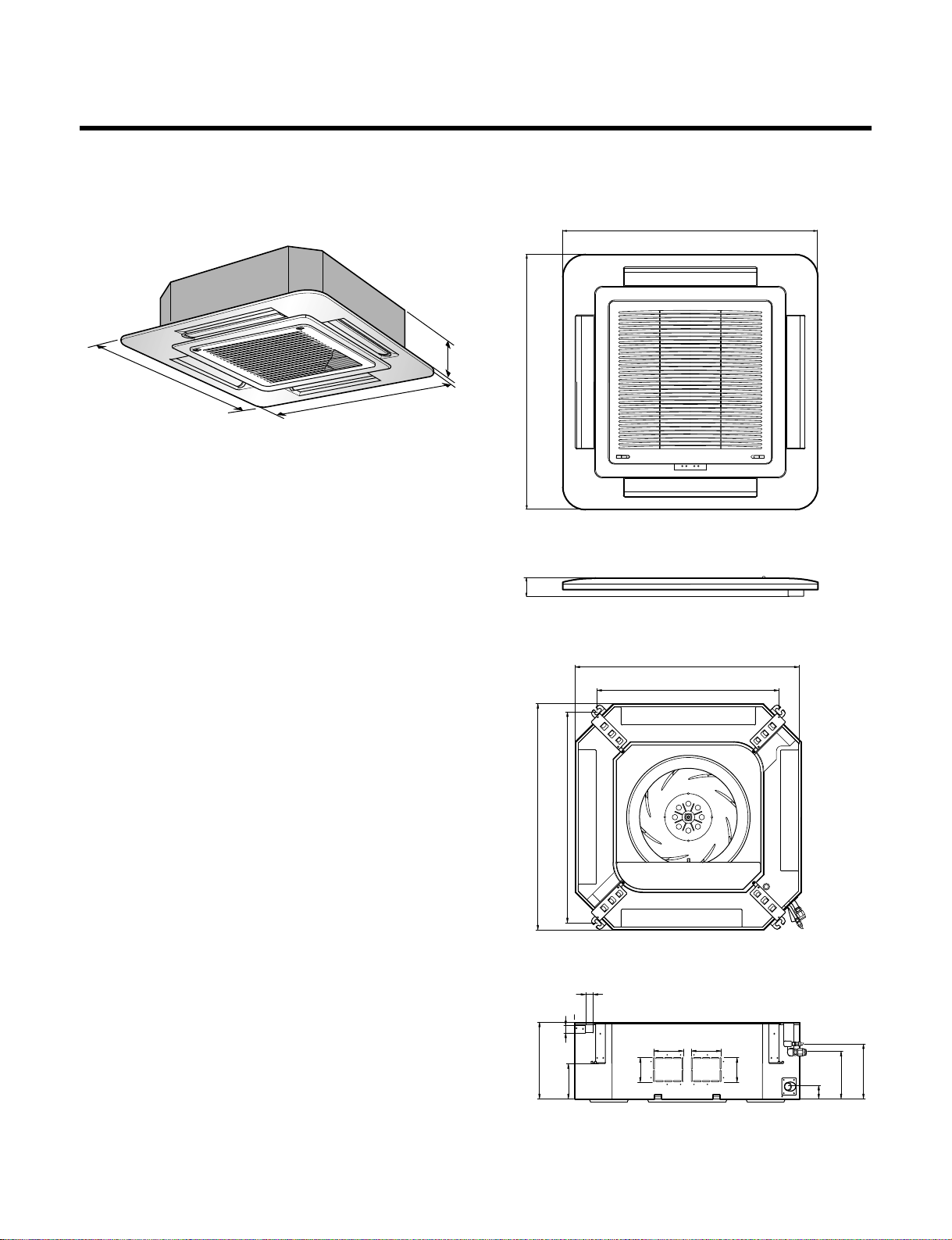
840*840*288 840*840*288 840*840*288 840*840*288
950*950*30 950*950*30 950*950*30 950*950*30
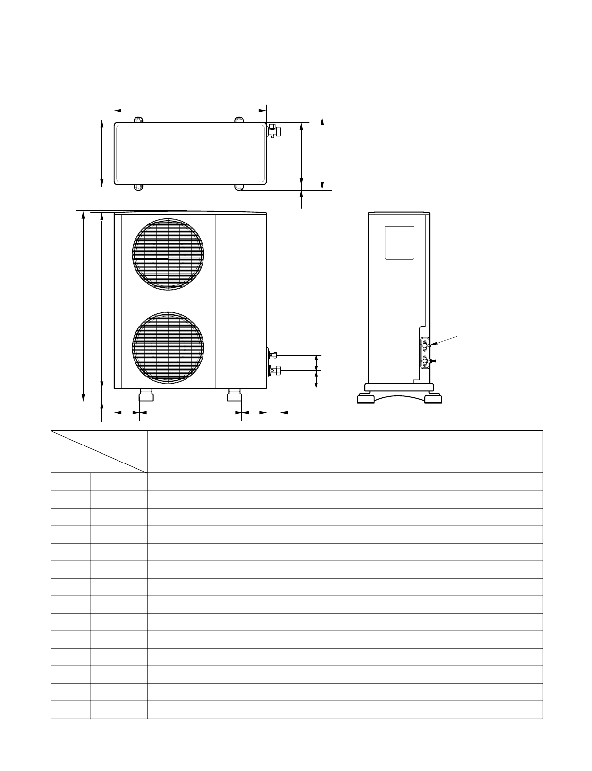
900*1,225*370 900*1,225*370 900*1,225*370 900*1,225*370
32 32 32 32
95 95 95 95
12 : 4*3.5 12 : 4*3.5 12 : 4*3.5 12 : 4*3.5
16 : 5*1.25 16 : 5*1.25 16 : 5*1.25 16 : 5*1.25
1/2(12.7) 1/2(12.7) 1/2(12.7) 1/2(12.7)
3/4(19.05) 3/4(19.05) 3/4(19.05) 3/4(19.05)
50 50 50 50
30 30 30 30
FoamPE/5mm FoamPE/5mm FoamPE/5mm FoamPE/5mm
Ø25 / 32 Ø25 / 32 Ø25 / 32 Ø25 / 32
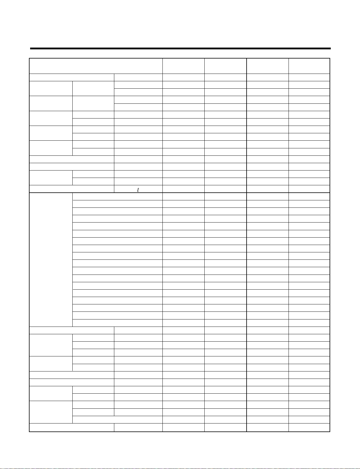
LT-D5480HA LT-D5480HL LT-D5480CA LT-D5480CL
Power Supply ø, V, Hz
Capacity Cooling kcal/h(W)
Btu/h
Heating kcal/h(W)
Btu/h
Input Cooling W
Heating W
Running Current Cooling A
Heating A
Starting Current Cooling A
Heating A
E.E.R kcal/h(W)
C.O.P W/W
Air Circulation Indoor m3/min
Outdoor m3/min
Moisture Removal / h
Air-Flow Direction Control
Heating Operation Mode
Fan Speeds (steps)
Auto Operation (Changeover)
Forced Operation
Jet Cool
Soft Dry Operation
Timer Delay Safety Function
Feature Air Deflection (Way)
Self Diagnosis
Hot start
Auto Restart
Air refresh (Hole)
High Ceiling
Group Control (Optional wiring)
Central Control
Wired remote controller (with weekly Program)
Plasma A/Cleaner
Refrigerant(R-22) Charge g
Dimensions Indoor mm
(W x D x H) Panel mm
Outdoor mm
Net Weight Indoor kg
Outdoor kg
Main Power Cord AWG#:P*mm2
Connection Cable AWG#:P*mm2
Service Valve Liquid Inch (mm)
Gas Inch (mm)
Installation Pipe Length (m)
Elevation (m)
Insulation(material/thickness)
Drain Hose(I.D/O.D) mm
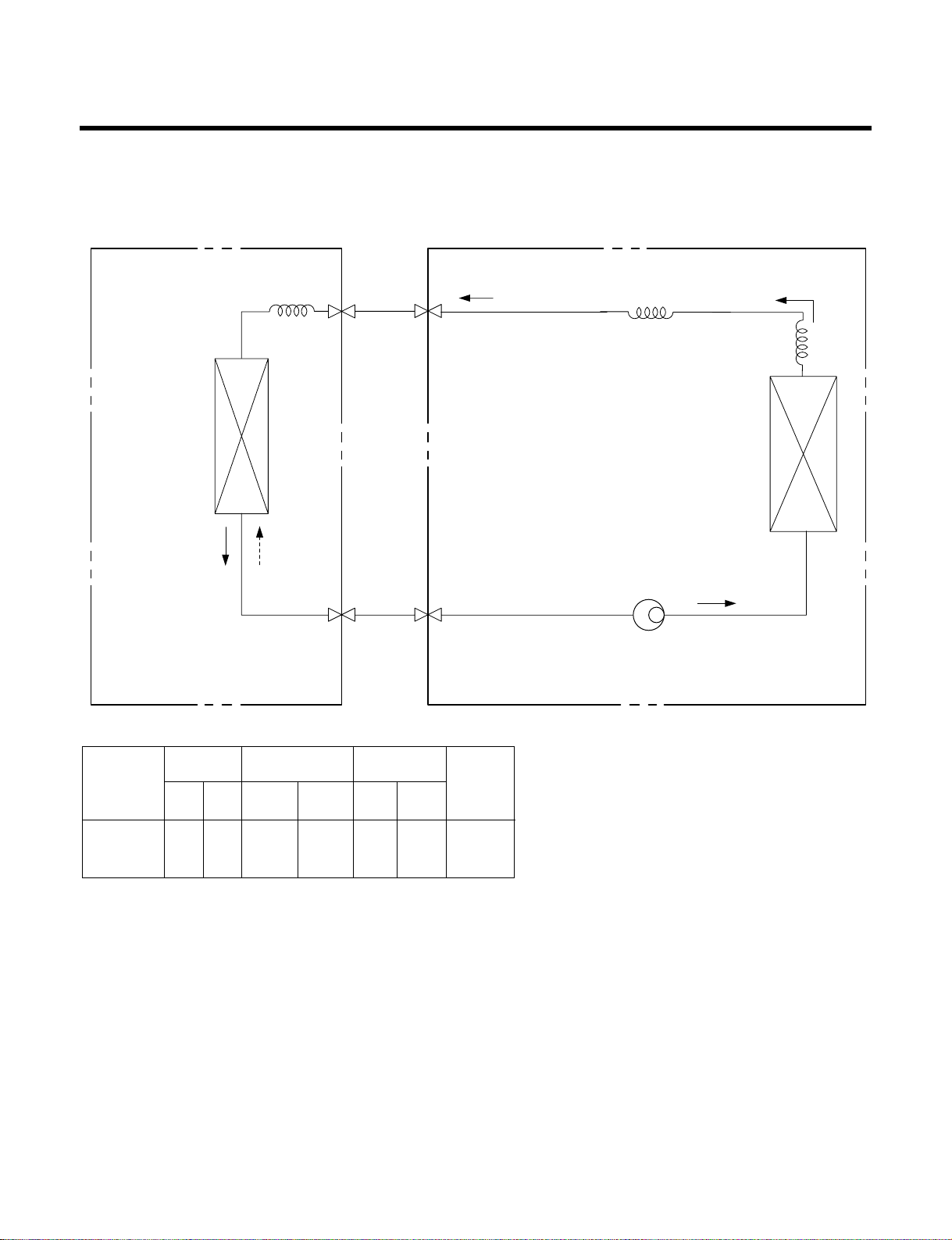
Product Specifications (Cooling & Heating)
–5–