Installation Method
10 Low Ambient Control Kit
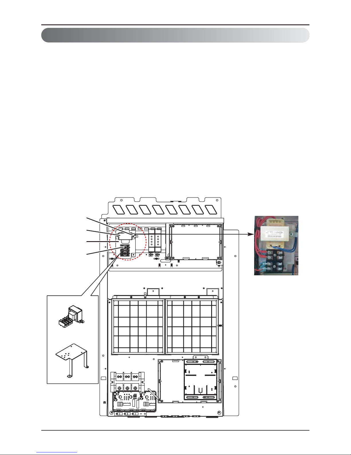
2. Transformer, Terminal Block Installation Method
①Shut off the main power of outdoor unit.
②Install the IO Module in the C/Box by using screws.
③Install the Bracket2 in the C/Box by using screws.
④Install the transformer on the Bracket2 by using screws.
⑤Install the terminal block on the Bracket2 by using screws.
⑥Connect the Main PCB(CN10) to IO Module(CN101) by using the cable assembly.
⑦Connect the blue cable of transformer to the Main PCB(JIG_N), brown cable of transformer to
the Main PCB(JIG_L).
⑧Connect the red cable of transformer to the terminal block (2Pin Yellow terminal block).
⑨Connect a power cable(DC 12V) to CN101(12V,GND) of IO Module.
⑩Connect the black cable of Damper Actuator to the terminal block and connect the cable of
IO Module(CN1_A0(GND(A-)) to the black cable of Damper Actuator.
⑪Connect the red cable of Damper Actuator to CN1_A0(A0_1(A+)) of IO Module.
⑫Set up the main function Dip S/W of IO Module.
(SW101 : L1,L2=On and L3,L4=Off / SW102 : L1,L2=Off)
⑬Set up the Dip S/W of Main Outdoor unit PCB. (Refer to page 21 for details)
⑭Turn on the main power of outdoor unit.
⑮Check the signal to CN1_A0(AO_01,GND) of IO Module and Air Damper.


 null")