EnglishDeutsch
 logo
Brands
  1. Home
  2. •
  3. Brands
  4. •
  5. LG
  6. •
  7. Air Conditioner
  8. •
  9. LG LSN5UR3F1 User manual

LG LSN5UR3F1 User manual

This manual suits for next models

3

Other LG Air Conditioner manuals

LG ARNU073CEA2 User manual

LG

LG ARNU073CEA2 User manual

LG LMNC092BTG0 User manual

LG

LG LMNC092BTG0 User manual

LG ARNU243VJA2 Instruction Manual

LG

LG ARNU243VJA2 Instruction Manual

LG LWHD2500ER User manual

LG

LG LWHD2500ER User manual

LG ARNU183TLC2 Instruction Manual

LG

LG ARNU183TLC2 Instruction Manual

LG LW8021IVSM User manual

LG

LG LW8021IVSM User manual

LG LSU181HSV User manual

LG

LG LSU181HSV User manual

LG UV36.NKD User manual

LG

LG UV36.NKD User manual

LG A5UW40GFA1 User manual

LG

LG A5UW40GFA1 User manual

LG LP0817WSR User manual

LG

LG LP0817WSR User manual

LG HBLG1004R User manual

LG

LG HBLG1004R User manual

LG A122NC NE1 User manual

LG

LG A122NC NE1 User manual

LG AMNH076LQL0 User manual

LG

LG AMNH076LQL0 User manual

LG LW6013ER User manual

LG

LG LW6013ER User manual

LG LS-E0960CL User manual

LG

LG LS-E0960CL User manual

LG LSN120HEV2 User manual

LG

LG LSN120HEV2 User manual

LG LW7014HR User manual

LG

LG LW7014HR User manual

LG LW1216HR User manual

LG

LG LW1216HR User manual

LG P09UCM0 User manual

LG

LG P09UCM0 User manual

LG Multi V ARNU093B1G2 User manual

LG

LG Multi V ARNU093B1G2 User manual

LG ABNH G A Series User manual

LG

LG ABNH G A Series User manual

LG BECON HVAC BACnet PQNFB17C1 Operating instructions

LG

LG BECON HVAC BACnet PQNFB17C1 Operating instructions

LG A4UQ306FA2 User manual

LG

LG A4UQ306FA2 User manual

LG A3UW24GFA0 User manual

LG

LG A3UW24GFA0 User manual

Popular Air Conditioner manuals by other brands

Panasonic CS-E12HKEW operating instructions

Panasonic

Panasonic CS-E12HKEW operating instructions

Mitsubishi Electric MSZ-GE60VA null

Mitsubishi Electric

Mitsubishi Electric MSZ-GE60VA null

Samsung AVMFC052EA0(4) null

Samsung

Samsung AVMFC052EA0(4) null

Haier HSU-09H03/R null

Haier

Haier HSU-09H03/R null

Haier HSU-24C03 null

Haier

Haier HSU-24C03 null

Mitsubishi Electric MSZ-GE22VA null

Mitsubishi Electric

Mitsubishi Electric MSZ-GE22VA null

Samsung AVMCH052CA1 null

Samsung

Samsung AVMCH052CA1 null

nedis ACMB1WT7 quick start guide

nedis

nedis ACMB1WT7 quick start guide

Daikin FCFV50A Operation manual

Daikin

Daikin FCFV50A Operation manual

Fujitsu Inverter ASBA30JFC operating manual

Fujitsu

Fujitsu Inverter ASBA30JFC operating manual

Toshiba RAS-M10SMUV-E installation manual

Toshiba

Toshiba RAS-M10SMUV-E installation manual

Daikin FXLQ20MAVE Operation manual

Daikin

Daikin FXLQ20MAVE Operation manual

CIAT Magister 2 Series Installation, Operation, Commissioning, Maintenance

CIAT

CIAT Magister 2 Series Installation, Operation, Commissioning, Maintenance

Bestron AAC6000 instruction manual

Bestron

Bestron AAC6000 instruction manual

Frigidaire FFRE0533S1E0 Use & care guide

Frigidaire

Frigidaire FFRE0533S1E0 Use & care guide

Samsung AS09HM3N user manual

Samsung

Samsung AS09HM3N user manual

Frigidaire CRA073PU11 use & care

Frigidaire

Frigidaire CRA073PU11 use & care

Soleus Air GB-PAC-08E4 operating instructions

Soleus Air

Soleus Air GB-PAC-08E4 operating instructions

https://manuals.online logo
https://manuals.online logoBrands
  • About & Mission
  • Contact us
  • Privacy Policy
  • Terms and Conditions

Copyright 2026 Manuals.Online. All Rights Reserved.

INSTALLATION MANUAL
AIR CONDITIONER
TYPE : WALL MOUNTED
Please read this installation manual completely before installing the product.
When the power cord is damaged, replacement work shall be
performed by authorized personnel on;y.
Installation work must be performed in accordance with the national wiring
standards by authorized personnel only.
Please retain this installation manual for
future reference after reading it thoroughly.
P/No. MFL39754859
LG Electronics India Pvt. Ltd.
Registered Office : A-27, Mohan Co-operative
Industrial Estate, Mathura Road, New Delhi-110044
Tel: 011-26991412, Fax: 011-26991410
www.lg.com
(Recommended 24°C is suitable for human body)
(Refer page no. 21 and 22 owner's manual)
6 Installation Parts provided with the Unit
6 Installation Parts you must purchase
7 Required Tools
8
10
11
11
12
14
15
17
18
20
Connecting the cable between indoor
unit and outdoor unit
Checking the drainage and forming the
piping
Air purging
Test running
Installation of Indoor & Outdoor Unit
Flaring Work and Connection of Piping
TABLE OF CONTENTS 5
INSTALLATION PARTS
INSTALLATION
6
8
Connection of piping (Indoor)
For right rear piping
For left rear piping
Connection of piping (Outdoor)
Type ‘A’ Screw
INSTALLATION PARTS
Installation parts provided with the unit
Type ‘A’ Screw Quantity Shape Others
4
Installation Plate
Type ‘B’ Screw
Holder Remote Control
1
2
1
Paper pattern for
installation.
Owner’s Manual
Installation Manual
•
•
•
Installation parts you must purchase
Paper pattern
for installation.
Owner’s
Manual
Installation
Manual
•
•
•
Sleeve
Bushing Sleave
Putty (Gum type sealer)
Vinyl tape (Wide)
Gas side piping
Liquid side piping
Additional drain pipe
Vinyl tape (Narrow)
Saddle
INSTALLATION PARTS
6
Installation parts you
must purchase
Installation plate
Sleeve
Bushing-Sleeve
Putty(Gum Type Sealer)
Bend the pipe as closely
on the wall as possible,
but be careful that it
doesn't break.
Vinyl tape (Wide)
Apply after carrying out a
drainahe test.
To carry out the drainage
test, remove the air filters
and pour water into the heat
exchanger.
Gas side piping
Liquid side piping
Additional drain pipe
Vinyl tape (Narrow)
Connecting cable: Cooling & Heat pump: 2EA
Cooling only: 1EA
More than 70cm
More than
10cm
More than
60cm
Saddle
More than
10cm
More than
5cm
Air filter
(Left and right
are identical)
More than
20cm
1
2
3
4
5
6
7
8
9
10
11
12
13
14
Installation Tools
S.No. Required Tools
Level Gauge
Screw Driver
Electric Drill
Hole Core Drill (Dia-70mm)
Flaring Tool Set
Specified torque wrenches 1.8kg.m, 4.2kg.m, 5.5kg.m, 6.6kg.m
(Different depending on model no.)
Spanner (Half Union)
A glass of water
Hexagonal Wrench
Gas-Leak Detector
Vacuum Pump
Gauge Manifold
Owner’s Manual
Thermometer
INSTALLATION TOOLS 7
INSTALLATION OF INDOOR & OUTDOOR UNIT
More than 10cm More than 10cm
More
than 60cm
More than 60cm
More than 70cm
Read completely, then follow step by step.
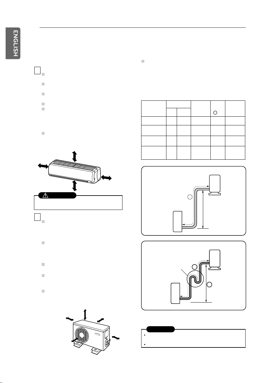
Capacity is based on standard length and maximum
allowance length is on the basis of reliability.
Oil trap should be installed every 5~7 meters.
In case more than 5m
A
Indoor unit
Oil trap
Outdoor unit
A
Indoor unit
Outdoor unit
A
Do not have any heat or steam near the
unit.
Select a place where there are no
obstacles in front of the unit.
Make sure that condensation drainage
can be conveniently routed away.
Do not install near a doorway.
Ensure that the space around the left and
right of the unit is more than 5cm. The
unit should be installed as high on the
wall as possible, allowing a minimum of
5cm from ceiling.
Use a stud finder to locate studs to
prevent unnecessary damage to the wall.
More than 5cm More than 5cm
More than 2.3m More than 5cm
Install the indoor unit on the wall where the height
from the floors more than 2.3 meters.
B
If an awning is built over the unit to
prevent direct sunlight or rain exposure,
make sure that heat radiation from the
condenser is not restricted.
Ensure that the space around the back
and sides is more than 10cm. The front of
the unit should have more than 70cm of
space.
Do not place animals and plants in the
path of the warm air.
Take the air conditioner weight into
account and select a place where noise
and vibration are minimum.
Select a place so that the warm air and
noise from the air conditioner do not
disturb neighbors.
Select the best location
Indoor Unit
CAUTION
Outdoor Unit
If the outdoor unit is installed on a roof structure, be
sure to level the unit. Ensure the roof structure and
anchoring method are adequate for the unit location.
Consult local codes regarding rooftop mounting.
Rooftop Installation
Piping length and elevation
CAUTION
INSTALLATION
8
Capacity
(Btu/h)
18K (60Hz)
24K Cooling
24K, 26K
Cooling & Heat Pump
5/8" 3/8" 3 to 5
Pipe Size
GAS LIQUID
Standard
Length
(m)
1/2" 1/4"
1/4"
3 to 5
3 to 5
20
20
20
20
5/8" 1/4" 3 to 5 20 20
20 20
Max.
length
(m)
A
Additional
Refrigerant
(g/m)
9K, 12K,
18K (50Hz)
9K 3/8"
B
Mount the installation plate horizontally by
aligning the centerline using a level.
A
Mount the installation plate on the wall with
four type A screws. If mounting the unit on a
concrete wall, use anchor bolts.
The wall you select should be strong and solid
enough to prevent vibration.
B
Measure the wall and mark the centerline. It
is also important to use caution concerning
the location of the installation plate-routing of
the wiring to power outlets is through the
walls typically. Drilling the hole through the
wall for piping connections must be done
safely.
Installation Plate
Marking-off line
Thread
Weight
Type "A" screw
Drill the piping hole with a ø70mm hole core
drill. Drill the piping hole at either the right or
the left with the hole slightly slanted to the
outdoor side.
Indoor
WALL
Outdoor
5-7mm
(0.2~0.3")
CAUTION
Make sure that the drilled hole in the wall is
properly sealed (using a proper sealant, for
example cement, plaster of paris etc.) after
passing the installation pipe, drainage pipe
and the inter connecting cable.
INSTALLATION OF INDOOR & OUTDOOR UNIT
How to fix installation plate Drill a hole in the wall
Outdoor Unit
Drain Pipe
Drain Pan
Drain pan along with drain pipe (as
shown below) can be used to drain
the water accumulated in the outdoor
during the Heat Mode.
Left rear piping Right rear piping
Hole center
ø70mm
"D" "C"
Usage of Drain Pan
(Heat Pump)
INSTALLATION 9
FLARING WORK AND CONNECTION OF PIPING
A
Use the piping kit accessory or the pipes
purchased locally.
Measure the distance between the indoor
and the outdoor unit.
Cut the pipes a little longer than measured
distance.
Cut the cable 1.5m longer than the pipe
length.
D
Carry out flaring work using flaring tool as shown
below.
Outside diameter
mm
ø6.35
ø9.52
ø12.7
ø15.88
inch
1/4
3/8
1/2
5/8
mm
0~0.5
0~0.5
0~0.5
0~1.0
A
Firmly hold copper pipe in a die in the
dimension shown in the table above.
B
Completely remove all burrs from the cut
cross section of pipe/tube.
Put the end of the copper tube/pipe in a
downward direction as you remove burrs in
order to avoid dropping burrs into the tubing.
E
Compare the flared work with figure below.
If flare is noted to be defective, cut off the flared
section and do flaring work again.
C
Remove flare nuts attached to indoor and
outdoor unit, then put them on pipe/tube
having completed burr removal.
(not possible to put them on after flaring
work)
Copper
pipe
90° Slanted Uneven Rough
Pipe
Reamer
Point down
Flare nut
Copper tube
Bar
Copper pipe
Clamp handle Red arrow mark
Cone
Yoke
Handle
Bar
"A"
Inclined
Inside is shiny without scratches.
Smooth all round
Even length
all round
Surface
damaged
Cracked Uneven
thickness
= Improper flaring =
Main cause for gas leakage is due to defect
in flaring work. Carry out correct flaring work
in the following procedure.
Flaring work Flaring work
Burrs removal
Check
Cut the pipes and the cable
Putting nut on
INSTALLATION
10