- 6 -
Copyright ©2008 LG Electronics. Inc. All right reserved.
Only for training and service purposes LGE Internal Use Only
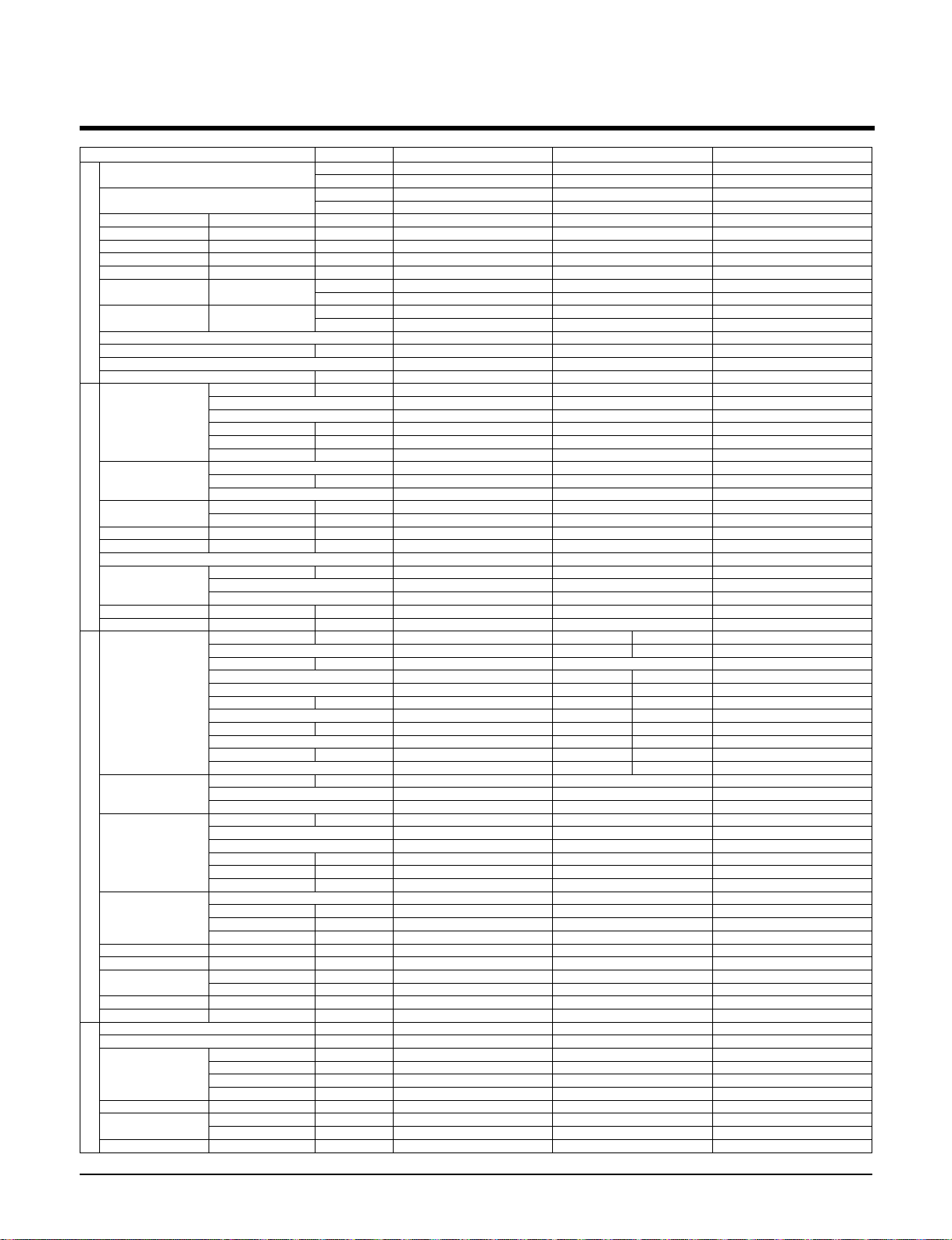
Items Unit
Cooling Capacity kcal/hr(W)
Btu/hr
Heating Capacity kcal/hr(W)
Btu/hr
Input Cooling/Heating W
Running Current Cooling/Heating A
Starting Current Cooling/Heating A
Power Supply Ø,V,Hz
Power Factor %
E.E.R Cooling kcal/hr W(W/W)
Btu/hr W
C.O.P Heating W/W(kcal/hr W)
Btu/hr W
Setting temperature range(cool/heat)
Dehumidification Rate l/h
Refrigerant Control
Refrigerant charge g(oz), type
Indoor fan motor Output w
Model
No. of Poles
Input W
Running Current A
Capacitor µF/Vac
Indoor Fan Type
No. Used / Diameter EA/inch(mm)
Motor Step
Indoor Fan RPM Cooling(H/M/L) rpm
Heating(H/M/L) rpm
Air Circulation Indoor (H/M/L) CMM(CFM)
Noise Level(Sound Press,1m)
Indoor(H/M/L) dB(A)±3
Temperature Controller
Indoor Coil Tube Size (OD) inch(mm)
Fins per inch
No. of Rows & Column
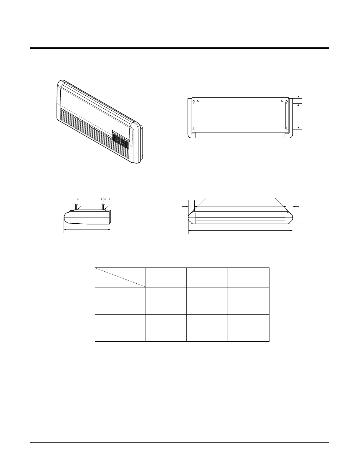
Dimensions (W*H*D) Indoor inch(mm)
Net Weight indoor kg(lbs)
Compressor Locked Rotor Amp. A
Type
Quantity No
Model
Maker
Capacity Btu/hr
Motor Type
Motor Input W
Oil Type
Oil Charge cc
O.L.P Type(model name)
Outdoor Coil Tube Size (OD) inch(mm)
Fins per inch
No. of Rows & Column
Outdoor fan motor Output W
Model
No. of Poles
Input W
Running Current A
Capacitor µF/Vac
Outdoor Fan Type
No. Used / Diameter EA/mm
Discharge Side/Top
Speed rpm
Air Circulation Outdoor CMM(CFM)
Noise Level(Sound Press,1m)
Outdoor dB(A)±3
SVC Valve Liquid inch(mm)
Gas inch(mm)
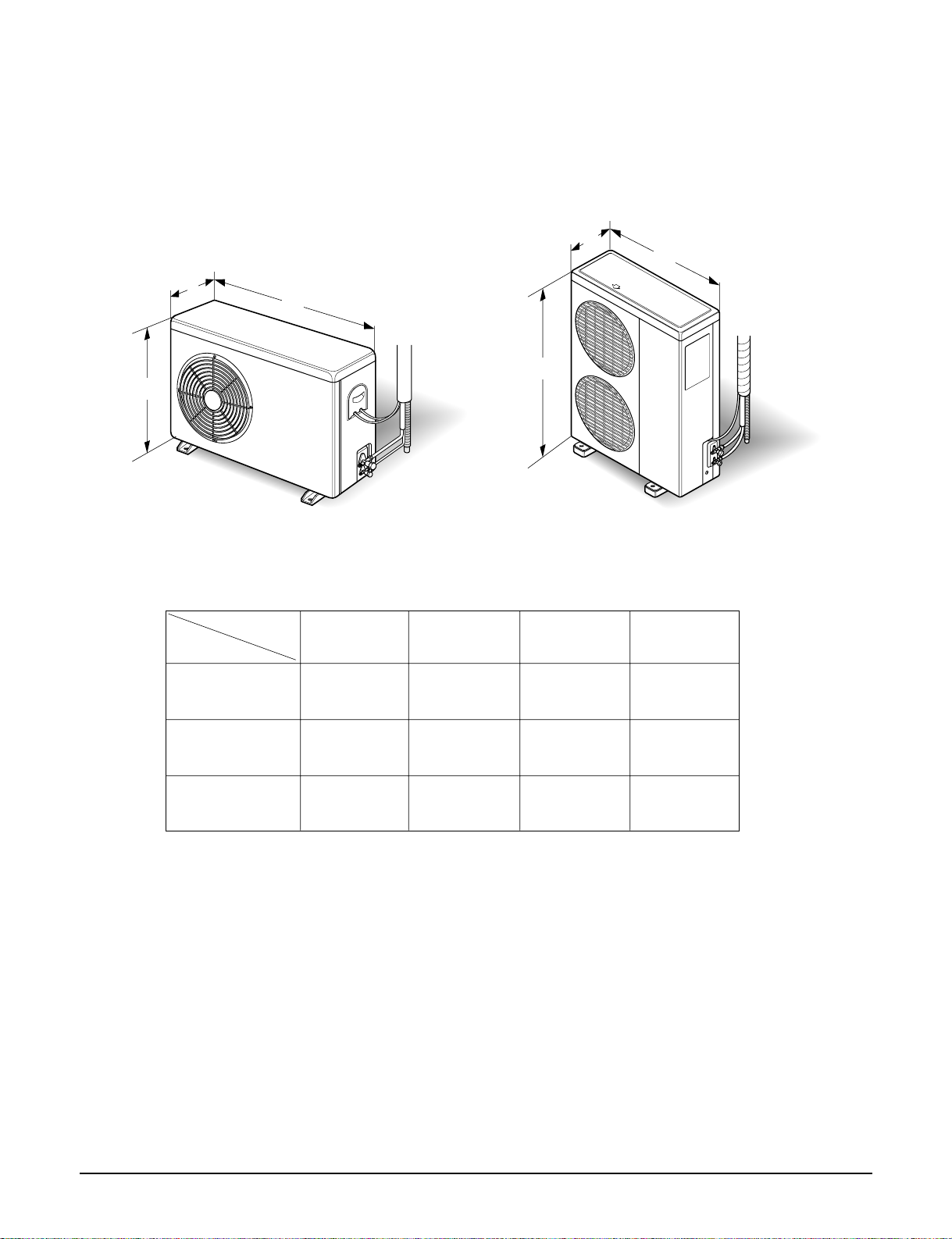
Dimensions (W*H*D) Outdoor inch(mm)
Net Weight Outdoor kg(lbs)
Power Supply Cable No.* mm2
Connecting Cable No.* mm2
Connecting Tube Liquid Side inch(mm)
(Ø. Socket Flare) Gas Side inch(mm)
Length, std m
Max length/elevation m
Drain hose(Inner Ø)
Indoor Unit/Outdoor Unit
mm
Packing Dimension Indoor(W*H*D) inch(mm)
Outdoor(W*H*D) inch(mm)
Stuffing Quantity With(Without) S/Parts 20/40ft
LV-C602HLA0 LV-C48BGLA0 LV-C60BHLA0
15,120/(17,584) 12,096(14,067) 15,120(17,584)
60,000 48,000 60,000
---
---
6,300 5,200 6,300
29 14.5 18.2
101 90 124
1, 220, 60 3, 220, 60 3, 220, 60
98.8 92.6 89.3
2.33(2.72) 2.22(2.57) 2.14(2.48)
9.25 8.8 8.5
---
---
18~30/- 18~30/- 18~30/-
7.67 5.2 7.1
Capillary Tube Capillary Tube Capillary Tube
4,050(145.4),R22 3,800(134),R22 4,680(165),R22
KHF2G4002 KHF2G4001 KHF2G4002
444
450 380 450
2.1 1.73 2.1
10.0/370 7.5/370 10.0/370
Centrifugal Centrifugal Centrifugal
4/164 3/164 4/164
333
1,450/1,150/1,000 1,470/1,240/1,040 1,450/1,150/1,000
---
37/31/27 36/32/27 37/31/27
61/59/57 59/57/55 61/59/57
Thermistor Thermistor Thermistor
9.7 9.7 9.7
13 13 13
4R 12C 4R 10C 4R 12C
1,550/650/292 1,550/650/272 1,550/650/292
63(137) 61(134) 63(137)
142 92 124
Reciprocating Reciprocating Scroll
111
CRN5-0500-PFV AVB5549EXT SR061RAA
Copeland TECUMSEH LG
62,700 48,096 62,000
Condenser Inducted PSC Three Phase Induction Motor
6,270 4,610 5,535
SUNISO 4GDID WITCO LP200T SUNISO 4GSI
1,774 2,000 1,800
Internal Internal Internal
0.375(9.52) 0.375(9.52) 0.375(9.52)
16 17 16
2R22C 2R 44C 2R 44C
90*2 90*2 90*2
AMR071B9 AMR071B9 AMR071B9
666
168*2 168*2 168*2
0.81*2 0.81*2 0.81*2
6.0/370 6.0/370 6.0/370
Propeller Propeller Propeller
2/382 2/382 2/382
Side Discharge Side Discharge Side Discharge
900 900 900
49(1,730)*2 49(1,730)*2 49(1,730)*2
62 62 62
1/2(12.7) 1 / 2 (12.7) 1 / 2 (12.7)
3/4(19.05) 3 / 4 (19.05) 3 / 4 (19.05)
35.43*48.23*14.57(900*1225*370) 35.43*48.23*14.57(900*1225*370) 35.43*48.23*14.57(900*1225*370)
95(209) 95(209) 95(209)
3*8.5 3*8.5 3*8.5
4*0.75 4*0.75 4*0.75
1/2(12.7) 1/2(12.7) 1/2(12.7)
3/4(19.05) 3/4(19.05) 3/4(19.05)
7.5 7.5 7.5
15/12.5 15/12.5 15/12.5
22.22/ 22.22 22.22/
1635/751/378 1635/751/358 1635/751/378
42.1*52.1*19.5(1070*1300*495) 42.1*52.1*19.5(1070*1300*495) 42.1*52.1*19.5(1070*1300*495)
21/44 21/45 21/44
General
Indoor
Outdoor
Outdoor


 null")