LG LWC183MGMJ1 User manual

ROOM AIR CONDITIONER
SERVICE MANUAL
CAUTION
- BEFORE SERVICING THE UNIT,
READ THE "SAFETY PRECAUTIONS" IN THIS MANUAL.
- ONLY FOR AUTHORIZED SERVICE
MODELS: LWC183MGMJ1, LWC183MSMM1, LWC183MGAB1
website http://biz.lgservice.com
e-mail http://www.lgeservice.com/techsup.html

—2—
1. PREFACE
1.1 SAFETY PRECAUTIONS................................................................................................................................3
1.2 INSULATION RESISTANCE TEST.................................................................................................................3
1.3 SPECIFICATIONS...........................................................................................................................................3
1.4 FEATURES .....................................................................................................................................................4
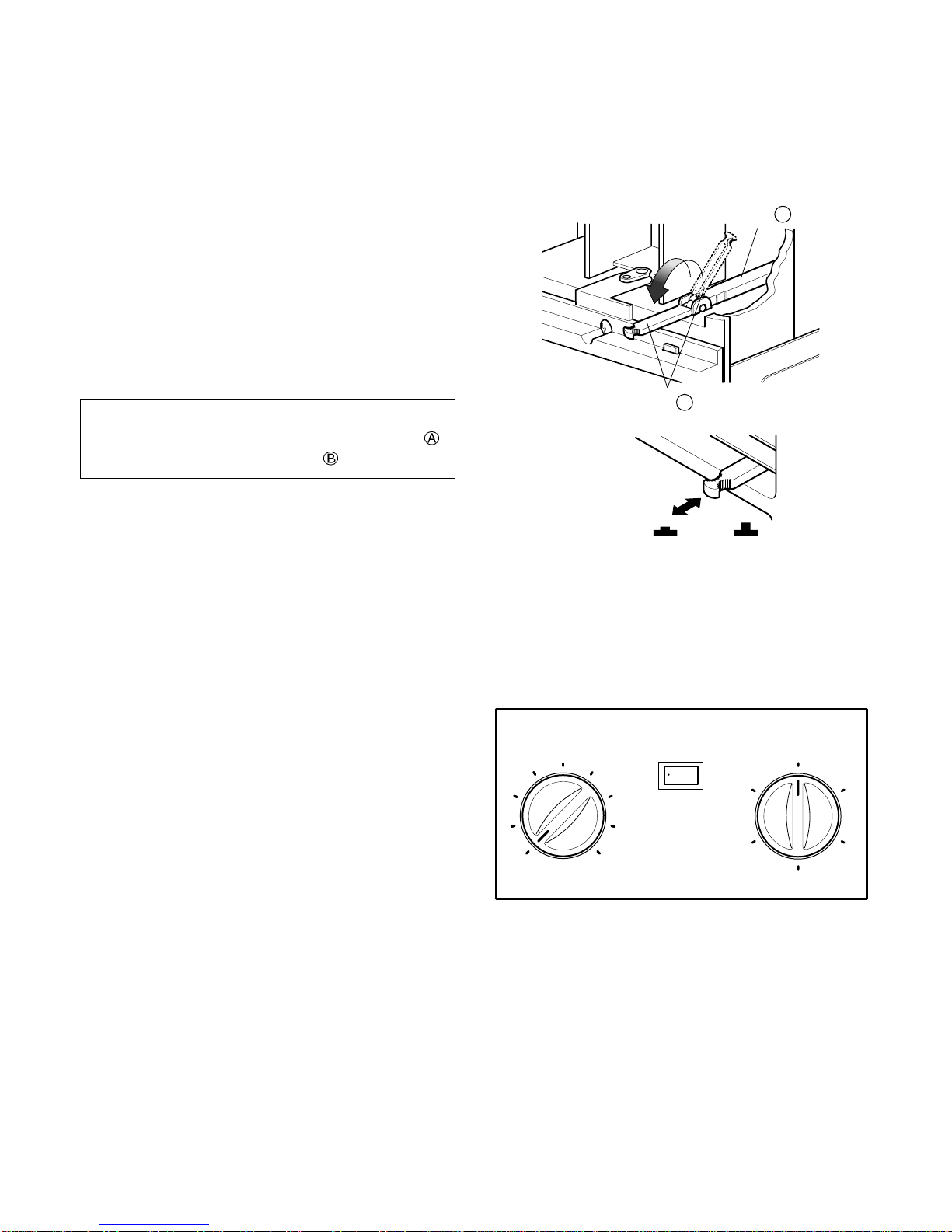
1.5 CONTROL LOCATIONS.................................................................................................................................4
2.
DISASSEMBLY INSTRUCTIONS
2.1 MECHANICAL PARTS....................................................................................................................................6
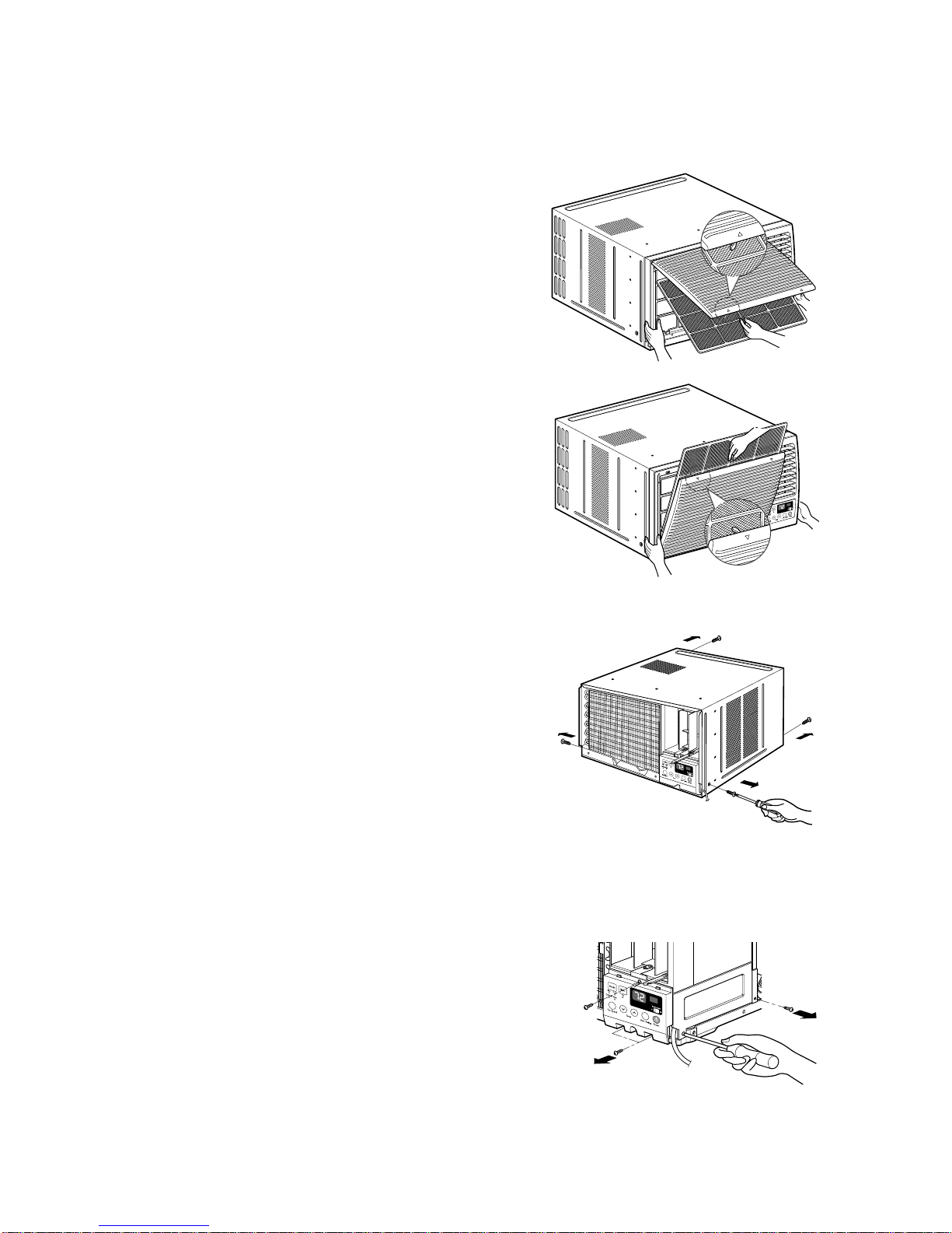
2.1.1 FRONT GRILLE.....................................................................................................................................6
2.1.2 CABINET................................................................................................................................................6
2.1.3 CONTROL BOX.....................................................................................................................................6
2.2 AIR HANDLING PARTS..................................................................................................................................7
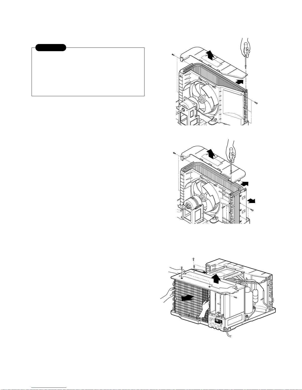
2.2.1 COVER (AT THE TOP)..........................................................................................................................7
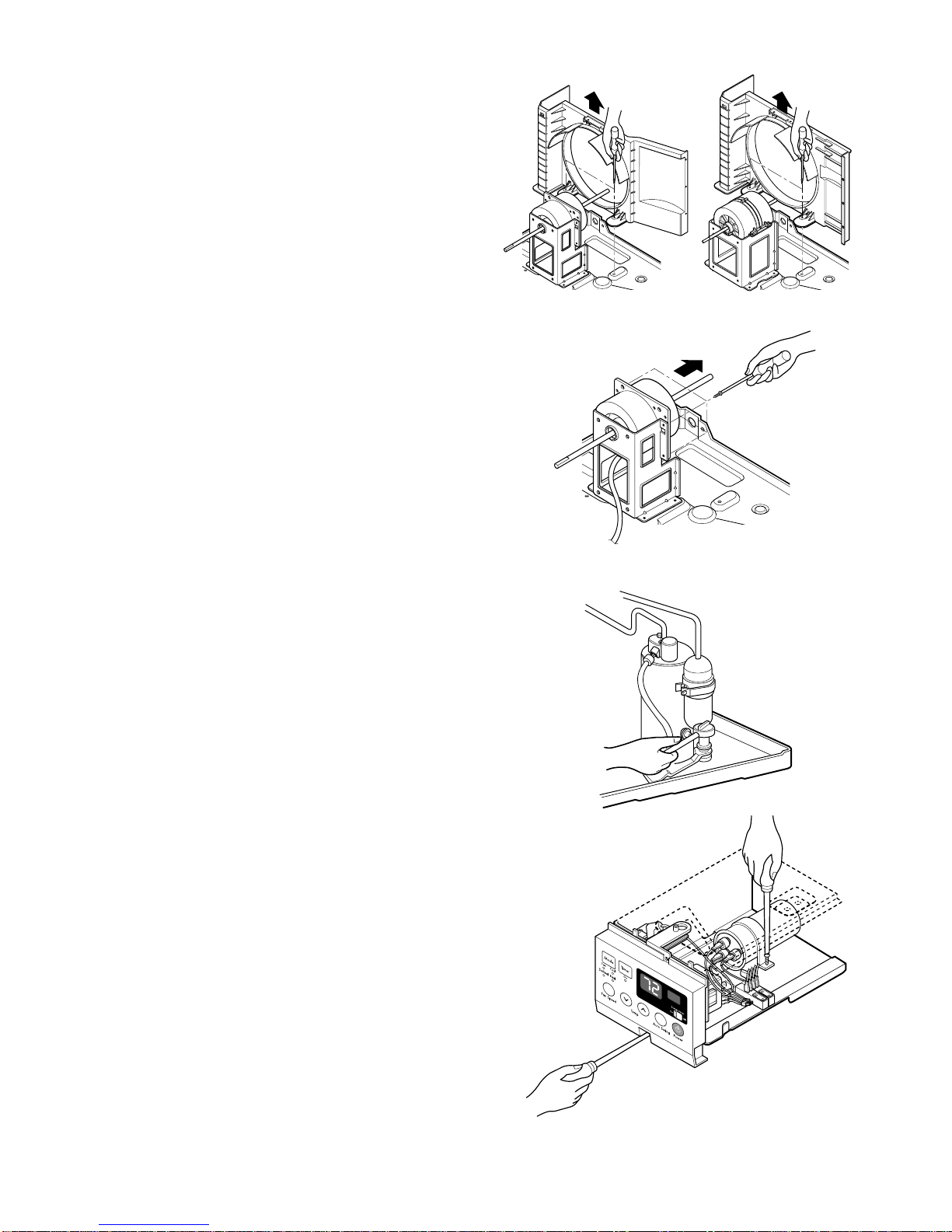
2.2.2 BLOWER................................................................................................................................................7
2.2.3 FAN........................................................................................................................................................7
2.2.4 SHROUD................................................................................................................................................8
2.3 ELECTRICAL PARTS .....................................................................................................................................8
2.3.1 MOTOR..................................................................................................................................................8
2.3.2 COMPRESSOR .....................................................................................................................................8
2.3.3 CAPACITOR ..........................................................................................................................................8
2.3.4 POWER CORD......................................................................................................................................9
2.3.5 THERMISTOR........................................................................................................................................9
2.3.6 SYNCHRONOUS MOTOR.....................................................................................................................9
2.4 REFRIGERATION CYCLE............................................................................................................................10
2.4.1 CONDENSER ......................................................................................................................................10
2.4.2 EVAPORATOR ....................................................................................................................................10
2.4.3 CAPILLARY TUBE...............................................................................................................................10
3.
INSTALLATION
3.1 HOW TO INSTALL THE UNIT.......................................................................................................................13
3.2
HOW TO USE THE REVERSIBLE INLET GRILLE
..................................................................................................................
13
3.3 WINDOW REQUIREMENTS.........................................................................................................................14
3.4 INSTALLATION KITS CONTENTS...............................................................................................................14
3.5 SUGGESTED TOOL REQUIREMENTS.......................................................................................................15
3.6 CABINET INSTALLATION ............................................................................................................................16
4.
TROUBLESHOOTING GUIDE
4.1 OUTSIDE DIMENSIONS...............................................................................................................................18
4.2 PIPING SYSTEM...........................................................................................................................................18
4.3 TROUBLESHOOTING GUIDE......................................................................................................................19
5. SCHEMATIC DIAGRAM
5.1 CIRCUIT DIAGRAM......................................................................................................................................28
5.2 ELECTRONIC CONTROL DEVICE ..............................................................................................................29
5.3
COMPONENTS LOCATION(FOR MAIN P.C.B ASM
).......................................................................................................30
5.4
COMPONENTS LOCATION(FOR DISPLAY P.C.B ASM)
.......................................................................................................30
6. EXPLODED VIEW..................................................................................................................................31
7. REPLACEMENT PARTS LIST........................................................................................................32
CONTENTS

—3—
1.1 SAFETY PRECAUTIONS
1. When servicing, set the POWER of CONTROL BOARD to
Off and unplug the power cord.
2. Observe the original lead dress.
If a short circuit is found, replace all parts which have been
overheated or damaged by the short circuit.
3. After servicing, make an insulation resistance test to
prevent the customer's exposure to shock hazards.
1.2 INSULATION RESISTANCE TEST
1. Unplug the power cord and connect a jumper between 2
pins (black and white).
2. The grounding conductor (green or green and yellow) is to
be open.
3. Measure the resistance value with an ohm meter between
the jumpered lead and each exposed metallic part on the
equipment at all Mode [except POWER OFF].
4. The value should be over 1 MΩ.
1. PREFACE
This service manual provides various service information, including the mechanical and electrical parts, etc.
This room air conditioner was manufactured and assembled under a strict quality control system.
The refrigerant is charged at the factory. Be sure to read the safety precautions prior to servicing the unit.
1.3 SPECIFICATIONS
POWER SUPPLY
COOLING CAPACITY
INPUT
RUNNING CURRENT
REFRIGERANT(R-22)
OPERATING INDOOR
TEMPERATURE OUTDOOR
EVAPORATOR
CONDENSER
FAN,INDOOR
FAN,OUTDOOR
FAN SPEEDS,FAN/COOLING
FAN MOTOR
OPERATION CONTROL
ROOM TEMP.CONTROL
AIR DIRECTION CONTROL
CONSTRUCTION
PROTECTOR COMPRESSOR
FAN MOTOR
POWER CORD
DRAIN SYSTEM
NET WEIGHT
OUTSIDE DIMENSION (inch)
(mm)
LWC183MGMJ1 LWC183MSMM1 LWC183MGAB1
MODELS
ITEMS
* DB:Dry Bulb
**
WB:Wet Bulb
NOTE : Specifications are subject to minor change without notice for further improvement.
1Ø,208/230V,60Hz
17,500/18,000
1,800/1,850
9.0/8.3
625g(22oz)
26.7(DB),19.4(WB)
35(DB),23.9(WB)
2 ROW 15STACKS
2 ROW 19STACKS
TURBO
PROPELLER TYPE FAN WITH SLINGER-RING
3/3 2/3
6POLES
WIRELESS REMOCON ROTARY SWITCH
THERMISTOR THERMOSTAT
VERTICAL LOUVER(RIGHT&LEFT)
HORIZONTAL LOUVER (UP&DOWN)
SLIDE IN-OUT CHASSIS
INTERNAL OVERLOAD PROTECTOR
INTERNAL THERMAL PROTECTOR
3 WIRE WITH GROUNDING
CORD-CONNECTED TYPE (ATTACHMENT PLUG:OPTION)
DRAIN PIPE OR SPLASHED BY FAN SLINGER
130/60
26 x 16 27/32 x 26 9/16
660 x 428 x 675

1.4 FEATURES
• Designed for cooling only.
• Powerful and quiet cooling.
• Slide-in and slide-out chassis for the simple installation
and service.
• Reversible inlet grille.
1.5 CONTROL LOCATIONS
• VENTILATION
The ventilation lever must be in the CLOSE position in
order to maintain the best cooling conditions.
When a fresh air is necessary in the room, set the
ventilation lever to the OPEN position.
The damper is opened and room air is exhausted.
Precaution: The Remote Control unit will not function
properly if strong light strikes the sensor
window of the air conditioner or if there
are obstacles between the Remote
Control unit and the air conditioner.
• Side air-intake, side cooled-air discharge.
• Built in adjustable THERMISTOR.
• Washable one-touch filter.
• Compact size.
• THERMOSTAT
Thermostat will automatically control the
temperature of the room. Select the higher number
for the lower temperature of the room. The
temperature is selected by positioning the knob to
the desired position.
The 5or 6position is a normal setting for average
conditions.
• OPERATION
OFF : Turns the air conditioner off.
MED FAN : Permits the
medium
fan speed operation
without cooling.
LOW FAN : Permits the low fan speed operation
without cooling.
HIGH COOL: Permits cooling with the high fan speed
operation.
MED COOL : Permits cooling with the medium fan
speed operation.
LOW COOL: Permits cooling with the low fan speed
operation.
•AUTOSWING
ON : Air swing is operated while OPERATION knob
is set to the COOL position.
OFF :Stops the operation of air swing.
—4—
Part A
Part B
VENTCLOSE OPEN
Med
Fan
Off
Low
Fan
High
Cool
Med
Cool
Low Cool
Operation
6
7
8
9
5
1
2
3
4
Thermostat
Off On
Auto Swing
NOTE: Before using the ventilation feature, make
the lever, as shown. First, pull down part
to horizontal line with part .

—5—
POWER BUTTON
Operation starts, when this button is pressed and stops when you press the button again.
OPERATION MODE SELECTION BUTTON
Select Cooling, or Fan or Dehumid mode with button. (Dehumid mode is not to all models.)
ON/OFF TIMER BUTTON
Set the time of starting and stopping operation. The timer is set by 1 hour.
FAN SPEED SELECTOR
Select the fan speed in two steps (Low or High).
ROOM TEMPERATURE SETTING BUTTON
Control the room temperature within a range of 16°Cto30°C.
AUTO RESTART SWITCH (NOT TO ALL MODELS)
In failure of electric power, if the switch is set to "ON", the unit runs as previous setting operation when power returns.
AUTO SWING BUTTON
Control the horizontal air direcion by air swing system.
SIGNAL RECEIVER
6
6
7
7
8
8
Precaution: The Remote Control unit will not function properly if strong light strikes the sensor window of the air
conditioner or if there are obstacles between the Remote Control unit and the air conditioner.
REMOTE CONTROL
DISPLAY
2
2
1
5
4
2
3
1
6
8
4
5 7
7
Power
TimerFanMode
Auto
Restart Auto
Swing
Temp
3
7
6
2
4
5 1 8

—6—
2.1 MECHANICAL PARTS
2.1.1 FRONT GRILLE
1. Open the inlet grille upward or downward.
2. Remove the screw which fastens the front grille.
3. Pull the front grille from the right side.
4. Remove the front grille. (See Fig. 1)
5. Re-install the component by referring to the
removal procedure.
NOTE: Mark ∆of inlet grille means opening direction.
2.1.2 CABINET
1. After disassembling the FRONT GRILLE, remove
the screws which fasten the cabinet at both sides.
Keep these for later use.
2. Remove the two screws which fasten the cabinet
at back. (See Fig. 2)
3. Pull the base pan forward.
2.1.3 CONTROL BOX
1. Remove the front grille. (Refer to section 2.1.1)
2. Pull the base pan forward so that you can remove
the 2 screws which fasten the cover control at the
right side. (See Fig. 3)
3. Remove the 3 screws which fasten the control
box. (See Fig. 3)
4. Discharge the capacitor by placing a 20,000 ohm
resistor across the capacitor terminals.
5. Disconnect two wire housings in the control box.
6. Pull the control box forward completely.
7. Re-install the components by referring to the
removal procedure. (See Fig. 3)
(Refer to the circuit diagram found on page 23 in
this manual and on the control box.)
2. DISASSEMBLY INSTRUCTIONS
—Before the following disassembly, POWER SWITCH is set to OFF and disconnected the power cord.
Figure 1
Figure 2
Figure 3

—7—
2.2 AIR HANDLING PARTS
2.2.1 COVER (AT THE TOP)
1. Remove the front grille. (Refer to section 2.1.1)
2. Remove the cabinet. (Refer to section 2.1.2)
3. Remove 11 screws which fasten the brace and
covers.
4. Remove the covers and the brace. (See Fig. 4)
5. Re-install the components by referring to the
removal procedure, above.
2.2.2 BLOWER
1. Remove the cover. (Refer to section 2.2.1)
2. Remove the 3 screws which fasten the
evaporator at the left side and the top side.
(See Fig. 4)
3. Move the evaporator sideward carefully.
4. Remove the orifice from the air guide carefully.
5. Remove the clamp spring which is clamped to the
boss of blower by hand plier. (See Fig. 5)
6. Pull the blower outward, without touching blades.
(See Fig. 6)
7. Re-install the components by referring to the
removal procedure, above.
2.2.3 FAN
1. Remove the cabinet. (Refer to section 2.1.2)
2. Remove the brace and shroud cover.
(Refer to section 2.2.1)
3. Remove the 5 screws which fasten the condenser.
4. Move the condenser sideways carefully.
5. Remove the clamp which secures the fan.
6. Remove the fan. (See Fig. 7)
7. Re-install the components by referring to the
removal procedure, above.
Figure 4 (a) Figure 4 (b)
Figure 5
Figure 6
Figure 7 (a) Figure 7 (b)

—8—
2.2.4 SHROUD
1. Remove the fan. (Refer to section 2.2.3)
2. Remove the 2 screws which fasten the shroud.
3. Remove the shroud. (See Fig. 8)
4. Re-install the component by referring to the
removal procedure, above.
2.3 ELECTRICAL PARTS
2.3.1 MOTOR
1. Remove the cabinet. (Refer to section 2.1.2)
2. Remove the cover control and disconnect a wire
housing in control box. (Refer to section 2.1.3)
3. Remove the blower. (Refer to section 2.2.2)
4. Remove the fan. (Refer to section 2.2.3)
5. Remove the 4 screws which fasten the motor.
(See Fig. 9)
6. Remove the motor.
7. Re-install the components by referring to the
removal procedure, above.
2.3.2 COMPRESSOR
1. Remove the cabinet. (Refer to section 2.1.2)
2. Discharge the refrigerant by using a Refrigerant
Recovery System.
3. Disconnect the 3 leads from the compressor.
4. After purging the unit completely, unbraze the
suction and discharge tubes at the compressor
connections.
5. Remove the 3 nuts and the 3 washers which
fasten the compressor. (See Fig. 10)
6. Remove the compressor.
7. Re-instill the components by referring to the
removal procedure, above.
2.3.3 CAPACITOR
1. Remove the control box. (Refer to section 2.1.3)
2. Remove the screw which fasten the display panel.
3. Disconnect the 2 leads from the rocker switch and
remove the panel.
4. Remove a screw and unfold the control box.
(See Fig. 11)
5. Remove the screw and the clamp which fastens
the capacitor. (See Fig. 11)
6. Disconnect all the leads of capacitor terminals.
7. Re-install the components by referring to the
removal procedure, above.
Figure 8 (a) Figure 8 (b)
Figure 9
Figure 10
Figure 11

—9—
2.3.4 POWER CORD
1. Remove the control box. (Refer to section 2.1.3)
2. Unfold the control box. (Refer to section 2.3.3)
3. Disconnect the grounding screw from the control
box.
4. Disconnect 2 receptacles.
5. Remove a screw which fastens the clip cord.
6. Pull the power cord. (See Fig. 12)
7. Re-install the component by referring to the
removal procedure, above.
(Use only one ground-marked hole for ground
connection.)
8. If the supply cord of this appliance is damaged, it
must be replaced by the special cord.
(The special cord means the cord which has the
same specification marked on the supply cord
fitted to the unit.)
2.3.5 THERMISTOR
1. Remove the control box. (Refer to section 2.1.3)
2. Unfold the control box. (Refer to section 2.3.3)
3. Disconnect the thermistor terminals from main
P.W.B assembly.
4. Remove the thermistor.
5. Re-install the components by referring to the
removal procedure above. (See Figure 13)
2.3.6 SYNCHRONOUS MOTOR
1. Remove the control box. (Refer to section 2.1.3)
2. Unfold the control box. (Refer to section 2.3.3)
3. Remove the crankshaft.
4. Disconnect all the leads of the synchronous
motor.
5. Remove the 2 screws which fasten the
synchronous motor. (See Fig. 14)
6. Re-install the components by referring to the
removal procedure, above.
Figure 13
Figure 12
Figure 14

—10—
2.4 REFRIGERATION CYCLE
2.4.1 CONDENSER
1. Remove the cabinet. (Refer to section 2.1.2)
2. Remove the brace and the shroud cover.
(Refer to section 2.2.1)
3. Remove the 5 screws which fasten the condenser.
4. After discharging the refrigerant completely,
unbraze the interconnecting tube at the condenser
connections.
5. Remove the condenser.
6. Re-install the components by referring to notes.
(See Fig. 15)
2.4.2 EVAPORATOR
1. Remove the cabinet. (Refer to section 2.1.2)
2. Remove the top cover and the brace.
(Refer to section 2.2.1)
3. Discharge the refrigerant completely.
4. Remove the 3 screws which fasten the evaporator
at the left side and the top side.
5. Move the evaporator sideward carefully and then
unbraze the interconnecting tube at the evaporator
connectors.
6. Remove the evaporator.
7. Re-install the components by referring to notes.
(See Fig. 16)
2.4.3 CAPILLARY TUBE
1. Remove the cabinet. (Refer to section 2.1.2)
2. Remove the brace. (Refer to section 2.2.1)
3. After discharging the refrigerant completely,
unbraze the interconnecting tube at the capillary
tube.
4. Remove the capillary tube.
5. Re-install the components by referring to notes.
Figure 15 (a)
Figure 15 (b)
Figure 16
Discharge the refrigerant system using FreonTM
Recovery System.
If there is no valve to attach the recovery system,
install one (such as a WATCO A-1) before
venting the FreonTM. Leave the valve in place
after servicing the system.
CAUTION

—11—
—Replacement of the refrigeration cycle.
1. When replacing the refrigeration cycle, be sure to
discharge the refrigerant system using a FreonTM
recovery System.
If there is no valve to attach the recovery system,
install one (such as a WATCO A-1) before venting
the FreonTM. Leave the valve in place after
servicing the system.
2. After discharging the unit completely, remove the
desired component, and unbrace the pinch-off
tubes.
3. Solder service valves into the pinch-off tube ports,
leaving the valves open.
4. Solder the pinch-off tubes with Service valves.
5. Evacuate as follows.
1) Connect the vacuum pump, as illustrated Fig.
17A.
2) Start the vacuum pump, slowly open manifold
valves A and B with two full turns
counterclockwise and leave the valves closed.
The vacuum pump is now pulling through valves
A and B up to valve C by means of the manifold
and entire system.
3) Operate the vacuum pump for 20 to 30 minutes,
until 600 microns of vacuum is obtained. Close
valves A and B, and observe vacuum gauge for
a few minutes. A rise in pressure would
indicate a possible leak or moisture remaining in
the system. With valves A and B closed, stop
the vacuum pump.
4) Remove the hose from the vacuum pump and
place it on the charging cylinder. See Fig. 17B.
Open valve C.
Discharge the line at the manifold connection.
5) The system is now ready for final charging.
6. Recharge as follows :
1) Refrigeration cycle systems are charged from the
High-side. If the total charge cannot be put
in the High-side, the balance will be put in the
suction line through the access valve which you
installed as the system was opened.
2)
Connect the charging cylinder as shown in Fig. 17B.
With valve C open, discharge the hose at the
manifold connection.
3) Open valve A and allow the proper charge to
enter the system. Valve B is still closed.
4) If more charge is required, the high-side will not
take it. Close valve A.
5) With the unit running, open valve B and add the
balance of the charge.
a. Do not add the liquid refrigerant to the Low-
side.
b. Watch the Low-side gauge; allow pressure to
rise to 30 lbs.
c. Turn off valve B and allow pressure to drop.
d. Repeat steps B and C until the balance of the
charge is in the system.
6) When satisfied the unit is operating correctly,
use the pinch-off tool with the unit still running
and clamp on to the pinch-off tube. Using a tube
cutter, cut the pinch-off tube about 2 inches from
the pinch-off tool. Use sil-fos solder and solder
pinch-off tube closed. Turn off the unit, allow it to
set for a while, and then test the leakage of the
pinch-off connection.
NOTES
If high vacuum equipment is used, just crack
valves A and B for a few minutes, then open
slowly with the two full turns counterclockwise.
This will keep oil from foaming and being
drawn into the vacuum pump.
CAUTION

—12—
Equipment needed: Vacuum pump, Charging cylinder, Manifold gauge, Brazing equipment. Pinch-off tool
capable of making a vapor-proof seal, Leak detector, Tubing cutter, Hand Tools to remove components, Service
valve.
A
COMPOUND GAUGE
EVAPORATOR
(LOW PRESSURE SIDE)
COMPRESSOR
CAPILLARY TUBE
CONDENSER
(HIGH PRESSURE SIDE)
SEE INSETS
BELOW
MANIFOLD
GAUGE
B
Figure 17A-Pulling Vacuum Figure 17B-Charging
A
B
EXTERNAL
VACUUM PUMP
A
CHARGING
CYLINDER
LOW HI
B
C

—13—
3. TROUBLESHOOTING GUIDE
3.1 OUTSIDE DIMENSIONS
675(770) 660
428
CAPILLARY TUBE
COMPRESSOR
BLOWER
EVAPORATOR COIL
CONDENSER COIL
FAN
MOTOR
: REFRIGERANT FLOW
3.2 PIPING SYSTEM
Following is a brief description of the important components and their functions in the refrigeration system.
Refer to Fig. 18 to follow the refrigeration cycle and the flow of the refrigerant in the cooling cycle.
MOTOR
COMPRESSOR
OIL
(LIQUID REFRIGERANT)
CAPILLARY TUBE
OUTSIDE COOLING
AIR FOR REFRIGERANT
PASS THROUGH
SUCTION LINE
COOL LOW PRESSURE VAPOR
COOLED
AIR
COMPLETE LIQUID
BOIL OFF POINT
LIQUID
PRESSURE
DROP
ROOM AIR HEAT LOAD
VAPOR INLET HOT
DISCHARGED
AIR
LIQUID OUTLET
HIGH PRESSURE VAPOR
LIQUID PEFRIGERANT
LOW PRESSURE VAPOR
ROOM AIR CONDITIONER
EVAPORATOR COILS CONDENSER COILS
CYCLE OF REFRIGERATION
Figure 18

—14—
3.3 TROUBLESHOOTING GUIDE
In general, possible trouble is classified in two causes.
The one is called Starting Failure which is caused from an electrical defect, and the other is Ineffective Air
Conditioning caused by a defect in the refrigeration circuit and improper application.
Unit runs but poor cooling
Ineffective Cooling
Check of outdoor coil
(heat exchanger) & the fan
operation.
Check gas leakage.
Repair gas leak.
Replacement of unit if the
unit is beyond repair.
Satisfactory operation with
temperature difference of
inlet & outlet air ; 44.6~50°F
Check heat load increase.
Unexpected residue
Overloaded Circuit
Check of inside gas
pressure.
Adjusting of refrigerant
charge
Malfunction of compressor
Replacement of
compressor
Check of cold air circulation
for smooth flow.
Dirty indoor coil
(Heat exchanger)
Malfunction of fan
Clogged of air filter
Obstruction at air outlet
Correct above trouble
Stop of auto air-swing
Check clogging in
refrigeration circuit.
Repair clogging in
refrigeration circuit.

—15—
Fails to Start
Check of circuit breaker
and fuse.
Check of control panel.
Only fan fails to start.
Improper wiring.
Defect of fan motor
capacitor.
Irregular motor resistance
( ).
Irregular motor insulation
( ).
Replacement of fan motor
Regular but fails to start
Replacement of compressor
(locking of rotor, metal)
Improper thermistor setting
Loose terminal connection.
Improper wiring
Irregular motor resistance ( )
Irregular motor insulation ( )
Replacement of compressor
(Motor damaged)
Drop of power voltage.
Check capacitor.
Replacement.
Only compressor fails to
start.
Defect of compressor
capacitor.
Check of power source.
Check of control switch
setting.

Is the Trans output power the
same as specified?
Is the Trans output power
about AC 14V? Is shorted the Trans. output?
Is output Voltage of IC01D
DC 12V?
Is output Voltage of IC02D
DC 5V?
Is the voltage No.18 of Micom
DC 5V?
Exchange Main P.W.B Ass'y.
Is the
connection between
Main and Display
all right?
Is the reset circuit all right?
(The No.14 of Micom
is 5V.)
•
Check the Fuse.
•
Check the wiring diagram.
•
Check the Main
P.W.B pattern.
•Exchange the Trans.
•
Exchange D02D~D05D.
•Exchange IC01D.
•Exchange IC02D.
•Exchange IC01A.
•Connect connector
exactly.
•Check the
P.W.B
pattern.
NO
NO
NO
NO
NO
NO
NO
YES
YES
YES
YES
YES
YES
YES
NO
YES
ELECTRIC PARTS TROUBLESHOOTING GUIDE:
MODEL: LWC183MGMJ1, LWC183MSMM1
Possible Trouble 1 •The unit does not operate.
—16—

—17—
Is Temp.
setting set lower than Room
Temp.-0.5°C?
Is the voltage No.10
of IC01M 0V?
•Exchange IC01M.
•Set the Temp. setting to higher Temp.
•Wait 3 Minutes
Is the Unit for 3 minutes
delay?
•Exchange MAIN
P.W.B Ass'y.
Is the voltage N0.7 of
IC01M DC 5V?
•Check the RY-COMP.
•Check the wiring
Diagram.
NO
NO
NO NO
YES YES
YES
YES
Possible Trouble 2 •The compressor does not operate.
Is the wire connection of
RY-COMP all right?
•Check the RY-COMP.
•Connect LEAD Wire to
RY-COMP again.
NO
YES
Possible Trouble 3 •The compressor always operate.
•Exchange IC01M.
•Exchange IC01M.
Is the voltage NO.1 or 2 or 4
of IC01M DC 5V?
Is the voltage
NO.13 or 15 or 16
of IC01M 0V?
•Check the RY-Hi or
RY-Lo.
•
Check the wiring diagram.
NO
NO
YES
YES
Possible Trouble 4 •Fan does not operate.

—18—
Is the voltage of Battery
about over 2.3V?
•
Exchange Receiver Ass'y.
Is the connection of
CN-DISP1 all right?
Is the voltage No.16
of CN-DISP1 on Main P.W.B
Ass'y DC 5V?
•Exchange the battery.
•
Check the P.W.B pattern.
•Connect connector to
CN-DISP1 exactly.
NO
NO
NO
YES
YES
YES
NO
NO
YES
YES
Is the Knob of SW1
set to left position?
Is the voltage No.1 of
CN-DISP of Main PCB
Ass'y DC 5V?
•Reference to
OWNER'S MANUAL.
•Set the Knob of SW1
to left position.
•Check the SW1.
•Check the pattern of
Main & Display PCB.
Possible Trouble 6 •Romote controller does not operate.
Possible Trouble 5 •The function of Energy Saver does not operate.

—19—
NO
NO
NO
NO
YES
YES
YES
Is the IC01G all right?
Is the connection of
CN-DISP1 all right?
•Exchange the display
P.W.B Ass'y.
•Exchange IC01G.
•Exchange Q01G,
Q02G, Q03G, Q04G
•Connect connector
to CN-DISP1 exactly.
Does the Q01G,
Q02G, Q03G Q04G operate normally
on main P.W.B Ass'y?
Possible Trouble 7 •It displays abnormally on Display P.W.B Ass'y.

—20—
ROOM AIR CONDITIONER VOLTAGE LIMITS
NAME PLATE RATING MINIMUM MAXIMUM
208~230 ± 10% 187V 253V
COMPLAINT CAUSE REMEDY
Fan motor will not run. No power Check voltage at outlet. Correct if none.
Power supply cord Check voltage to rotary switch. If none, check
power supply cord. Replace cord if circuit is
open.
Rotary switch Check switch continuity. Refer to wiring diagram
for terminal identification. Replace switch if
defective.
Wire disconnected or Connect wire. Refer to wiring diagram for
connection loose terminal identification. Repair or replace loose
terminal.
Capacitor (Discharge Test capacitor.
capacitor before testing.) Replace if not within ±10% of manufacturer's
rating. Replace if shorted, open, or damaged.
Will not rotate Fan blade hitting shroud or blower wheel hitting
scroll. Re-align assembly.
Units using slinger ring condenser fans must
have 0.22~0.25 inch clearance to the base.
If necessary, shim up the bottom of the fan motor
with mounting screw(s).
Check fan motor bearings; if motor shaft will not
rotate, replace the motor.
Fan motor runs. Revolves on overload Check voltage. See limits on this page.
If not within limits, call an electrician.
Test capacitor.
Check bearings. Does the fan blade rotate
freely?
If not, replace fan motor.
Pay attention to any change from high speed to
low speed. If the speed does not change,
replace the motor.
This manual suits for next models
2
Table of contents
Other LG Air Conditioner manuals
Popular Air Conditioner manuals by other brands

Mitsubishi Electric
Mitsubishi Electric PKFY Series Technical & service manual

GE
GE AEE18DQ Owner's Manual & Installation Instructions

Kooltronic
Kooltronic Trimline NP47 Series Operator's manual

GE
GE AEH18DN Owner's manual and installation instructions

Gree
Gree GWH09QB-K3DNA6G Service manual

Carrier
Carrier 40TGV0131UP Service manual