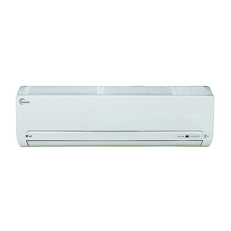
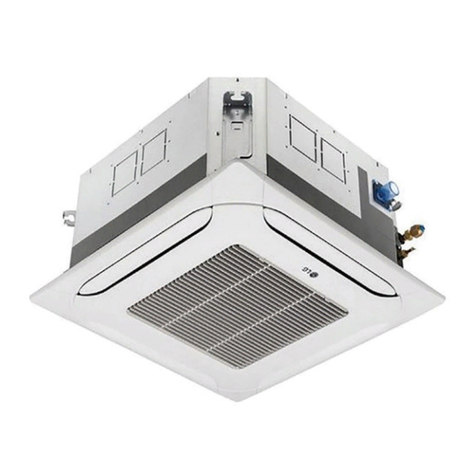
LG LT1030CR User manual

0
Please read the operating instructions ,and safety precautions carefully
and thoroughliy before [ns,taHin,g and op,erating your room air conditioner,
DEVENTANA
e
va/luable
may
proiper air
_pmper use,
order to p_vent
for any damages
|i_oner.

FOR YOUR RECORDS
Write the model and seria_ numbers here:
Model #
_tial #
You can fir_ them o,n a Ilabel _ the side of _ch un_.
Dealer's Name
Date Purchas_
II 8[ap[e you_ re_ipl[ to [his page #_#),e e_ar_t yc_ r_ it
to prove date of purchase or for warranty issue.
READ THIS MANUAL
In,side _,u wil! find many h_pful hints oin h_ to [Be and
maintain _ur air conditio,n_ pro_dy, ,,Justa little preventive
care on your _t can _ y_ a great: dea_ oi time and
money over the life of your air conditioner
YouH find many answers toi common p_oiblems in the c_rt
of t_¢_b_ho_ing tips. if _u revi_ our chart o_
Troubleshooting Tips first you may not _ to cal_ for
servia at a&
•Contact: the, author_d service t_hntctan for repair
or maintenance of this unit.
•Contact the installer for installation ,of this unit.
•The air conditioner is not lintendied for use by young
children or invalids without s,upervision_
,Young children should be _rvis_ to e_s,ure that
they _o not play with the air conditioner"
oWhen tlhe power cord is to be replaced, replacement
work shah be _rformed by authorized[ personnel only'
_si#g o_ly ,g_uine r_lacement p_rts,
•install_lon work musl be performed in _cor_#ce
w_th the National El_ri,o C_e [by qualified and
authorized personnel oniy_
2Room Air Conditioner

To prevent injury i to the user or other people and property damage, the fo_liowing instructions
_"°'"°'°'_"°.:c_'_o;_la,,oodoe,o,o ,os,,oc,,oo_,,,coosehormo_d o_heser,oosoeso
is classifi_ by the foJ]owJng indications,
I....m.moZh's..mO"od'c--e.theOoss'O'"o*deo*h:rse*'ou.'o.o1
[., CAUTION This symbo_ indicates the possibility/,of injury or dama_ to properties only J
i Meanings of symbols us_ in this manua_ are as, shown below,
B,esure, not to ,do,
Be sure to follow the instruction,
[] Installation,
*_her,_ise, it may cause a fire
or electrica_ sh_k, • Otherwi_, it may cau_ a fire
or eEectri_l shock, •It willl _u_ ellectric _ock or fire
due to heat generation
• It may _use failure and
ellectnc shock.
° Sharp _ges may cause
injury. • It may cau_ exp!osbn or fire,
Owner_ Manual 3

!I Operation
•There ='sdanger of fire or electric
shocL
• it may cau_ fire and electric
shocL
• It will cause electric shock or fire
due to heat _neration,
•It willcause failure of ma_ine or
ele_Eic sh_k_
• _iherwise, it may _use a fire
or electrica_ sh_k,
• The ap_arance of the air
cond_ioner may de'_edorate,
change color, or develop surfa_
f_aws._
• Otherwi_ it may cau_ fire and
el_tric shock a_i_nt.
° An oxygen shortage m_ occur,
• _henNi_, it m_ry e_ectrical
sho_ and failure.
° Since the fan rotates at high
_,_d daring operation, it may • Pr_ent accidenta! startJJpand
the,pei_bility Ofiniury.
4 Room Air Conditioner

SafetyPrecautions
• Hwill cause ebctric shock or fire • litwill cause elledric shock or fire. •It will _u_ electric chock.
due to heat generation_
• ff may cause etedric sh_ and
_mage
III In allatio, n
•Othe_ise, it:m_y cau_
explosion, and a fire,
• O_erwi_, it may cause dispute with the
neigh_rs.
* _ey are sharp and may cause
injury,
°O]he_ise, it may cause vibratio.n or water
[leakage.
Owner_ Manual 5

SafetyPrecautions
[] Operation
• it may cause inju_,.
• It may _use an injury through
dropping of the unit or fa!lling
dOWn.,
°'_tmay cause injury.
6Room Air Conditioner
,, it m_ cause produ_ failure.
* O_ration without riflers wiB
_use 'failure
° _her¢_ise, it may do harm to
your heaffh.
•The ap,pearan_ of Me air
conditioner m_ dieteriiorate,
change col.or,.ordevelop _rface
fl._s.
° it contains con_inmer4s and will
make you sick.
* Otherwise, it may cause
pe_ena_ injury.

Before Operation
1. Contact an installation specialist for installation.
2. Pllug in the power plug properlly.
3. Use a dedicat_ circuit.
4. Do not use an extension cord.
5. Do not start/stop operation by pluggin(}/unplugging the _wer cord.
6. if the _rd!plug is damaged, replace it with only an authorized replacement
part.
1i_ Being expos_ to direct airflow for an extend_ period of time could be
hazardous to your health, Do, not expose _cupants, pets, or plants to direct
airflow for extended periods of time.
2. Due to the _ssibilibj of oxygen deficiency, ventilate the r_m when used
together with stoves or other heating device&
3 Do not use this air conditioner for nonospecified special purples (e.g,
preserving precision devices, fo_, pets, plants, and art objects). Such u_ge
could damage the items,
1 Do not touch the metal _rts of the unit when removing the filter, Injuries can
occur when handling sharp metal edges.
2. Do not use water to clean inside the air conditioner. Exposure to water can
destroy the insulation, leading to possible electric shock.
3. When ,cleaning the unit, first make sure that the _wer and breaker are turn,_
off. The fan rotates at a very high speed during operation. There is a
_ssiibili#y of injury if the unit's power is a_identally triggered on while
cleaning inner parts of the unit,
For repair and maintenance, contact your authorized service dealer.
i!_ ii _i_
Owner_ Manual 7

Introduction
This symbol alerts you to the, risk of electric shock,.
This symbol alerts you to hazards that could cause harm to,
the air cond_ione, r.
This symbol indicates, sp_ial notes.
This, appliance _ouJd _ installed in accordance with the National Electdc Code,
THE SLEEVE AND THE REAR GRILLiE
(_ona_ly s_p_ied wi_tli_your unit}
SLEEVE ,ASSEMBLY
(l_c_uding Ah,_mi_umReal g_le)
REAR GRILLE
(Aluminum Rear grille)
THE UNIT
VERTICAL AIR DEFLECTOIR
AIR;FILTER
I_N_T GRILLE
(,Airin'take)
NORIZONTAL AIR DEFECTOR
(Ve_5ca_Louver}
VE N'rT OONTR@.....
A_RD_SCHARGE
C,AB_NET
_ONT GRILLE
8 Room Air Conditioner

EfectricalSafety
115V~ 230V~
t
Power cord may include a current:
in'te_upter device. A test and reset button is
provided on the plug case. The device,
should be tested on a periodic basis by first
pressing the TEST button and then the
RESF button,. If the TEST b_on does not
tnp or if the RESET button will not stay
engaged, discontinue use dthe air
conditioner and contact a qualified sewice
technician.
The shape may be different according to its.model
U_ W,aH Receptacle
Stan,_rd 125V, 3-wre groundiog
receptaclelat_ 15A,125VAC
Standard 2_V, 3°wire grounding
recep,tac_e ratad 15A, 250V AC
Standard 2_V, 3-wire grounding
r_eptacle rated _A, 250V AC
Power Supply
U_ 15 AMP. time
de_ay fu_ or 15 AMP
circuff: breaker.
U_, 20 AMP. time
de_ay fu_ or 20 AMP.
cimuit b_eaker
DO NOT USE AN EXTENSION CORD on 2_,
_8, and 230/_8 Volt un_s.
AI_wiring sho.uMbe ma_ in accordance with local
electrical c_es and reguiations.
Aluminum hou_ wiring m_t po_ sp_ial
problems, _nsu_ a qualffi_ electrician,
,A WARNING
Never push the _e_ button during
_hetwise this plug can damage°,
Th_ device c_tains chemiicaL including
lea& known toithe State of Cafi_omia to
_u_ ca_er, and birth d_ecte o,r ofhe_
r_roductJve harm.
Wash hands afler handli_i.
Do not remorse, modify _ immerse this plug.
If th_ ,de_ice trit:_, the cau!_ it to be
oorrected _fore fu_her use.
CAUTION
The conductors iinsiide _is cord are
surrounded by shields, which monitor
leakage current,
These shields a_e not g_ound_
Pedodbalily examine the cord for any
damage, Do not u_ this product in the
event the shields become expose.
Avoid sh_k hazard, this unit can not
user seirvic_ opening the tamer
resistant. Sealed portion dthe unit
voids all warranties and performance
c_aims This unit not intended for use
as an on-off switch.
Owner_ Manual 9

(PLEASE READ CAREFULLY)'
FOR THE USER'S PERSONAL SAFETY; THIS
APPLIANCE MUST BE PROPERLY GROUNDED
The _ver cord _ this a#p]ian_ is _uip_d with a
three-prowl (grinding) I_ug. Use this:with a standardi
thr_s]ot (grinding) waB _er o,uUet to minimize the
hazard of e_tdc shock_ "'[he c_tomer sho,u_d have
the wall rece_acle ar_ circu_ ch_k_ by a qualified
e]e_ician to make sure the receptacle is propedy
DO NOT CUT' OR REMOVE THE THIRD (GROUND)
PRONG FROM THE POWER PLUG,
A. SITUATIONS WHEN THE APPLIANCE WILL BE,
DISCONNECTED OCCAS|ONALLY:
Because o! potent_] _fel:y hazards, we stK)ngly
dliscou!r_ge the use of _ adapter plug. However, if you
wish to use an ada_er, a TEMPORARY
CONNECTIiONi may be made Use UL4isted adapter,
available from most 1o_ har_are stores°
The la{ge st_: in tl"_ a.da.pler must _ a[ign_ with the
_arge silo| in the roce_ac_e _oiassure a proper polarity
connection.
ACAUTION
: At_chinojtheadapter glroundterminalto the wa_l
r_pt_e _s_ew do_ not groundthe
app|_nce unless the coverscrewis n'_tal,and not
insu_t_ and thewa_lte_ptacle is grounded
throughthe ho,u_ widng,_e custommshoe_i
h_e the circuitchoked bya qualifiedelectti_an to
_ke sere_e recep_:_e _properlygro_nde&
Di_s_necl the _wer cord ff_n the ada_er, using
one hand on each_ Othe_ise the adapter ground
t_mi_l might break. D,O NOT USE the app{ia_e wi_lh
a br_en ada_er plug,
B. SITUATIONS WHENTHE APPLIANC_ WILL BE.
DISCONNECTED OIFTEN,
Do not use an adalpte[ plug in these s_uations
Unplugging t_ p_er cord frequently can lea(] to an
eventu_ breakage of the ground terminal, The wall
p_ outl_ sh_4ld _ replac_ by a three*skit
(grinding), _tlet instea&
USE OF EXTENSION CORDS
Because of potentAI _fety Ihazardls, we strongly
discourage the u_ of an extension co_d_H,cTwever,if
y_ wish to use an extension _rd, use a CSA
certJfiediULoiisted 3owire (grounding) ext_sion cord,
rated at 15A, t25V.
10 Ro,om, Air Co,nditioner

Ins_llation
Remo'_ packir_ mate,rials from De wall s_eeveand tape
from t_ air conditio_r
INSTALLATION REQUlREMENiTS
If you use an existing wall sl_ve, you _ould
measure its dimensions,
install the new air conditioner according to the_
instaBation instruc4:k3nsto achieve De best
performan_, All wal! sleeves u_d to mount the new
air condi_oner mast _ in go_ s_uctura_ _ndition
and have a rear grille to _curely attach the new air
conditioner. (FIG. 1!)
With the LGE s,l,eev_optionally supplied with
y_r unit), you can maintain the best pedorrr_nce o1
the new air conditioner, (FiG 2:)
(511 mm)
AIr Condif_e,ner FIG 1
INS,TALLATION HARDWARE
2 Size options,
®N_I= OF PARTS
PLASTIC GRILLE
VERTICAL _NSU_TION STRIP
AROUND INSULATION STR_PS
@ BAFFLE i
TRIM FRAME
SHIM
P_STIC NUTS AND WASHER SCREWS
Q'TY
1
1
2
(¢56 ram)
LGE Wall Sleeve F_G.2
ELECTRICAL SERVICE
Check your avaiilaMe e_e_ri_t eerv_e_ The _ower
supply available must _ the same as tha_ shown on
the unit nameplate (found on le_: side of cabinet).
All mode_s are equipped with a 3-p_ong _rvice plug
to provi® proper servi_ and _fe positi_
grounding. Do not change plug in any w_/. Do not
use inn adapter pfugo I1your present wall outer do,_
not: match you_ plug, call a qualified electrician to,
make lhe necessary corrections. ,SAVE CARTON fer
stora_ and this OWNER'S MANUAL for future
reference, The carton is the best way to store unit
during winter o,r when not: in u:_.
To a_id risk of personal injury, property
damage, or product dam_e due to the weight of
this device and slha_ _ges th_ may
° Air ce_iflo_,m covered in this manual posean
excessive ,_igN hazard.Two,or more peop_ are
n_ed tot_ve and installtl"_ uni_.
To preve_ injury'or strain, use proper lilting and
carryi_i techniques w_n _ving unit,
• Carefully inspe_ location w_re air conditbner will
be inst_l_l. _ sure itwill su_rt _e we_ht of
the unit overan extended period of time,
iI Hand_ air conditbner with care.Wear protective
t_loveswhoever lifting or carrying tlr_ unit.AVOID
e s_rp metal fl_ of front and rear ceils.,
° Make sure air conditioner does netAll dun_
in_alb_en.
IREQUIR ED TOOLS:
•Tight Fittinggloves
•Slendard sc_'dri'ver
• Phillips screwdriver
•Pliers
° Sharp knit,
•,3/8cinch o_n end
wrench or adjustab4e
wrench
• t/4o,inch hex _cket
and ratchet
_i Tape _asure
•,E_tric dd_l
• 1/4-inch drill bit
Owner_ Manual 11

Installation
INSTALLATION
CAUTION
We strongly recommend the removal of the
old wall sleeve and the installation of a new
LGE Wall Sleeve.
If you decide to keep the existing wall sleeve,
you have to redirect the louvers at the back of
the wall sleeve illustration. The use of pliers is
recommended. If you DO NOT redirect, you
run the risk of poor performance or product
failure. This is not covered under the terms of
the LGE warranty.
* Pick a location which will allow the conditioned air
to blow into the area you want. Good installation
with special attention to the proper position of the
unit will lessen the chance that service will be
needed.
ITEMS IN INSTALLATION HARDWARE
You may not need all parts in the kit. Discard unused
)arts
ITEM (inches)
Plastic grille
Vertical insulation strip
Around Insulation Strips
Horizontal Insulation Strip
Support Block
Baffle
Shim
Trim Frame
Washer Screw
Nuts(Plastic)
Grille Rear
263/4 x 161/2
159/16x 13/8x 13/8
671/8 x 13/8 x 25/32
5927/32 x 13/8x 13j_
237/32x 1318x 13/lc
13/4 X 13/8 X45/16
14 x 41/2x 1/8
1113/16X 1 X3/4
Qty.
1
1
1
1
1
2
1
2
2
4
4
1
HOW TO INSTALL
D dentify the existing wall sleeve before installing
the unit from the listed below.
Brand
White-Westinghouse
Frigidaire
Carrier (52F series)
General Electric
/Hotpoint
Wall Sleeve Dimensions (inches)
Width Height
25-1/2 15-1/4
26 15-5/8
Whirlpool 25-7/8 16-1/2
Fedders/Emerson 27 16-3/4
LGE 25-7/8 15-17/32
Emerson/Fedders 26-3/4 15-3/4
Carrier (51S Series) 25-3/4 16-7/8
Friedrich 27 16-3/4
Depth
16, 17-1/2
or 22
16-7/8
17-1/8
or 23
16-3/4
or 19-3/4
16-23/32
15
18-5/8
16-3/4
All wall sleeves used to mount the new Air
Conditioner must be in sound structural condition
and have a rear grille that securely attaches to
sleeve, or rear flange that serves as a stop for the
Air Conditioner.
H
El
El
Remove old air conditioner from existing wall
sleeve.
Clean the interior of an existing sleeve.
(Do not disturb seals.)
Wall sleeve must be securely fastened in wall
before installing the air conditioner. Use the
nails or screws through sleeve into wall, if
needed. Repaint sleeve if needed.
Prepare the wall sleeve for installation of the
unit. If you plan to use your existing wall sleeve,
and it is not LGE, use procedure B or C below.
Procedure
A
B
C
Brand
LGE
White-Westinghouse
Frigidaire Carrier
(52F series)
General Electric
/Hotpoint
Whirlpool
Carrier (51S series)
Fedders/Emerson
Emerson/Fedders
Friedrich
Depth(inches)
16-23/32
16, 17-1/2
or 22
16-7/8
17-1/8 or 23
18-5/8
16-3/4
or 19-3/4
15
16-3/4
_ Install new unit into wall sleeve.
CAUTION
When installation is completed, replacement unit
MUST have a rearward slope as shown. To
achieve 1/4" slope, remove the backing from the
11-13/16" shim strips and attach them as shown
below in Fig. 3. Place the higher portion of shim to
the front of the rib on base of wall sleeve.
1" high]'[--
SHIM PLACEMENT
lI 3/4" High
UNIT Walt Sleeve
UNIT INSTALLATION
FIG. 3
12 Room Air Conditioner

Ins_llation
PROCEDURE A
HH yOU are using the new sleeve (optioina]l[y
s.upp_ied with your unit),skip to step 3..
O,#ie_ise, install the phstic grilJ,e_rom the kit
Cut the plastic grille to 25o1/Z wide and t 5i-
1/4" high, P_a_ the phstic grillle to the inside
of the walll s_eeve at the rear flange°
_ hstalf the new unit into the wa_J_eeve_
lb, .as_mb_e trim, snap the tab of each pie_
into the _ot of the other pike as sh_n be_,
SNe trim over the front ot the air co,nditio,ner
anti[ trim isflush w_h _eeve as shown _[ow_
FiG. 4,
_ asten the 4 washer _rews to secure the g[i_le
to the wall _eeve,, If you need p_stic nuts to,
mount plastic grille to the insi_ of the wa_l
s_eeve, hero are phsfic nuts in the instalhtbn
kit. The nuts ae installed 'f_o,mthe inside of the
slleeve and are pressing into the _uare holes
of the _ear flanges.
_ Rem_,e the
; backing from the Vertical insuhtion
strip, 15,_/_6x 1s_8x i3,,8 and attach that to the
inside right of the s[_,/e as shown below..
Remove the backing from the Around hsuhtion
strip, 67_,,'8x lS_ x 2_','s=and attach that t:o the
inside front ot Me _ee'_ as _own _low:
_or Ould_r
F]Go 6
T_iim(2 ea)
Wail
FIG. I
&CAUTION
•Air cond_ionersco_r_ inthis manualpo_ tan
excesses weighthazard_T_ or morepeopieare
_,eded to moveand installthe unit,
To preJentiniuryor str_n, use properlifti% and
carryingtechniqueswhenmovingun_,
•W/_n handlingthe _r conditioner,be carefu_to
avod cutsfrom sharp me_ fins on front and rear'
coi_so
• Makesure air®nditioner doesnotfall duri_g
#emoval,
° Ifunit doesnotoperae after inaalllationche& to
surethe circuiti_errupter has notbeentrip_d,
Referto't_ Troubleshooti_ guide for resel
Owner_ Manual 13

Installation
PROCEDURE B
_edirect the lieuvers ai Me back oll the wall
sleeve to 60P angle as shown in 'the FiG 8, The
use o! piiers is _ec4_mmended,
RearLouvers
(Top View)
HG..8
lf the wall sleeve already has a rear gdBe, skip
to step 4. If the wall slieeve dees not have a rear
gHBe or leuvered panel install the ptastic grille
f[o,m the kit. ,Cut the plastic _i]le to 25ol/2 '' wide
and ! 5ol/4 `°high. Place the plastic grille to the
inside of the waB sl,e_ at the roar flank.
DRemove the b_cking from tlhe Vertical Insulation
strip 159_ x lS,_'8x 1% and attach that to the
inside right of the sleeve as shown below
Remove the backing from the Around hsulation
strip 67% x 1% x 2%2 and attach that to the
inside front ,o_the slee*#e as;shown below.
l;nd_ Outdoor
I1
FIG. 1t
Pla_ the plastic grille FIG,9
_ asten the 4 washer sct_s to s_ure tlhe griBe
to the wall s_eeve° If you need plastic nuts to
mount plastic grille to _e inside of the wall
sleeve, there are plastic nuts. in the ins_llatio, n
kff:.]"he nuts are instaH_J from the in,de of the
sleeve and arre pressed into the s4uare holes o_
the rear flange.
Fasten the screws FIiG. 10
Dif the depth ol your existing wall s4ee.v_ is. less
than or equal to ! 8,'°,skip, to step 60the_i_,
cut the ba!fles and the support b_oc_ according
to len_h "W' in _e table below,
wa_lsle,_e (inches}
18% <D_19 _/,
19_/, <D _ 22
Length"A"
4
14 Room, Air Conditioner

PROCEDURE B
Insta!lation
as _m FiG 13. Slide the baffle into_ots o4
the supp,oMMocks
Wall
Wall-
Sleeve
U install the new" unit into the wall sle_e.
_ _mble trim as de_db_ in Step 5,
IProc_ure A,
FIG 13
. Air _nditioners cover_ in this manual_ an
excessive_ight hazard,Twoor morepeopleare
need_ to mo_ and install_e unit,.
Topreventiniuryor stra_in,useproper lifti% and
carryingtechniqueswhenrno_ng unit.
coils
° Makesureair cond_ionerdoesnol _al_du_ing
removai,
° If unit _es notoperateafterinaallation check,to be
sure 1hecircuitil_er_upterhasnot beentrip_d,
Referto theTroubleshootingguidefor reset
procedure.
Ownerb Manual 15

Installation
PROCEDURE C
_ edirect the. Iieu_re at the back ot the web
sleeve to 60 _'angle as s,hewn in the FiG 14
The u_ of pBers is r_ommended_
"t:32
Rea; Louvers
(Top View}
FIG, 14
]f the wallll sl_e already has a rear gdlle, skip
to step 4. it the wallll slieeJe does not have a rear
g_iBe or ]ouvered panel instet] the p]astic grBfe
f_o,mthe kiL Cat the plastic g[ile to 26.°1/2 'wide
and ! 5o!!2 'high Piece the plasti,c grille ilo the
inside of the waB sJeeve at the rear flank.
Place, the p_aetic grille FiG. 15
_ aste,n the, 4 washer :scr_s to s_ure, the gfiBe
to the web slle@Je, if you need plastic nuts to
mount plast:ic grille to the inside of the web
ele_we_ there are pllastic nL_tS,in the installation
kiL The nuts are inste][_ from the in,de of the
sleeve and are pressed into the _uare holes of
the rear flarnges°
Fasten the _rews FIG_ t 6
Remove the backing from tlhe Horizontal
Ens,u]atioinstrip 237,_ × 13_sx !_ and attach
that to the inside right o1'the s_eve as shown
_low: Remove the be_ing from '[he Around
_nS;U_:_Oi[_ strip 5927G_ × 1% × 1% and erich
that to the insi_ front o{ the s]e_e as shown
below:
Indoor Out.or q
8v__
F_G. 17
if the depth of you_ existing sle_e is less than
or equal to 18_',s_p to step 7. OthePwi_, cut
|he baftl_ and the suppor[ M_ks according to
Len_h 'W' in the table _]ow.
Len_h "A_
(inches)
18 <D _<18_% 3/4
_ emo_ the ba_ing 'from the sup_rt bf_k:s
and e'_ach them to the in,de of the wall slee,,e
as shown FIG 19. Slide the baffle into slots of
the _Jppoir_ Necks
W,a_
Wall .......
S_ee¢,e
F'_G.19
16 Ro,om, Air Co,nditioner

PROCEDURE C
W
tns_llation
To achieve, rearward elo_ |or unit draining,
remove the _cking from 11he11_3a_"shim
strips and at_ch them as shown below in Fig,
21. The higher portion of _im is,to, be p!aced
in front of Me, rib, on the base of wall s_e_¢e°
ACAUTION
• Air conditionerscoveredin this mian_al_se an
,excessiveweighthazard,Two,ormorepeopleare
need_ t,omoveand instali_e unit
TopreJ_ntinjuryor strain,useproper liftingand
carying techniqueswhen mo_ng unit.
• Whenha_ling theair conditioner,be carefu!to avoid
,cutsfrom sharp metalfins on frontand #earcoils,
• Makesureair cond_io_r does _t falidudng
removal,
• If unit_es notoperatea_terinstallationcheck,to be
F::_G,,21
Unetall the n_ unit into the w,all sleeve
_ ssemble #ira as (_scribed in Step 6,
Pro,c_u_ Ao
Owner_ Manual 17

OperatingInstructions
'_ne controls ,will l_k like one of the _llowing,
,-FAN SPEED
*Eve_ 'timeyou push this b,u_on,itadvanc_ the _ng asto,llows:{High_ Low-_M_ -* High}
REMOTE CONTROL SIGNAL
TEMPERATURE S_ING
, Use this buttonto automatically c_->ntrolthe
temperature of the room,
The tem_'ature _n be _ within a range of
@_"Fto 8_'F by i_rements of I_'F
•The settir_ appears in #le display,
POWER
*To turn _e air conditioner ON, push_iebu_en,
Toturn the air ce_tioner OFF push the bu_on
Thisbu_ontakesprior_ over_qyotherbL_on
. Whenyoufirst:turn_on.theunit:isincool
mode,Highfans_ed, Tempe_tu_ se_ingat
72°F.
oSTART TIME:
,Ifunit:is off use l'imer to set:number db<sursbefore unit sta£s.
• Push Timer hubertto advance _ng fpam1Hour 2Hours .........,
---_12Hou_ m_imum
'--MODE
- Pushthis button to shi_ me® of operation from COOL -* ENERGYSAVER -_ FAN,
oCOOL:
•Fan _uns continualily to_ norma_ _oling o_ation
ENERGY SAVER:
,.Thefan sto_ wb_n tl_ compressor sto_ ___ling Approximately ,_vory3 min_os 'tt_ 'ranw#l _m on _d _e uni_.will
ctr_cktt_ roomair temperature to determine _tcooli% is ne_ed
oFAN:
• Fan-only ope[ation,.
after an electrical power failure, the unit will begin to ,run,at its last setting,
18 Ro,_m, Ah Co#ditioner

OperatingInstructions
Theremotecontrol and control panel will look like one of the following pi_ures.
• To turn the air _nditbner O,N,p_h this bu_on.
To turn t_ air conditioner OFF, p_h t_ button again.
•This bu_on takes p,dod'_ over any ot_,r bi_on.
,.When you first turn it on, the unit is in c_.ol m<_ie_High fan spe_,
Temperature setting at 72_'F.
,.Auto Resta_
In the event at a power failure, the unit wilUrun _ t_ p_ov_oi_ se_ing once
p,o_er returns.
TEMPERATURE SE_NG
•Use this bu_on |o autematk,alliy_'_nholthe tempe_ture o_the morn
Thetemperature canbe set within a ra_ of'60_Fto 8_F by
increments of I_F.
• The setting _2eas in the display.
FAN SPEED
,.Every time you pushthis b_on it a@ances,the se_r'_ as fo,llo_:
(Higho-_Low--_Med-_High)
TIMER
-SHUT-OFF TIME
•You wiBusu_lyu_ shut-offtimewhileyous_p.
• If unit is.running, useTimer toJset nurr_e.rof hoursuntil shutoff.
• Foryour sleepir@_m_oA, once Time isseL tP_Temperaturesetting will
rai_ 2"F are[ 3:0rain, and once again after a_ther 30 rain
• P_h Timer button to advanc_ settingfrom 1Hour.-, 2Hours ....._.
12Hoursmaximum.
.°STARTTIME:
,If unff is off, u_ Timer toset of _'#ursbefore units_rts,.
• PushTimer b_on to a_J_ce selli_ from lt4oui[ -_2Hours -_ .. -_
!2Hours maximum.
- P_h th_ butter to ehi_ m_ of _ration froim COOL ....ENERGY SAVER -_ FAN.
oC_L:
• Fan runs con_n_By for normal ,cooling o[_ration.
- ENERGY SAVER:
• T_ fan stops wlhen the ®rr#res_r stops cooling. Approximately evePj 3 minutes the fan wiBturn en
and t_ unit wi[_ cff_lk the room air temperature to determine if cooling is ne_d_
FAN:
• Fan-enly _,eratJen.
Owner_ Manual 19

Operating Instructions
i i
! Remove the cover from the back of the remote
controller
2. !nsert two bakeries.
•Be _re that the (+) and (-) directions are
c,o_ect.
• Be _re that bio,thbia_eries are new.
3. Re-attach the cover.
• Do not u_ rech,ar_able b_tedes,
Such batteries differ from _andard
dry ,cells in _ape, dimensions, and
_rformance.
° Remove _e ba_er_s from _e
remote controffer if the air
_nditio.ner is not wing to be used
1oran extended len_h of time,
The ventilation lever is _ocat_ in _e right ,ofthe air di_harg_,
The ventilation lever must be in the CLOSE p,osPd.onin order to
maintain the best cooling conditions.
When fresh .airis necessary in the r_m, set the ventilation !ever to
the OPEN position
The damper is opened and room air is exhausted outside. I
PULLOPEN/PUSHCLUE
T_ dim_ion of air can be _n_roille,dwherever you want _ adiusting t_ horizon_l louver.andthe ve_aJ louver.
•HORIZONTAL AIR-DIRECTION •VERTICAL ,AIR'-DIREC_ON CONTROL
The horizontal air direction isadjusted by moving
vertical louver.
The lever of vertica! _ouveris I_ated in the right and
left side of the ,airdischa#ge.
The vertical air direction is adjusted by moving the
horizonta_ louver.
20 Room, Air Conditioner
Other manuals for LT1030CR
1
Table of contents
Other LG Air Conditioner manuals

LG
LG LW8000PR User manual

LG
LG APNQ55GT3E0 User manual

LG
LG ARNU18GV1A4 User manual

LG
LG LW1812HR User manual

LG
LG V-NET PDRYCB100 User manual

LG
LG HSN12IPX User manual

LG
LG Multi V ARNU093TUD4 Installation and operation manual

LG
LG ARNU153BGA2 User manual

LG
LG LSN3VP5D User manual

LG
LG BWC186MBAB0 User manual
Popular Air Conditioner manuals by other brands

Rohnson
Rohnson R-894 user manual

Panasonic
Panasonic CS-KS18NB4UW & CZ-18BT1U + CU-KS18NKU manual

Mitsubishi Electric
Mitsubishi Electric Mr. SLIM PKA-M-LAL Series installation manual

Mitsubishi Electric
Mitsubishi Electric MSZ-SF25VE Service manual

dirna Bergstrom
dirna Bergstrom bycool green Series Troubleshooting

Frico
Frico AD100 Original instructions