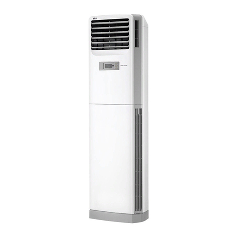
LG THERMA V User manual

www.lg.com
P/NO : MFL69676301
Please read this manual carefully before operating
your set and retain it for future reference.
(Air-to-Water Heat Pump)
Original instruction
OWNER’S MANUAL
AIR
CONDITIONER
ENGLISH ITALIANO

2Air-to-Water Heat Pump
Air-to-Water Heat Pump Owner’s Manual
TABLE OF CONTENTS
FOR YOUR RECORDS
Write the model and serial numbers here:
Model #
Serial #
You can find them on a label on the side of each
unit.
Installer's Name
Purchased Date
n
Staple your receipt to this page in the event you
need it to prove date of purchase or for warranty
issues.
READ THIS MANUAL
Inside you will find many helpful hints on how to use and
maintain your AWHP properly. Just a little preventive
care on your part can save you a great deal of time and
money over the life of your product.
You'll find many answers to common problems in the
chart of troubleshooting tips. If you review our chart of
Troubleshooting Tips first, you may not need to call for
service at all.
PRECAUTION
•Contact the authorized service technician for repair or
maintenance of this unit.
• Contact the installer for installation of this unit.
• AWHP is not intended for use by young children or
invalids without supervision.
• Young children should be supervised to ensure that
they do not play with AWHP.
• When the power cable is to be replaced, replacement
work shall be performed by authorized personnel only
using only genuine replacement parts.
• Installation work must be performed in accordance
with the National Electric Code by qualified and
authorized personnel only.
Instructions for the use of
owner’s manual ...........................6
TERMOTRONIC™ controllers.....8
Quick settings............................14
Advanced settings.....................26
User menus and parameters ....45
Information display of operation
.....................................................52
Disruptions in operation, alarms
and troubleshooting..................56
Maintenance and Service..........61
Settings of your heating system
at start-up ...................................62

Owner’s Manual 3
Safety Precautions
Safety Precautions
To prevent injury to the user or other people and property damage, the following instructions must be followed.
nIncorrect operation due to ignoring instruction will cause harm or damage. The seriousness is classified by
the following indications.
WARNING
CAUTION
This symbol indicates the possibility of death or serious injury.
This symbol indicates the possibility of injury or damage.
WARNING
Always ground the product.
• There is a risk of electric shock.
Do not use a defective or underrated cir-
cuit breaker. Use the correctly rated
breaker and fuse.
• There is risk of fire or electric shock .
Do not use a multi outlet. Always use
this appliance on a dedicated circuit and
breaker.
• There is risk of fire or electric shock.
For electrical work, contact the dealer, seller,
a qualified electrician, or an Authorized
Service Center. Do not disassemble or repair
the product by yourself.
• There is risk of fire or electric shock.
Always ground the product as per the
wiring diagram. Do not connect the
ground wire to gas or water pipes light-
ening rod or telephone ground wire.
• There is risk of fire or electric shock.
Install the panel and the cover of control
box securely.
• There is risk of fire or electric shock due to
dust , water etc.
Use the correctly rated breaker or fuse.
• There is risk of fire or electric shock.
Do not modify or extend the power
cable. If the power cable or cord has
scratches or skin peeled off or deterio-
rated then it must be replaced.
• There is risk of fire or electric shock.
For installation, removal or reinstall ,
always contact the dealer or an Author-
ized Service Center.
• There is risk of fire, electric shock, explosion,
or injury.
Do not install the product on a defective
installation stand. Be sure that the installa-
tion area does not deteriorate with age.
• It may cause product to fall.
Never install the unit on a moving base
or a place from where it can fall down.
• The falling unit can cause damage or injury
or even death of a person.
When the product is soaked (flooded or
submerged) in water , contact an Author-
ized Service Center for repair before
using it again.
• There is risk of fire or electric shock.
Be sure to check the refrigerant to
be used. Please read the label on the
product.
• Incorrect refrigerant can prevent the normal
operation of the unit.
Do not touch , operate, or repair
the product with wet hands.
• There is risk of electric shock or fire.
Do not place a heater or other heating
appliances near the power cable.
• There is risk of fire and electric shock.
ENGLISH

4Air-to-Water Heat Pump
Safety Precautions
Safely dispose off the packing materials. Like
screws, nails, batteries, broken things etc after
installation or service and then tear away and
throw away the plastic packaging bags.
• Children may play with them and cause
injury.
Make sure to check that the power
device is not dirty, loose or broken and
then turn on the power.
• Dirty, loose or broken power device can
cause electric shock or fire.
In unit the step-up capacitor supplies
high voltage electricity to the electrical
components. Be sure to discharge the
capacitor completely before conducting
the repair work.
• An charged capacitor can cause electrical
shock.
Do not open the front cover or grille of the
product during operation. (Do not touch the
electrostatic filter, if the unit is so equipped.)
• There is risk of physical injury, electric shock,
or product failure.
If strange sounds, smell or smoke comes
from product, immediately turn the breaker
off or disconnect the power supply cable.
• There is risk of electric shock or fire.
Ventilate the product room from time to
time when operating it together with a
stove, or heating element etc.
• Oxygen deficiency can occur and hence
harm your health.
Turn the main power off when cleaning
or repairing the product.
• There is risk of electric shock.
Take care to ensure that nobody espe-
cially kids could step on or fall onto the
unit.
• This could result in personal injury and prod-
uct damage.
Take care to ensure that power cable
could not be pulled out or damaged dur-
ing operation.
• Almost the antifreeze is a toxic product.
Do not touch any electric part with wet
hands. you should be cut power before
touching electric part.
• There is risk of electric shock or fire.
Do not touch refrigerant pipe and water
pipe or any internal parts while the unit
is operating or immediately after opera-
tion.
• There is risk of burns or frostbite, personal
injury.
If you touch the pipe or internal parts,
you should be wear protection or wait
time to return to normal temperature.
• Otherwise , it may cause burns or frostbite,
personal injury.
Do not touch leaked refrigerant directly.
• There is risk of frostbite.
Make sure to install mixing valve (field
supply). The mixing valve is setting the
water temperature. The hot water temper-
ature maximum values shall be selected
according to the applicable legislation.
Do not heated to a temperature of
more than provided by the product.
• Otherwise, it may cause fire or dam-
age of product.
When installing the unit, use the installa-
tion kit provided with the product.
• Otherwise the unit may fall and cause severe
injury.
Be sure to use only those parts which
are listed in the service parts list. Never
attempt to modify the equipment.
•
The use of inappropriate parts can cause an elec-
trical shock, excessive heat generation or fire.
Do not use the product in a tightly
closed space for a long time. Perform
ventilation regularly.
• Oxygen deficiency could occur and hence
harm your health.
Do not allow water to run into electric
parts. Install the unit away from water
sources.
• There is risk of fire, failure of the product, or
electric shock.
Do not store or use or even allow flam-
mable gas or combustibles near the
product.
• There is risk of fire.
Wiring connections must be secured
tightly and the cable should be routed
properly so that there is no force pulling
the cable from the connection terminals.
• Improper or loose connections can cause
heat generation or fire.

Owner’s Manual 5
Safety Precautions
CAUTION
Do not install the product where it will be
exposed to sea wind (salt spray) directly.
• It may cause corrosion on the product.
Keep level even when installing the
product.
• To avoid vibration or noise.
Do not install the product where the noise
or hot air from the unit could damage or
disturb the neighborhoods.
• It may cause a problem for your neighbors
and hence dispute.
Always check for gas (refrigerant) leak-
age after installation or repair of prod-
uct.
• Low refrigerant levels may cause failure of
product.
Do not use the product for special pur-
poses, such as preserving foods, works
of art, etc. It is a consumer AWHP, not a
precision refrigeration system.
• There is risk of damage or loss of property.
Do not block the inlet or outlet of air
flow.
• It may cause product failure.
Use a soft cloth to clean. Do not use
harsh detergents, solvents or splashing
water etc .
• There is risk of fire, electric shock, or dam-
age to the plastic parts of the product.
Do not step on or put anyting on the
product.
•
There is risk of personal injury and failure of prod-
uct.
Do not insert hands or other objects
through the air inlet or outlet while the
product is operating.
• There are sharp and moving parts that could
cause personal injury.
Be cautious when unpacking and
installing the product.
• Sharp edges could cause injury.
If the refrigerant gas leaks during the
repair, do not touch the leakaing refriger-
ant gas.
• The refrigernat gas can cause frostbite (cold
burn).
Do not tilt the unit when removing or
uninstalling it.
• The condensed water inside can spill .
Do not mix air or gas other than the
specified refrigerant used in the system .
• If air enters the refrigerant system, an exces-
sively high pressure results, causing equip-
ment damage or injury.
If the refrigerant gas leaks during the
installation, ventilate the area immediately.
• Otherwise it can be harmfull for your health.
Dismantling the unit, treatment of the
refrigerant oil and eventual parts should
be done in accordance with local and
national standards.
Do not expose your skin or kids or
plants to the cool or hot air draft.
• This could harm to your health.
Use a firm stool or ladder when cleaning,
maintaining or repairing the product at
an height.
• Be careful and avoid personal injury.
The hot water may not be available imme-
diately, during disinfection operation or
depending on the amount of hot water.
During floor heating operation it is
important to limit the minimum/maxi-
mum water temperature.
ENGLISH

Instructions for the use of the documentation
6Air-to-Water Heat Pump
Instructions for the use of owner’s manual
Before first use, read owner’s manual thoroughly and learn its content. You will learn the purpose,
functions and the handling procedures for the device.
In case of malfunctions of the heating system first consult Section(Disruptions in operation, alarms
and troubleshooting) and consult your installer who will find the reason for the malfunction and
resolve it. In case the malfunction cannot be resolved, he will contact the customer service of the
manufacturer who will resolve the malfunction.
Important information
The instructions are written to give you information on all the needed activities before the first and
further use. The manual describes the process of setting up and use of the device.
Incorrectly set parameters of the control unit can lead to stoppage or incorrect operation of the
device. To reduce risk the manual points out important information with the use of symbols. Follow all
general safety instructions and warnings connected with the operation.
NOTE
In case the product shall be given to a third person for use, the manual has to be handed over to
them as well.

Instructions for the use of the documentation
Owner’s Manual 7
ENGLISH
Glossary of used terms and conceptions
In case of unfamiliar terms in the document you can find the explanation here.
- ALTERNATIVE SOURCE: The heat source is used for systems with solar collectors, masonry
heaters and wood stoves when we either do not have a heat source on hand at any moment or an
automatic switch through the signal from the controller of the device (i.e. in a wood stove) is not
possible.
- AUXILIARY EXTERNAL SOURCE: The heat source found alongside the device (i.e. oil/gas/pellet/
external heater furnace) and can be used either alongside the device alternatively (the either-or sys-
tem) - automatic switch through the signal from the controller of the device. In case of a device mal-
function (in the so-called anti-freeze programme) the alternative source can take over the task of
heating for a short time.
- SPARE SORCE or Backup source: The flow heater which is installed in the device and turns on in
the case of device malfunction (in the so-called antifreeze programme). This ensures temporary
operation for bridging the time until an authorized person from the service company arrives and cor-
rects the error. The spare or additional source can be used as “assistance” to the device under the
so-called bivalent point when the capacity of the device does not cover the losses of the building.
- HEATING WATER: The liquid which flows inside the heating system (pipelines, floor, wall and radia-
tor heating).
- DHW: The water intended for sanitary use (cleaning, showering, washing ...).
- HEAT PUMP (HP): The device which takes energy from the environment and supplied mechanical
work and adds warmth to heating and DHW. In the text below the term ‘device’ will be used for the
heat pump.
- HW: The device takes heat from the earth.
- AW: The device takes heat from the air.
- WW: The device takes heat from groundwater.
- Parameter NORMAL: The desired temperature of heating in the Normal mode of operation.
- Parameter ECO: Lowering the desired temperature in the Eco mode of operation.
- Parameter COMFORT: Raising the desired temperature in the Comfort mode of operation.

TERMOTRONIC™ controllers
8Air-to-Water Heat Pump
Controlling the device and heating system
The device and heating system can be controlled with the use of 4 buttons on the controller interface
TERMOTRONICTM. The controller interface has a 4-line LCD screen which displays the current
state of the device or controller and a LCD light indicator of malfunctions in the operation of the
device (ALARM).
The controller interface TERMOTRONICTM in devices:
BUTTON BUTTON FUNCTION
MENU: Scrolling through the main menu and sub-menus.
ENTER: On, off, accessing the menu, accessing the settings and confirm-
ing selected values.
»+«: Selecting the values, scrolling up the menus and sub-menus.
»-«: Selecting the values, scrolling down the menus and sub-menus.
ALARM: Indicator of device malfunction.
General
TERMOTRONIC™ is a self-adapting controller for controlling the heat pump (hereinafter the
DEVICE) and the heating system. It controls the operation of the device so as to ensure the most effi-
cient way to produce the desired temperature of the building based on the needs of the heating sys-
tem and outside temperature.
The TERMOTRONIC™ controller offers controlling of the device and the heating system of the build-
ing (no more than 4 heating circuits) as well as controlling the heating with an alternative heat
source, active cooling with the device, heating DHW with the device and/or alternative heat source
and/or backup source.
TERMOTRONIC™ controllers

TERMOTRONIC™ controllers
Owner’s Manual 9
ENGLISH
Standby................................
Heating 35.5°C
Return 35.3°C
DHW 49.0°C
Operation of the device
After the start-up delay time the device starts operating in the selected mode (heating, cooling or
heating DHW) according to present needs. The display displays the status:
In the case the set temperature parameters (Heating, Return, DHW ...) is reached, the device dis-
plays Standby.
Heating................................
Heating► 35.5°C
Return 35.5°C
DHW 49.0°C
NOTE
- The temperature values can differ from the ones displayed on the picture.
This also applies for all following pictures.
- If before shut down the device was in a state of HP STOP (HP STOP), it returns to the HP STOP
mode after switching on the main switch or installation breakers. The display displays HP STOP.
The device is turned on by holding the (ENTER) key for 3 seconds - see below for more
information.
NOTE
Depending on the type of device the delay lasts from 30 to 300 seconds.
Activating the device
After switching on the main switch or installation breaker the interface screen displays the current
state of the device - standby for the short delay time. The device is not operational yet.

TERMOTRONIC™ controllers
10 Air-to-Water Heat Pump
Standby................................
Heating 35.5°C
Return 35.3°C
DHW 49.0°C
NOTE
The device enters the standby mode also when any operation protection is active (compressor
start-up delay, insufficient water flow).
Device HP STOP
The device can be disconnected from the power supply by switching the main switch to position “0”
or disconnecting the installation breaker (the electrical power supply fuses).
NOTE
Devices must not be disconnected from the power supply for a longer time (via the main switch or
circuit breakers) because by doing so you disable the devices protection against water freezing in
the system which leads to complete device malfunction. Here the requirements from the installa-
tion manual have to be considered.
Operation HP STOP
In case you want to shut down the device, press the (ENTER) key and hold it for 3 seconds.
The operation of the device is interrupted but the device is still live.
The device can be turned on again by pressing the (ENTER) key and holding it for 3 seconds.
Standby................................
Heating 35.5°C
Return 35.3°C
DHW 49.0°C
Standby
The device enters standby state when the values of the selected parameters Heating, Cooling, DHW,
device protection ... are reached. The display of the interface displays the status:

TERMOTRONIC™ controllers
Owner’s Manual 11
ENGLISH
Display of the state of the device
After activating the power supply the device displays the current state of the device on the display
according to the operating mode and values of basic parameters of the heating/cooling system of the
building.
Keys and allow moving up and
down the basic display.
NOTE
In case of a power outage longer than 2 hours air-water models with a water connection, water
has to be drained from the connecting pipes between the external and internal device. Operate in
accordance with the requirements in the installation manual.
Standby................................
Heating 35.5°C
Return 32.3°C
DHW 49.0°C
READING ON THE DISPLAY DESCRIPTION
Standby Current condition of operation.
Heating 35.5 °C Set or calculated temperature of heating (only in winter mode).
Return 32.3 °C Current temperature of the return.
DHW 49.0 °C Current temperature of DHW.
T outside 7 °C Current outside temperature.
HT60 after 12 days
Time left until the start of DHW heating (i.e. next heating will begin
in 12 days). Setting of DHW heating is controlled by changing
parameters HT and HT Each described in section located in the
main menu DHW.
2016/02/10 12:24 TUESDAY Current time and day of the week.
Power outage
In case of a power outage the device ceases to operate. After power is restored the device under-
goes 300 seconds of protection mode and then automatically returns to the mode before the power
outage. In the case of a power outage the controller retains all settings set before the outage.

TERMOTRONIC™ controllers
12 Air-to-Water Heat Pump
Setting parameters
All parameter settings of the device’s operation and heating/cooling system of the building are set as
described below.
1
For entering the user menu press the key
(MENU) on the basic display.
2
The currently chosen menu is marked by the
symbols > < (CHOOSE).
Keys or select the desired menu.
To enter the selected menu, press the
(ENTER) key. For exiting the menus to the basic
display press the (MENU) key. The
display shows only those menus which were
actually activated during the start-up of the device!
3
After entering the selected menu the initial
parameter is marked with the symbols
> < (CHOOSE). The key selects the
parameter you want to change. When you select
the parameter, press key (ENTER).
4
The signs * * along the chosen parameter
indicate the “mode setting” (SET). The value of
the chosen parameter can be changed to the
desired value by using keys or .
To confirm the settings press key
(ENTER).
5
After confirming the settings by pressing key
(ENTER), the signs * * (SET) change
back into signs > < (CHOOSE). For changing
the value of other parameters, repeat the
process. After completing the settings you can
return to the main menu by pressing the
key (MENU).
Standby................................
Heating 35.5°C
Return 32.3°C
DHW 49.0°C
<NOTE>
> Heating <
1. Circuit
2. Circuit
3. Circuit
C/W I
Schedule
*Normal 35.5°C *
Eco -2.0°C
C/W I
Schedule
>Normal 39.1°C <
Eco -2.0°C
C/W I
Schedule
>Normal 35.5°C <
Eco -2.0°C
MARK DESCRIPTION
> < The arrows on the sides indicate the presently selected parameter/menu (CHOOSE).
* * The stars on the sides indicate the mode of setting the chosen parameter (SET).
▶
A full arrow with the name of the parameter (i.e.: DHW ▶50°C) indicates the current
operation of the circulation pump or the position of the switching valve (i.e. DHW). In
the case of more circulation pumps of the heating system being in operation, more full
arrows are displayed.

TERMOTRONIC™ controllers
Owner’s Manual 13
ENGLISH
Setting the language
The controller enables setting different display languages. To set a language of your choice, follow
the steps below.
1
Press key (MENU) in the basic menu.
2
Use the key to choose the Mode
(Mode, Regime, Betriebsart, Nacin).
To confirm the settings press key
(ENTER).
3
Use the button to choose the parameter
Langugage EN (Jezik SI, Lingua IT,
Sprache DE, Jezik CRO).
To confirm the settings press key
(ENTER).
Standby................................
Heating 35.5°C
Return 32.3°C
DHW 49.0°C
> Mode <
Temperatures
C/W ALL I
D8-PV Cooling
Silent mode
>Language EN <

Quick settings
14 Air-to-Water Heat Pump
Quick settings
Setting the temperature of heating/cooling
The temperature in the heated/cooled room is controlled in two stages, by setting the temperature:
1. of the room with the spatial corrector or thermostat and
2. the heating/cooling water in the accumulator and heating/cooling circuits on the controller TER-
MOTRONIC™.
The basic function of the device is heating the heating and DHW. The controller of the device calcu-
lates the optimal needed temperature of the heating water to achieve the desired air temperature of
the room by using the information about the winter/summer operating mode, the chosen heating/
cooling and according to the external temperature.
By pressing the key or the display
displays the currently set room temperature.
The temperature is marked by an orange
border.
By pressing the key or again you
adjust the desired room temperature. You
confirm the change by pressing the OK but-
ton, although, the change auto-saves in 8
seconds.
NOTE
The parameters of the TERMOTRONIC™ controller were set according to project documentation
of the heating/cooling system, recommendations of the manufacturer of the device and your
requests by the authorized contractor. At handover, the contractor is obliged to thoroughly present
you with the possible ways of the device’s operation and explain the setting modes of the parame-
ters important for the user.
NOTE
In case despite the change in the setting of the temperature with the spatial corrector or thermo-
stat after a longer period of operation of the heating/cooling circuit (in floor heating this could last
up to 4 days) the desired room temperature was not achieved, check the heating water tempera-
ture settings.
• Setting room temperature with the spatial corrector KT-2
The spatial corrector KT-2 enables an advanced and very easy settings of room temperature and
basic functions of the device.

Quick settings
Owner’s Manual 15
ENGLISH
NOTE
- The space corrector influences the whole heating circuit and not the temperature of the individual
room. The desired room temperature where the spatial corrector is located in the reference tem-
perature for all other rooms of the heating circuit controlled by this spatial corrector. This is why it
must be located in a room where the desired temperature is as close to the desired average tem-
perature of other rooms (halls, living room). It must not be located close to other heat sources
(fireplace, TV, direct sunlight, etc.).
Before raising the temperature of heated water or the desired room temperature on the spatial
corrector make sure the valves on the heat sources in the room where it is too cold for you, are
completely or sufficiently opened. If the temperature of other rooms is too high or too low it is
necessary to sufficiently open or close the heat sources in the rooms where the deviations from
the desired temperature take place.
- For maintaining the correct operation of the heating system you have to choose a suitable oper-
ating mode - winter (heating and DHW) or summer (DHW and cooling - only in certain models).
- A detailed description of the settings and additional functions (weather report, DHW, operating
mode, information about the state of the device ...) see the manual for the spatial corrector KT-2.
NOTE
- The space corrector influences the whole heating circuit and not the temperature of the individual
room. The desired room temperature where the spatial corrector is located in the reference tem-
perature for all other rooms of the heating circuit controlled by this spatial corrector. This is why it
must be located in a room where the desired temperature is as close to the desired average tem-
perature of other rooms (halls, living room). It must not be located close to other heat sources
(fireplace, TV, direct sunlight, etc.). Before raising the temperature of heated water or the desired
room temperature on the spatial corrector make sure the valves on the heat sources in the room
where it is too cold for you, are completely or sufficiently opened. If the temperature of other
rooms is too high or too low it is necessary to sufficiently open or close the heat sources in the
rooms where the deviations from the desired temperature take place.
- For maintaining the correct operation of the heating system you have to choose a suitable oper-
ating mode - winter (heating and DHW) or summer (DHW and cooling - only in certain models).
By pressing the key or the LED display dis-
plays the currently set desired room temperature. By
pressing the key or again you adjust the
desired room temperature. By pressing the keys you
adjust the values by 0.5 °C. The change is confirmed
automatically.
Quick setting: By pressing and holding the key the tem-
perature setting changes in steps of 1 °C.
• Setting room temperature with the spatial corrector KT-1
The spatial corrector KT-1 enables basic settings of room temperature.

Quick settings
16 Air-to-Water Heat Pump
NOTE
You can find a detailed description of settings and additional functions in the manual for the spatial
corrector KT-1.
• Setting the room temperature with a room thermostat
For setting the room temperature with a room thermostat consult the manual which come with the
thermostat or consult the installer.
NOTE
- In case the thermostat is turned on all this time and the heating system does not heat/cool the
space to the desired temperature, check the settings of temperatures of the heating system on
the device.
- For choosing the function of heating or cooling an appropriate thermostat has to be installed
which allows both functions.
- For maintaining the correct operation of the heating system you have to choose a suitable oper-
ating mode - winter (heating and DHW) or summer (DHW and cooling - only in certain models).
NOTE
Upon start-up the heated water temperature control was set to Heating curve mode.
The authorized contractor entered your perceptions of the heating circuit with heated water which
hold for your heating system into Chapter(Settings of your heating system at start-up) upon com-
missioning.
Setting the temperature of heated water
Upon start-up the control of the heated water temperature of your heating system was set to Heating
curve mode which ensures the most energy efficient operation of the device. In case the automatical-
ly calculated temperature of the heated water (in accordance with the external temperature) is insuffi-
cient for ensuring the comfort of living in the rooms, the temperature of the heated water can quickly
be raised or lowered by changing the parameter of cooler/hotter (C/W).
The values of the parameter C/W are adjusted in the menus 1. Circuit 2. Circuit 3. Circuit or 4. Circuit
depending on which temperature you want to change. If you want to change (raise/lower) the temper-
ature of the heated water for the whole building or heating system, change the parameter C/W in the
menu Heating.

Quick settings
Owner’s Manual 17
ENGLISH
By setting the parameter C/W you set the number of temperature steps for which you want to raise or
lower the temperature of heated water. You perform the settings in the following steps:
1
Press key (MENU) in the basic menu.
2
In the user interface, use the key and
choose| menu 1. Circuit and press the key
(ENTER).
3
The first line has the parameter C/W selected.
To set the parameter press key (ENTER).
4
* * appear along the chosen parameter. The
keys and change the value of the
parameter C/W. This raises or lowers the
temperature of heated water.
5
Each pressing of the key raises/
lowers the temperature of the heating circle for
one temperature step (<, >).
To confirm the settings press key
(ENTER).
6
After conformation the controller calculates the
new temperature setting for the heating circuit
or heated water according to the external
temperature (in case of weather control).
For returning to the basic view press the key
(MENU) twice.
Standby................................
Heating 35.5°C
Return 32.3°C
DHW 49.0°C
Heating
> 1. Circuit <
2. Circuit
3. Circuit
*C/W I *
Schedule
Normal 35.5°C
Eco -2.0°C
*C/W I>> *
Schedule
Normal 35.5°C
Eco -2.0°C
*C/W I>> *
Schedule
Normal 35.5°C
Eco -2.0°C
>C/W I <
Schedule
Normal 35.5°C
Eco -2.0°C

Quick settings
18 Air-to-Water Heat Pump
For advanced changing the temperature of the heated water control mode of the heating system see
Chapter(Heating setting).
NOTE
- The temperature of heated water can be raised or lowered for no more than four temperature
steps.
- The heating and individual circuits settings are separated from the cooling, this is why all settings
for heating remain unchanged with the change of the mode into cooling. The same is true for
parameter settings in the menu Cooling, 1. Circuit, 2. Circuit, 3. Circuit, 4. Circuit and Heating,
which are separated so as to maintain all settings when changing the heating Mode (winter/sum-
mer).
- For heating curve you can choose various temperature modes of operation with setting daily and
weekly schedules.
- In case of radiator heating for a significant change, change the parameter H/T for 2 or 3 tempera-
ture steps at once but only for 1 temperature step in case of floor heating.
Please note that the responsiveness of the heating system in the case of radiator heating is
quicker than in the case of floor heating. By changing the parameter H/T several hours can pass
(in the case of floor heating) before the heating system responds properly and you can feel the
change of the adjustment.

Quick settings
Owner’s Manual 19
ENGLISH
Setting the temperature of DHW
The device heats the water in a DHW via heat exchanger. In the case of the need heating DHW, the
controller switches the device from heating the building to heating DHW. Heating DHW has priority
over other modes of operation.
Setting the temperature of DHW is performed in the following steps:
1
Press key (MENU) in the basic menu.
2
In the user menu choose the menu DHW with
the key and press the key (ENTER).
3
In the menu DHW in the first line the parameter
DHW is chosen. To set the parameter press key
(ENTER).
4
* * appear along the chosen parameter. The
keys and change the value of the
parameter DHW. This raises or lowers the
temperature of DHW.
To confirm the settings press key
(ENTER).
5
Next to the set parameter you can again find the
symbols > <.
For returning to the basic view press the key
(ENTER) twice.
Standby................................
Heating 35.5°C
Return 32.3°C
DHW 49.0°C
> DHW <
Additional source
Mode
Temperatures
*DHW at 50.0°C*
Hysteresis 5.0°C
Schedule
Circulation Sched.
>DHW at 50.0°C<
Hysteresis 5.0°C
Schedule
Circulation Sched.
>DHW 50.0°C<
Hysteresis 5.0°C
Schedule
Circulation Sched.
NOTE
- The actual reached temperature of heated water in the DHW depends on the adequacy of the
DHW, pipelines, flow and ventilation of the system.
- For controlling the temperature settings of DHW in the DHW you can set different modes of oper-
ation (ECO, Comfort), daily and weekly schedules.

Quick settings
20 Air-to-Water Heat Pump
Changing the operational mode - winter/summer mode
The mode of operation - winter or summer, is chosen according to season. In the time when you do
not need heating or want to cool the rooms, switch to summer operating mode. In case heating is
needed, switch to winter mode. The choice can be automatic or manual.
NOTE
In the winter mode (heating and DHW) the heating system works only for heating the heating
water of activated circles and DHW. By using the built-in external switch we can launch manual
switch on/off of the cooling mode of the device.
NOTE
- If you do not switch into the summer mode operation in the summer, this can result in higher
energy consumption. The operational costs will be increased for two reasons:
▶ The main circulation pump will switch on from time to time to check whether the need for heat-
ing has arisen.
▶ The additional source could also be turned on (for the protection of the heating system) if the
temperature falls below a certain point (18 °C depending on the start-up settings).
- The cooling function is only provided by reversible devices and the passive models of the
devices.
The function of the
device according to the
chosen mode of opera-
tion: Mode
OPERATION
Heating DHW Cooling
Winter YES YES NO
Summer NO YES YES
Other manuals for THERMA V
6
Table of contents
Other LG Air Conditioner manuals
Popular Air Conditioner manuals by other brands

Mitsubishi Electric
Mitsubishi Electric MSZ-LN18VG2W operating instructions

Frigidaire
Frigidaire FAZ12ES2A installation instructions

Hitachi
Hitachi RAS-10GH5 installation manual

Samsung
Samsung AR**HV5D series User's installation guide

Sanyo
Sanyo STB0811C1-S parts list

Hisense
Hisense AUC-18UX4SGAA Instruction and installation manual