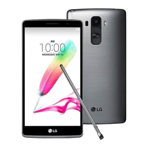
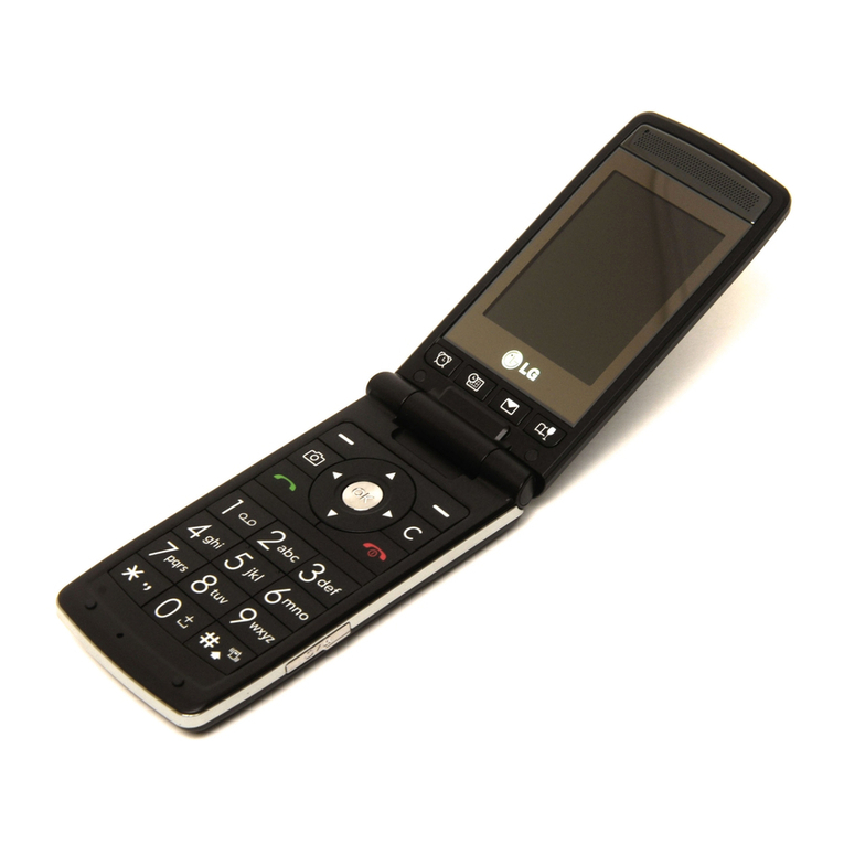
LG LGC-500W User manual

LGIC
LG Information & Communications, Ltd.
CDMA PORTABLE CELLULAR PHONE
LGC-500W
SERVICE MANUAL

LGC-500W
1
LGIC
LG Information & Communications, Ltd.
Table of Contents
General Introduction
.............................................................................................................................................................. 2
CHAPTER 1. System Introduction
1. System Introduction ......................................................................................................................................
2. Features and Advantages of CDMA Mobile Phone (For AMPS as well) .....................................................
3. Structure and Functions of CDMA Mobile Phone (For AMPS as well) .......................................................
4. Specification ..................................................................................................................................................
5. Installation .....................................................................................................................................................
CHAPTER 2. NAM Input Method(Inputting of telephone numbers included)
1. Telephone Number and NAM Programming Method ...................................................................................
CHAPTER 3. Circuit Description
1. RF Transmit/Receive Part .............................................................................................................................
2. Digital/Voice Processing Part .......................................................................................................................
Appendix
.................................................................................................................................................
1. Assembly and Disassembly Diagram
2. Block & Circuit Diagram
3. Component Layout
4. Part List
5. Accessories
- Desktop Charger
- Travel Charger
- Cigar Lighter Charger
- Hands Free Kit
6. WLPST ( LGIC Product Support Tool For Win95 )

LGC-500W
2
LGIC
LG Information & Communications, Ltd.
The LGC-500W cellular phone functions as both analog cellular phone worked in AMPS (Advanced Mobile
Phone Service) mode and digital cellular phone worked in CDMA (Code Division Multiple Access) mode.
CDMA mode applies the DSSS (Direct Sequence Spread Spectrum) technique that has been used in military.
This technique enable to share one frequency channel with many users in the same specific area. As a result, that
it increases the capacity 10 times more compared with that in the analog mode (AMPS) currently used.
Soft/Softer Handoff, Hard Handoff, and Dynamic RF power Control technologies are combined into this phone
to reduce the call being interrupted in a middle of talking over phone.
CDMA digital cellular network consists of MSC (Mobile Switching Office), BSC (Base Station Controller), BTS
(Base station Transmission System), and MS (Mobile Station). Communication between MS and BTS is
designed to meet the specification of IS-95A (Common Air Interface). MS meets the specifications of the below :
- IS-95A (Common Air Interface) : Protocol between MS and BTS
- IS-96A (Vocoder) : Voice signal coding
- IS-98 : Basic MS functions
- IS-126 : Voice loopback
- IS-99 : Short Message Service, Asynchronous Data Service, and G3 Fax Service
LGC-500W is composed of a transceiver, a desktop charger, two Li-Ion Batteries (1650mAh), a h
ands-free kit,
a travel charger. In digital mode, the hands-free kit is designed to operate in full duplex.
General Introduction

LGC-340/345W
LGIC
LG Information & Communications, Ltd.
1. Introduction to the Cellular System
1.1 Basic Concept for the Cellular System
The design objective of early mobile radio systems was to achieve a large coverage area by using a single, very
high powered transmitter with antenna mounted on the tall tower. While this approach achieved very good
coverage, it also meant that it was impossible to reuse those same frequency throughout the system. But the
increasing demand for mobile service required the radio telephone system to achieve high capacity with limited
radio spectrum, while at the same time covering very large areas.
The cellular concept was a major breakthrough in sloving the problem of spectral congestion and user capacity.
The cellular concept ,which starts from the frequency reuse technique, is a system level idea which calls for
replacing a single, high power transmitter (large cell) with many low power transmitter(small cells), each
providing coverage to only a small portion of the service area. Each base station is allocated a portion of the total
number of channels available to the entire system, and nearby base stations are assigned different groups of
channels so that all the available channels are assigned to a relative small number of neighboring base stations.
Neighboring base stations are assigned different groups of channels so that the interference between base stations
(and the mobile users under their control) is minimized. This technique is called channel assignment stategy.
In the cellular system,the channel handoff operation is inevitably needed to keep a call while a user moves one
cell to another. This function not only involves identifying a new base station, but also eruires that the voice and
control signals be allocated to channel associated with new base station. The handoff between different swithcing
systems is called roaming. It is call state can be maintained continuously by the information exchange between
switching systems when the busy subscriber moves from one cellular system area to the other cellular system
area.
1.2 Multiple Access Techniques for the Cellular System
In cellualr systems, it is often desirable to allow the subscriber to send simultaneously infoermation to the base
station while receiving information from the base station. This is called deplexing. Duplexing is done using
frequency or time domain rechniques. Frequency Division Duplexing(FDD) provides two distinct bands of
freqeuncies for every user. In FDD, any duplex channel actually consist of two simplex channels, and a device
called a duplexer is used inside handsets and base stations. Time Division Duplexing(TDD) uses time instead of
frequency to provide both a forward and reverse link. If the time split between the forward and reverse time slot
is small, then the transmission and reception of data appears simultaneous to the user.
Multiple access techniques are used to share the available channel resources(frequency bandwidth). Frequency
Division Multiple Access(FDMA), Time Division Multiple Access(TDMA), Code Division Multiple
Access(CDMA) are the three major techniques in cellular systems.
CHAPTER 1. System Introduction

LGC-340/345W
4
LGIC
LG Information & Communications, Ltd.
FDMA allocates a unique frequencys to a channel. These channels are assigned on demand to users who request
service. During the period of the call, no other user can share the same frequency band. In FDD systems, the
users are assigned a channel as a pair of frequencies; one frequency is used for the forward channel, while the
other frequency is used for the reverse channel. This system is called FDD/FDMA system. Most of analog
cellular systems(AMPS, E-AMPS, NMT, ETACS, JTACS, etc. ) are FDD/FDMA system.
TDMA systems devide the radio spectrum into time slots, and each slot only one user is allowed to ether transmit
or receive. Each user occupies a cyclically repeating time slot, so a channel may be thought of as particular time
slot that reoccurs every frame, where N time slots comprise a frame. TDMA systems can apply in both TDD and
FDD.
Code Division Multiple Access (CDMA) is a radically new concept in wireless communications. It has gained
widespread international acceptance by cellular radio system operators as an upgrade that will dramatically
increase both their system capacity and the service quality. It has likewise been chosen for deployment by the
majority of the winners of the United States Personal Communications System spectrum auctions. It may seem,
however, mysterious for those who aren't familiar with it. This site is provided in an effort to dispel some of the
mystery and to disseminate at least a basic level of knowledge about the technology.
CDMA is a radically new concept in wireless communications. It has gained widespread international acceptance
by cellular radio system operators as an upgrade that will dramatically increase both their system capacity and the
service quality. It has likewise been chosen for deployment by the majority of the winners of the United States
Personal Communications System spectrum auctions. It may seem, however, mysterious for those who aren't
familiar with it. This site is provided in an effort to dispel some of the mystery and to disseminate at least a basic
level of knowledge about the technology.
CDMA is a form of spread-spectrum, a family of digital communication techniques that have been used in
military applications for many years. The core principle of spread spectrum is the use of noise-like carrier waves,
and, as the name implies, bandwidths much wider than that required for simple point-to-point communication at
the same data rate. Originally there were two motivations: either to resist enemy efforts to jam the
communications (anti-jam, or AJ), or to hide the fact that communication was even taking place, sometimes
called low probability of intercept (LPI). It has a history that goes back to the early days of World War II.
The use of CDMA for civilian mobile radio applications is novel. It was proposed theoretically in the late 1940's,
but the practical application in the civilian marketplace did not take place until 40 years later. Commercial
applications became possible because of two evolutionary developments. One was the availability of very low
cost, high density digital integrated circuits, which reduce the size, weight, and cost of the subscriber stations to
an acceptably low level. The other was the realization that optimal multiple access communication requires that
all user stations regulate their transmitter powers to the lowest that will achieve adequate signal quality.
CDMA changes the nature of the subscriber station from a predominately analog device to a predominately
digital device. Old-fashioned radio receivers separate stations or channels by filtering in the frequency domain.
CDMA receivers do not eliminate analog processing entirely, but they separate communication channels by
means of a pseudo-random modulation that is applied and removed in the digital domain, not on the basis of

LGC-340/345W
5
LGIC
LG Information & Communications, Ltd.
frequency. Multiple users occupy the same frequency band. This universal frequency reuse is not fortuitous. On
the contrary, it is crucial to the very high spectral efficiency that is the hallmark of CDMA. Other discussions in
these pages show why this is true.
CDMA is altering the face of cellular and PCS communication by:
lDramatically improving the telephone traffic (Erlang) capacity
lDramatically improving the voice quality and eliminating the audible effects of multipath fading
lReducing the incidence of dropped calls due to handoff failures
lProviding reliable transport mechanism for data communications, such as facsimile and internet traffic
lReducing the number of sites needed to support any given amount of traffic
lSimplifying site selection
lReducing deployment and operating costs because fewer cell sites are needed
lReducing average transmitted power
lReducing interference to other electronic devices
lReducing potential health risks

LGC-340/345W
6
LGIC
LG Information & Communications, Ltd.
2. Features and Advantages of CDMA Mobile Phone (For AMPS as well)
2.1 Various Types of Diversities
When employing the narrow band modulation (30kHz band) that is the same as the analog FM modulation
system used in the existing cellular system, the multi-paths of radio waves create a serious fading. However, in
the CDMA broadband modulation(1.25MHz band), three types of diversities (time, frequency, and space) are
used to reduce the multi-path fading problems generated from radio channels in order to obtain high-quality calls.
Time diversity can be obtained through the use of code interleaving and error correction code whereas frequency
diversity can be obtained by spreading signal energy to more wider frequency band. The fading related to normal
frequency can affect the normal 200~300kHz among signal bands and accordingly, serious affect can be avoided.
Moreover, space diversity (also called path diversity) can be realized with the following three types of methods.
First, it can be obtained by the duplication of cell site receive antenna. Second, it can be obtained through the use
of multi-signal processing device that receives a transmit signal having each different transmission delay time and
then, combines them. Third, it can be obtained through the multiple cell site connection (Soft Handoff) that
connects the mobile station and more than two cell sites at the same time.
2.2 Power Control
The CDMA system utilizes the forward (from a base station to mobile stations) and backward (from the mobile
station to the base station) power control in order to increase the call processing capacity and obtain high-quality
calls. In case the originating signals of mobile stations are received by the cell site in the minimum call quality
level (signal to interference) through the use of transmit power control on all the mobile stations, the system
capacity can be maximized.
If the signal of mobile station is received too strong, the performance of that mobile station is improved.
However, because of this, the interference on other mobile stations using the same channel is increased and
accordingly, the call quality of other subscribers is reduced unless the maximum accommodation capacity is
reduced.
In the CDMA system, forward power control, backward open loop power control, and closed loop power control
methods are used. The forward power control is carried out in the cell site to reduce the transmit power on
mobile stations less affected by the multi-path fading and shadow phenomenon and the interference of other cell
sites when the mobile station is not engaged in the call or is relatively nearer to the corresponding cell site. This
is also used to provide additional power to mobile stations having high call error rates, located in bad reception
areas or far away from the cell site.
The backward open loop power control is carried out in a corresponding mobile station; the mobile station
measures power received from the cell site and then, reversely increases/decreases transmit power in order to
compensate channel changes caused by the forward link path loss and terrain characteristics in relation to the
mobile station in the cell site. By doing so, all the mobile office transmit signals in the cells are received by the
cell site in the same strength.
Moreover, the backward closed loop power control used by the mobile station to control power with the
commands issued out by the cell site. The cell site receives the signal of each corresponding mobile station and

LGC-340/345W
7
LGIC
LG Information & Communications, Ltd.
compares this with the pre-set threshold value and then, issues out power increase/decrease commands to the
corresponding mobile station every 1.25 msec (800 times per second).
By doing so, the gain tolerance and the different radio propagation loss on the forward/backward link are
complemented.
2.3 Voice Encoder and Variable Data Speed
The bi-directional voice service having variable data speed provides voice communication which employs voice
encoder algorithm having power variable data rate between the mobile telephone cell site and mobile station. On
the other hand, the transmit voice encoder performs voice sampling and then, creates encoded voice packets to be
sent out to the receive voice encoder, whereas the receive voice encoder demodulates the received voice packets
into voice samples.
One of the two voice encoders described in the above is selected for use depending on inputted automatic
conditions and message/data; both of them utilize four-stage frames of 9600, 4800, 2400, and 1200 bits per
second. In addition, this type of variable voice encoder utilizes adaptive threshold values when selecting required
data rate. It is adjusted in accordance with the size of background noise and the data rate is increased to high rate
only when the voice of caller is inputted.
Therefore, background noise is suppressed and high-quality voice transmission is possible under the environment
experiencing serious noise. In addition, in case the caller does not talk, data transmission rate is reduced so that
the transmission is carried out in low energy. This will reduce the interference on other CDMA signals and as a
result, improve system performance (capacity, increased by about two times).
2.4 Protecting Call Confidentiality
CDMA signals have the function of effectively protecting call confidentiality by spreading and interleaving call
information in broad bandwidth. This makes the unauthorized use of crosstalk, search receiver, and radio very
hard substantially. Also included is the encryption function on various authentication and calls specified in IS-95
for the double protection of call confidentiality.
2.5 Soft Handoff
The handoff , which is basic function of the cellular system, can maintain a call when user moves one cell site to
another. In analog cellular, the cell sites use different frequecy channel, the handoff means frequence change.
This mechanism also uses in CDMA. CDMA has many Frequency Allocation(FA)s. When the handoff carry out
between different Fas, it is called Hard Handoff. The soft handoff means the handoff without change of the FA.
During the soft hand, the cell site already in the busy state and the cell site to be engaged in the call later
participate in the call conversion. The call conversion is carried out through the original call connection cell site,
both cell sites, and then, new cell site. This method do not change frquency , so minimize call disconnection and
prevent the user from detecting the hand-off.

LGC-340/345W
8
LGIC
LG Information & Communications, Ltd.
2.6 Frequency Re-Use(Segmentation)and Sectorization
Unlike the existing analog cellular system, the CDMA system can reuse the same frequency at the adjacent cell
and accordingly, there is no need to prepare a separate frequency plan. Total interference generated on mobile
station signals received from the cell site is the sum of interference generated from other mobile stations in the
same cell site and interference generated from the mobile station of adjacent cell site. That is, each mobile station
signal generates interference in relation to the signals of all the other mobile signals.
Total interference from all the adjacent cell sites is the ratio of interference from all the cell sites versus total
interference from other mobile stations in the same cell site (about 65%). In the case of directional cell site, one
cell normally uses a 120¡Æsector antenna in order to divide the sector into three. In this case, each antenna is
used only for 1/3 of mobile stations in the cell site and accordingly, interference is reduced by 1/3 on the average
and the capacity that can be supported by the entire system is increased by three times.
2.7 Soft Capacity
The subscriber capacity of CDMA system is flexible depending on the relation between the number of users and
service classes. For example, the system operator can increase the number of channels available for use during
the busy hour despite the drop in call quality. This type of function requires 40% of normal call channels in the
standby mode during the handoff support, in an effort to avoid call disconnection resulting from the lack of
channels.
In addition, in the CDMA system, services and service charges are classified further into different classes so that
more transmit power can be allocated to high class service users for easier call set-up; they can also be given
higher priority of using hand-off function than the general users.

LGC-340/345W
9
LGIC
LG Information & Communications, Ltd.
3. Structure and Functions of CDMA Mobile Phone (For AMPS as well)
The mobile station of CDMA system is made up of a radio frequency part and logic/control (digital) part. The
mobile station is fully compatible with the existing analog FM system. The mobile station antenna is connected
with the transmitter/receiver via a duplexer filter so that it can carry out the transmit/receive function at the same
time.
The transmit frequency is the 25MHz band of 824~849MHz, whereas the receive frequency is the 25MHz band
of 869~894MHz. The transmit/receive frequency is separated by 45MHz. The RF signal from the antenna is
converted into intermediate frequency(IF) band by the frequency synthesizer and frequency down converter and
then, passes the bandpass SAW filter having the 1.25MHz band. IF output signals that have been filtered from
spurious signal are converted into digital signals via an analog-to-digital converters(ADC) and then, sent out
respectively to 5correlators in each CDMA de-modulator. Of these, one is called a searcher whereas the
remaining 4are called data receiver(finger). Digitalized IF signals include a great number of call signals that
have been sent out by the adjacent cells. These signals are detected with pseudo-noise sequence (PN Sequence).
Signal to interference ratio (SINAD) on signals that match the desired PN sequence are increased through this
type of correlation detection process. Then, other signals obtain processing gain by not increasing the ratio. The
carrier wave of pilot channel from the cell site most adjacently located is demodulated in order to obtain the
sequence of encoded data symbols.
During the operation with one cell site, the searcher searches out multi-paths in accordance with terrain and
building reflections. On three data receivers, the most powerful four paths are allocated for the parallel tracing
and receiving. Fading resistance can be improved a great deal by obtaining the diversity combined output for de-
modulation. Moreover, the searcher can be used to determine the most powerful path from the cell sites even
during the soft handoff during the two cell sites. Moreover, four data receivers are allocated in order to carry out
the de-modulation of these paths. Data output that has been demodulated change the data string in the combined
data row as in the case of original signals(deinterleaving), and then, are de-modulated by the forward error
correction decoder which uses the Viterbi algorithm.
On the other hand, mobile station user information sent out from the mobile station to the cell site pass through
the digital voice encoder via a mike. Then, they are encoded and forward errors are corrected through the use of
convolution encoder. Then, the order of code rows is changed in accordance with a certain regulation in order to
remove any errors in the interleaver. Symbols made through the above process are spread after being loaded onto
PN carrier waves. At this time, PN sequence is selected by each address designated in each call.
Signals that have been code spread as above are digital modulated (QPSK) and then, power controlled at the
automatic gain control amplifier (AGC Amp). Then, they are converted into RF band by the frequency
synthesizer synchronizing these signals to proper output frequencies. Transmit signals obtained pass through the
duplexer filter and then, are sent out to the cell site via the antenna.

LGC-340/345W
10
LGIC
LG Information & Communications, Ltd.
4. Specification
4.1 General Specification
4.1.1 Transmit/Receive Frequency Interval : 45 MHz
4.1.2 Number of Channels (Channel Bandwidth)
1) CDMA : 20 CH
2) AMPS : 832 CH
4.1.3 Operating Voltage : DC 3.6V
4.1.4 Battery Power Consumption : DC 3.5V
SLEEP IDLE MAX POWER
CDMA 2.3 mA103 mA 740 mA (24 dBm)
AMPS ¦¡99 mA 845 mA (28 dBm)
4.1.5 Operating Temperature : -30
°
~ +60
°
4.1.6 Frequency Stability
1) CDMA :¡¾0.5PPM
2) AMPS : ¡¾2.5PPM
4.1.7 Antenna : Retractable Type (Herical+Whip), 50
Ω
4.1.8 Size and Weight
1) Size :120 547.3 527 §§(Batt : STD )
120 547.3 523.2§§(Batt :Option)
2) Weight : 140 ~150g(Batt : STD )
120 ~ 130g (Batt : Option)
4.1.9 Channel Spacing
1) CDMA : 1.25MHz
2) AMPS : 30KHz
4.1.10 Battery Type, Capacity and Orerating Time.
Unit = Hours : Minutes
Standard
(1400mA)
Option
(900mA)
CDMA 240 Hrs 140 Hrs
Stand-By Time AMPS 25 Hrs 15Hrs

LGC-340/345W
11
LGIC
LG Information & Communications, Ltd.
CDMA 300 Mins 180 Mins
Talk Time AMPS 140 Mins 90 Mins
4.2 Receive Specification
4.2.1 Frequency Range
1) Digital : 869.820 MHz ~ 893.190 MHz
2) Analog : 869.04 MHz ~ 893.97 MHz
4.2.2 Local Oscillating Frequency Range : 966.88MHz
¡¾
12.5MHz
4.2.3 Intermediate Frequency : 85.38MHz
4.2.4 Sensitivity
1) CDMA : -104dBm (C/N 12dB or more)
2) AMPS : -116dBm (12dB SINAD)
4.2.5 Selectivity
1) CDMA : 3dB C/N Degration (With Fch¡¾1.25 kHz : -30dBm)
2) AMPS : 16dB at Fch¡¾30kHz, 60 dB at Fch¡¾60kHz
4.2.6 Spurious Wave Suppression : Maximum of -80dB
4.2.7 CDMA Input Signal Range
•Dynamic area of more than -104~ -25 dB : 79dB at the 1.23MHz band.
4.2.8 AMPS DE-Emphasis : -6dB/OCT within 0.3~3kHz
4.2.9 AMPS Expander
1) Expansion Rate : 1:2
2) Attack Time : within 3mS
3) Recovery Time : within 13.5mS
4) Reference Input : Output level to a 1000Hz tone from a carrier
within +2.9kHz peak frequency deviation.
4.2.10 AMPS Sensitivity : 12dB SINAD/-116dBm
4.2.11 AMPS Intermodulation Spurious Response Attenuation : Above 65dB
4.2.12 AMPS RSSI Range : Above 60dB
4.2.13 AMPS Protection Against Spurious Response Interference : Above 60dB

LGC-340/345W
12
LGIC
LG Information & Communications, Ltd.
4.2.14 AMPS In Band Conducted Spurious Emissions
1) Transmit Band : below –60dBm
2) Receive Band : below –80dBm
4.2.15 AMPS Out of Band Conducted Spurious Emissions : Below -47dBm
4.2.16 AMPS Radiated Spurious Emissions
Frequency Range Maximum allowable EIRP
25 ~ 70 kHz
70 ~ 130 kHz
130 ~ 174 kHz
174 ~ 260 kHz
260 ~ 470 kHz
470 ~ 1 GHz
- 45 dBm
- 41 dBm
- 41 ~ - 32 dBm
- 32 dBm
- 32 ~ - 26 dBm
- 21 dBm
4.3 Transmit Specification
4.3.1 Frequency Range
1) Digital : 824.820MHz ~ 848.190MHz
2) Analog : 824.04MHz ~ 848.97MHz
4.3.2 Local Oscillating Frequency Range : 966.88 MHz
¡¾
12.5 MHz
4.3.3 Intermediate Frequency : 130.38 MHz
4.3.4 Output Power
1) CDMA : 0.32W
2) AMPS : 0.6W
4.3.5 Interference Rejection
1) Single Tone : -30dBm at 900 kHz
2) Two Tone : -43dBm at 900 kHz & 1700kHz
4.3.6 AMPS Carrier ON/OFF Conditions
“ON”condition : within +3dB of specification output (in 2mS)
4.3.7 AMPS Compressor
•Compression Rate : 2:1
•Attack Time : 3mS
•Recovery Time : 13.5mS

LGC-340/345W
13
LGIC
LG Information & Communications, Ltd.
•Reference Input : Input level for producing a nominal +2.9kHz peak requency deviation
of transmitted carrier.
4.3.7 AMPS Preamphasis : 6dB/OCT within 0.3 ~ 3 kHz
4.3.8 AMPS Maximum Frequency Deviation
•F3 of G3 : ¡¾12kHz (¡¾10% )
•Supervisory Audio Tone : ¡¾2kHz (¡¾10% )
•Signaling Tone : ¡¾8kHz (¡¾10%)
•Wideband Data : ¡¾8kHz (¡¾10 %)
4.3.9 AMPS Post Deviation Limiter Filter
•3.0kHz ~ 5.9kHz : above 40LOG (F/3000) dB
•5.9kHz ~ 6.1kHz : above 35dB
•6.1kHz ~ 15kHz : above 40LOG (F/3000) dB
•Over 15kHz : above 28dB
4.3.10 AMPS Spectrum Noise Suppression
•For all Modulation
fo+20kHz ~ fo+45kHz : above 26dB
•For Modulation by Voice and SAT
fo+45kHz : above 63+10LOG (Py) dB
•For Modulation by WBD ( without SAT ) and ST ( with SAT )
fo+45kHz ~ fo+60kHz : above 45dB
fo+60kHz ~ fo+90kHz : above 65dB
fo+90kHz ~2fo: above 63+10LOG (Py) dB
(where fo=carrier frequency,Py=mean output power in watts)
4.3.11 AMPS Harmonic and Conducted Spurious Emissions : above 43+10LOG (Py) dB
4.3.12 CDMA TX Frequency Deviation : +300Hz or less
4.3.13 CDMA TX Conducted Spurious Emissions
•900kHz :- 42 dBc/30kHz below
•1.98MHz : - 54 dBc/30kHz below
4.3.14 CDMA Minimum TX Power Control : - 50dBm below

LGC-340/345W
14
LGIC
LG Information & Communications, Ltd.
4.4 MS (Mobile Station) Transmitter Frequency
FA NO. CH.NO. CENTER FREQUENCY FA NO. CH.NO. CENTER FREQUENCY
1
2
3
4
5
6
7
8
9
10
1011
29
70
111
152
193
234
275
316
363
824.640 MHz
825.870 MHz
827.100 MHz
828.330 MHz
829.560 MHz
830.790 MHz
832.020 MHz
833.250 MHz
834.480 MHz
835.890 MHz
11
12
13
14
15
16
17
18
19
20
404
445
486
527
568
609
650
697
738
779
837.120 MHz
838.350 MHz
839.580 MHz
840.810 MHz
842.04 MHz
843.270 MHz
844.500 MHz
845.910 MHz
847.140 MHz
848.370 MHz
4.5 MS (Mobile Station) Receiver Frequency
FA NO. CH.NO. CENTER FREQUENCY FA NO. CH.NO. CENTER FREQUENCY
1
2
3
4
5
6
7
8
9
10
1011
29
70
111
152
193
234
275
316
363
869.640 MHz
870.870 MHz
872.100 MHz
873.330 MHz
874.560 MHz
875.790 MHz
877.020 MHz
878.250 MHz
879.480 MHz
880.890 MHz
11
12
13
14
15
16
17
18
19
20
404
445
486
527
568
609
650
697
738
779
882.120 MHz
883.350 MHz
884.580 MHz
885.810 MHz
887.04 MHz
888.270 MHz
889.500 MHz
890.910 MHz
892.140 MHz
893.370 MHz
4.6 Desktop Charger : See Appendix
4.7 Travel Charger : See Appendix
4.8 Cigar Lighter Charger : See Appendix
4.9 Hands-Free Kit : See Appendix

LGC-340/345W
15
LGIC
LG Information & Communications, Ltd.
5. Installation
5.1 Installing a Battery Pack
1) The Battery pack is keyed so it can only fit one way. Align the groove in the battery pack with the rail on the
back of the phone until the battery pack rests flush with the back of the phone.
2) Slide the battery pack forward until you hear a “click”, which locks the battery in place.
5.2 For Desktop Charger Use
1) Plug the charger into a wall outlet. The charger can be operated from either a 110V or a 220V source. When
AC power is connected to the desktop charger, both the green and red LED’s blink once.
2) Insert the phone with the installed battery pack or a spare battery pack into the individual battery pack slot.
Red light indicates battery is being charged.. Green light indicates battry is fully charged.
5.3 For Mobile Mount
5.3.1 Installation Position
In order to reduce echo sound when using the Hands-Free Kit, make sure that the speaker and microphone are not
facing each other and keep microphone a generous distance from the speaker.
5.3.2 Cradle Installation
Choose an appropriate flat surface where the unit will not interface with driver’s movement or passenger’s
comfort. The driver/user should be able to access the phone with ease. Using the four self-tapping screws
provided, mount the supplied braket on the selected area. Then with the four machine screws provided, mount the
counterpart on the reverse side of the reverse side of the cradle. Secure the two brackets firmly together by using
the two bracket joint screws provide. The distance between the cradle and the interface box must not exceed the
length of the main cable.
5.3.3 Interface Box
Choose an appropriate flat surface ( somewhere under the dash on the passenger side is preferred ) and mount the
IB bracket with the four self-tapping screws provided. Clip the IB into the IB bracket.
5.3.4. Microphone Installation
Install the microphone either by cliiping Ionto the sunvisor (driver’s side) or by attaching it to door post
(driver’s side), using a velcno adhesive tape (not included).

LGC-340/345W
16
LGIC
LG Information & Communications, Ltd.
5.3.5 Cable Connections
5.3.5.1 Power and Ignition Cables
Connect the red wire to the car battery positive terminal and the black wire to the car ground. Connect the green
wire to the car ignition sensor terminal. ( In order to operate HFK please make sure to connect green wire to
ignition sensor terminal.) Connect the kit’s power cable connector to the interface box power receptacle.
5.3.5.2 Antenna Cable Connection
Connect the antenna coupler cable connector from the cradle to the external antenna connector. ( Antenna is not
included.)

LGC-340/345W
17
LGIC
LG Information & Communications, Ltd.
1. Telephone Number and NAM Programming Method
•Press MENU+4+0 and then, press the password made up of six digits(Default:000000).
Then, the following Menu is appeared.
•Press 1to program the telephone number and NAM.
•Select one NAM (the registration requiresNAM1 as default).
•Edit ESN(if you want, but not recommended) , then press [OK].
•Enter the phone number, then press [OK].
•Edit NAM 1 HOME SID, then press [OK].
CHAPTER 2. NAM Input Method
(Inputting of telephone numbers included)
1 : NAM 1
2:NAM 2
3 : NAM 3
4 : NAM 4
1 : Prog Mode
2:Pref. Mode
3 : ER Mode
4 : PRL
ESN
NAM 1 PHONE
NUMBER
NAM 1 HOME SID

LGC-340/345W
18
LGIC
LG Information & Communications, Ltd.
•Edit the name of NAM1, the press [OK]. ‘NAM 1 NAME’may display the name of the service provider.
•Now, the basic programming is completed. To reset the handset, press [EXIT]. If you want to program
detail informtions for NAM 1, press [MORE].
The detail programming method is same as basic programming. Set up required values and then, press the [OK]
soft key in an effort to move to the next screen. To return to the last item, press the left arrow (3*). The editable
NAM items are followed:
SERVICE SEC. CODE
NAM 1 LOCK_OUT SYSTEM 1
NAM 1 CDMA PHONE MUNBER
NAM 1 MOBILE COUNTRY CODE
NAM 1 MOBILE NETWORK CODE
NAM 1 MOBILE STATION ID #
NAM 1 CDMA HOME SID 1
NAM 1 CDMA HOME NID 1
NAM 1 CDMA HOME SID 2
NAM 1 CDMA HOME NID 2
NAM 1 CDMA HOME SID 3
NAM 1 CDMA HOME NID 3
NAM 1 CDMA HOME SID 4
NAM 1 CDMA HOME NID 4
NAM 1 AMPS PHONE NUMBER
NAM 1 AMPS HOME SID
PHONE MODEL
SLOT CYCLE INDEX
¡ØEditing this items is not recommended.
NAM 1 NAME
BASIC NAM 1
PROGRAMMING
IS COMPLETED

LGC-340/345W
19
LGIC
LG Information & Communications, Ltd.
1. RF Transmit/Receive Part
1.1 Overview
The RF transmit/receive part employs the Super-Heterodyne system. The transmit/receive frequency is
respectively 824.04~848.97 MHz and 869.04~893.97 MHz and the block diagram is shown in Appendix 4.
RF signals received through the antenna are fed into the low noise amplifier (LNA) through the duplexer. Then,
they are combined with the signals of local oscillator (VCO) at the frequency mixer in order to create
intermediate frequency (IF).
Intermediate frequency created is sent out to each bandpass filter (BPF) through the FM (Analog) or CDMA
(Digital) path and then,fed into IFR (RX IF BASEBAND converter), signals are auto gain controlled and, are
changed into baseband signals.
These signals are then, changed into digital signals by the analog/digital converter (ADC, A/D Converter) and
then, sent to the MSM (Mobile Station Modem) of the digital circuit part. Then, they are demodulated by the
modulator/demodulator.
In the case of transmission, IFT receives modulated digital signals from the MSM of the digital circuit and then,
changes them into analog signals by the digital/analog converter (DAC, D/A Converter) in order to create
baseband signals. Created baseband signals are changed into IF signals by IFT and then, are auto gain controlled.
IF signals that have been fed are mixed with the signals of VCO and changed into the RF signals and amplified
with dynamic range.
They are amplified at the Power AMP. Finally, they are sent out to the cell site via the antenna after going
through the isolator and duplexer.
Block Diagram of RF
Local circuit
Power
AMP
Up
mixer
Drive
AMP
LNA
Down
Mixer
IF
AMP
Dupl
exer
SAW
Filter
TX RF
SAW
Filter
RX RF
SAW
Filter
PLLVCO VC -
Tcxo
RF IF
TX
Tank
IFT3000
RX
Tank IFR3000
CDMA IF
SAW Filter
DFM IF
SAW Filter
19.68M Hz
19.68M Hz
PA_ON TX_AGC_ADJ
LNA_Range SYNTH_LOCK
Isolator
[Figure 1-1] Block Diagram of RFTransmit/Receive Part
CHAPTER 3. Circuit Description
Other manuals for LGC-500W
1
Table of contents
Other LG Cell Phone manuals