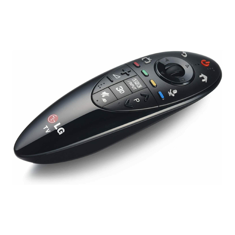
LG PQWRHSF0 User manual

Controller accessories 363
Wireless remote controller
1. Controller accessories
1.1 Wireless remote controller
Picture:
Functions:
A Wireless remote controller allows the operation of air conditioner from any corner of the room
Applicable Models:
Ceiling cassete
Ceiling concealed duct
Accessory:
Wireless remote control ............................................................................................................................1EA
Owner's manual ........................................................................................................................................1EA
AHWRHSAHWRHDPQWRHSF0
Functions PQWRHSF0 AHWRHD AHWRHS
Air circulation / Fan operation
Room temperature checking
Sleep mode operation
Temperature settings
Operation mode selection
Air-swing & Jet cool (Cassette Only)
On/Off Timer settings

364 Controller accessories
Wireless remote controller
Installation procedure:
Mounting on the wall
1) Mount the remote control stand on the wall with the help of screw driver and screw pur-
chased locally.
2) Insert the remote control in the stand.
How to insert batteries:
1) Remove the battery cover from the remote control. Slide the cover in the direction of arrow.
2) Insert two batteries. Take care about the polarity(+/-) and batteries should be new.
3) Re-place the cover by sliding it back into position.
How to use
For ceiling cassette :
Point the signal transmitter towards the front panel of the cassette indoor unit (for C, D, E, F
Chassis models) and press any function key. For B chassis point the signal transmitter towards
the wired remote control and press any function key.
For ceiling concealed duct, ducted split & Single package :
Point the signal transmitter towards the wired remote control and press any function key.
Remarks
1. Do not use rechargeable batteries for wireless remote control .
2. Remove the batteries from the remote control if the air conditioner is not going to be used for
long time.

Controller accessories 365
Wireless remote controller
Function's detail
Models : PQWRHSF0
The remote control transmits the signals to the system.
START/STOP BUTTON
Operation starts when this button is pressed and stops
when the button is pressed again.
Operation mode selection button
Used to select the operation mode.
ROOM TEMPERATURE SETTING BUTTONS
Used to select the room temperature.
INDOOR FAN SPEED SELECTOR
Used to select fan speed in four steps
low, medium, high and CHAOS.
JET COOL
Used to start or stop the speed
cooling. (Speed cooling operates
super high fan speed in cooling mode.)
CHAOS SWING BUTTON
Used to stop or start louver movement and set the desired
up/down airflow direction.
ON/OFF TIMER BUTTONS
Used to set the time of starting and stopping operation.
TIME SETTING BUTTONS
Used to adjust the time.
TIMER SET/CANCEL BUTTON
Used to set the timer when the desired time is obtained and
to cancel the Timer operation.
SLEEP MODE AUTO BUTTON
Used to set Sleep Mode Auto operation.
AIR CIRCULATION BUTTON
Used to circulate the room air without cooling or heating.
ROOM TEMPERATURE CHECKING BUTTON
Used to check the room temperature.
PLASMA(OPTIONAL)
Used to start or stop the plasma-purification function.
HORIZONTAL AIRFLOW DIRECTION CONTROL
BUTTON (NOT ON ALL MODELS)
Used to set the desired horizontal airflow direction.
RESET BUTTON
Used prior to resetting time or after replacing batteries.
2nd F Button
Used prior to using modes printed in blue at the bottom of
buttons.
AUTO CLEAN(OPTIONAL)
Used to set Auto Clean mode.
1.
2.
3.
4.
5.
6.
7.
8.
9
10.
11.
12.
13.
14.
15.
16.
17.
ON OFF
CANCEL
SET
1
3
5
4
9
10
12
14
16
7
2
8
13
15
11
6
Cooling Operation
Auto Operation or Auto Changeover
Healthy Dehumidification Operation
Flip-up door
(opened)
Heating Operation
Signal transmitter
•
Cooling Model( ), Heat Pump Model( )
17
AUTO CLEAN
Operation Mode
366 Controller accessories
Wireless remote controller
Models : AHWRHD
1. Operation display
Displays the operation conditions.
2. Start/Stop button
Operation starts when this button is pressed and stops
when the button is pressed again.
3. Operation mode selection button
Used to select the operation mode.
4. on/off timer buttons
Used to set the time of starting and stopping operation.
5. Time setting buttons
Used to adjust the time.
6. timer set/cancel buttons
Used to set the timer when the desired time is obtained
and to cancel the Timer operation.
7. Air flow direction start/stop button
Used to stop or start louver movement and set the
desired up/down airflow direction.
8. Sleep mode auto button
Used to set Sleep Mode Auto operation.
9. Air circulation button
Used to circulate the room air without cooling or heating
(turns indoor fan on/off).
10. room temperature checking button
Used to check the room temperature.
11. Reset button
Used prior to resetting time or after replacing batteries.
ON OFF
SET
CANCEL
Signal transmitter
Flip-up door(opened)
1
7
2
8
9
10
11
3
4
5
6

Controller accessories 367
Wireless remote controller
Models : AHWRHS
Signal transmitter
Transmits the signals to the signal receptor.
1. FAN operation button
Used to circulate room air without cooling or heating.
2. Cooling operation button
3. Soft dry operation button
Used to dehumidify without overcooling.
4. Heating operation button
(Heat pump model only)
5. Timer set button
Used to set the timer when the desired time is obtained.
Then the wired remote controller is set up to 24 hours by
an hour but the wireless remote controller is set up to 7
hours by an hour. Therefore, if you want to set over 7
hours, use the wired remote controller.
6. Fan speed button
Used to set the desired fan speed.
7. On/Off button
Operation starts when this button is pressed, and stops
when the button is pressed again.
8. Set temperature button
Used to set the temperature when the desired tempera-
ture is obtained
9. Auto operation button
A/CL
7
9
2
8
5
6
4
1
3

368 Controller accessories
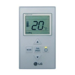
Simple wired remote control
1.2 Simple wired remote controller
Picture:
Applicable models
Cassette, duct and ceiling and floor
Functional control
Dimension
PQRCHCS0
FAN
SPEED
MODE
Cooling Heating Auto Dry Fan
Defrost Preheat Out door
Slo
Lo
Med
Hi
Po
Room Temp
Total on
Central Run
1
2
3
4
5
PQRCHCS0
FAN
SPEED
MODE
Cooling Heating Auto Dry Fan
Defrost Preheat Out door
Slo
Lo
Med
Hi
Po
Room Temp
Total on
Central Run
120mm
70mm
13.5mm
Functional description:
1. Simple design.
2. Simple & easy use.
3. Memorize data(operation data) in case of power failure.
4. ON/OFF , Temperature setting, room temperature display,
Air flow control, lock setting, Fault diagnosis function,
operation mode setting, basic functions.
5. Easy address setting with central control.
6. Operation LED is on during operation.
1. Operation Display Panel
2. On/off Function
3. Fan Speed Button
4. Temperature Control Button
5. Mode Selection Check Button
Models : PQRCUCA0

Controller accessories 369
Simple wired remote control
Installation method:
1 Put the installation paper on the place and determine the position and height of the fixing screws of the wired remote con-
troller.
• Refer to the printed side of the installation paper.
2 Plug the connecting cable into the indoor unit.
• The product is being shipped with the cable connected only to the remote controller.
Fix the connecting cable with the cable rack.
3 Remove the installation paper before installing the remote controller so that it can fit at the right place.
* Do not embed the remote controller into the wall. (It may cause the breakdown of the temperature sensor.)
* If you want to install a number of remote controller at the same place in a vertical line, install them at regular intervals of
2cm. (It may cause the breakdown of the temperature sensor.)
* Do not install the cable with a distance of 30 m or longer. (This can cause communication error.)
* When installing the cable, check whether the connector between the remote controller and the product is installed prop-
erly. The connector will not be connected when installed in opposite sides.
o Supply the power after connecting wired remote controller.
When you need to change wired remote controller, switch off the main power and change it.
If the wired remote controller is changed before switching off the main power, the option function of the indoor unit can't
be used. (option function like "slow" fan speed selection)
The position of the fixing screws
CN-REMO
LO2K
J15
LO1K
LO1D C07D
C01K
J14
CN-DISP
CN-M CN-ZONEC
IC01A
Side of
remote Controller
Side of
Indoor Unit
Main
indoor unit
Red Yellow Brown
Main frame
Fixing the
remote controller
2CM

370 Controller accessories
Deluxe wired remote controller
1.3 Deluxe wired remote controller
Models : PQRCUDS0
Picture:
Applicable models
Cassette, duct and ceiling and floor
Functional control
1
2
3
4
6
5
7
8
9
10
15
14
12
20
11
19
16
17
18
13
Functional Description:
1. Big LCD panel which can display various information.
2. Deluxe touch panel.
3. Memorize data(operation data) in case of power failure.
4. ON/OFF,Temperature setting, room temperature display,
5. Air flow control, lock setting,reservation function,
6. Fault diagnosis function, operation mode setting, basic
functions.
7. Easy address setting with central control.
8. Deluxe with LCD back light applied
9. Vane control & child lock, optimum air control as deluxe
function
10. Back light LED is on during operation.
1. Operation Display Panel
2. Room Temperature Button
3. Fan Speed Button
4. Fan/Plasma/Swirl Swing Button
5. Automatic / Power Saving Vane Control Button
6. Timer Mode Button
7. Date Selection Button
8. Hour/Minute Button
9. Mode Selection Button
10. On/Off Button for reservation
11. Temperature Control Button
12. On/Off Button
13. Special Function Button
14. Dehumidification/ Heater/ Go-out Button
15. Sub Function Button
16. Easy Reservation Button
17. Cancel Button
18. Heating/Ventilation/Elevation Grill Button
19. Setting Button
20. Cooling / Auto Swing / Child Lock Button

Controller accessories 371
Deluxe wired remote controller
Installation method:
1 Put the installation paper on the place and determine the position and height of the fixing screws of the wired remote con-
troller.
• Refer to the printed side of the installation paper.
2 Plug the connecting cable into the indoor unit.
• The product is being shipped with the cable connected only to the remote controller. Put each cable to the remote con-
troller according to the color match
3 Remove the installation paper before installing the remote controller so that it can fit into the right place.
* When installing the wired remote controller, do not install it so that it is buried to the wall. (This can cause error in the
temperature sensor)
* When installing multiple wired remote controllers horizontally in one location, leave a minimum distance apart (2cm).
(This can cause error in the temperature sensor)
* Do not install the cable with a distance of 50 m or longer. (This can cause communication error.)
* When installing the cable, check whether the connector between the remote controller and the product is installed prop-
erly. The connector will not be connected when installed in opposite sides.
JSupply the power after connecting wired remote controller.
When you need to change wired remote controller, switch off the main power and change it Before switch off the main
power if changed the wired remote controller , you can't use the option function of the indoor unit.
The position of the fixing screws
Side of
remote Controller
Side of
Indoor Unit
Main frame
CN-REMO
LO2K
"15
LO1K
LO1D C07D
C01K
"14
CN-DISP
CN-M CN-ZONEC
IC01A
Be careful not to alter the colors
of the remote controller
connection cables.
Brown
Red YellowYellowYellow
Fixing the
remote controller
Fixing the
connecting cable

372 Controller accessories
Hotel use remote controller
1.4 Hotel use remote controller
Models : PQRCFCS0
Picture:
Applicable models
Cassette, duct and ceiling and floor
Functional control
PQRCHCS0
FAN
SPEED
MODE
Cooling Heating Auto Dry Fan
Defrost Preheat Out door
Slo
Lo
Med
Hi
Po
Room Temp
Total on
Central Run
1
2
3
4
5
Functional description:
Can control one or multi indoor units which have been
installed at remote areas with same function by same con-
troller at same time
1. Simple design.
2. Simple & easy use.
3. Memorize data(operation data) in case of power failure.
4. ON/OFF , Temperature setting, room temperature display,
Air flow control, lock setting, Fault diagnosis function,
operation mode setting, basic functions.
5. Easy address setting with central control.
6. Operation LED is on during operation.
7. Operation mode setting can be done by central control
1. Operation Display Panel
2. On/off Function
3. Fan Speed Button
4. Temperature Control Button
5. Room temperature button

Controller accessories 373
Hotel use remote controller
Dimension
Operation
1. LCD Panel to show various information.
2. Can check indoor operation status by Key.
3. Memorize data(operation data) in case of power failure.
4. ON/OFF , Temperature setting, room temperature display, Air flow control, lock setting, Fault diagnosis function, opera-
tion mode setting, basic functions, reservation function, Clock function.
5. Easy address setting with central control.
1. Two types of controller CST/DUCT.
2. Can control one or multi indoor units which have been installed at remote areas with same function by same controller at
same time.
NOTE
PQRCHCS0
FAN
SPEED
MODE
Cooling Heating Auto Dry Fan
Defrost Preheat Out door
Slo
Lo
Med
Hi
Po
Room Temp
Total on
Central Run
120mm
70mm
13.5mm

374 Controller accessories
Zone Control
1.5 Zone Control
Picture
Applicable models
Ceiling concealed duct
Accessory
Models : ABZCA
• Factory Supplied :
- Zone Control PCB............................................................................................................................................................1EA
- Trans................................................................................................................................................................................1EA
- Case ................................................................................................................................................................................1EA
- Cover ...............................................................................................................................................................................1EA
- Main lead wires................................................................................................................................................................1EA
- Screws .............................................................................................................................................................................4EA
- Holder ..............................................................................................................................................................................4EA
- Installation Manual................................................................................................................................................................1
• Purchased Locally :
- Damper Motor
- Thermostat
- Damper
ROOM1 Thermostat
ROOM3 Thermostat
Zone Control
sub PCB
ROOM4 Thermostat
Damper Motor
Damper Motor
Damper Motor
Damper Motor
ROOM2 Thermostat
Functional Description:
1) Operation Summary
A device which senses temperature of each zone controls
operation of each diffuser,so temperature of each zone
can be controlled.
2) Specific Operation
- If every zone (diffuser) is closed, Comp and outer fan
become turned off to protect compressor.
* Zone controller requires diffuser temperatures and con-
trollers available locally.
3) Operating Scene
• The temperature of all zones are controlled individually
(makes energy savings) controlled by the signal of every
zones in duct system (By connecting the thermostat
and VAV Diffuser to Main PCB,comp. & fan)
• Diffuser and Thermostat are locally sourced Connected
to Another Apparatus, Control it Freely.

Controller accessories 375
Zone Control
Indoor Unit
Main"
PCB
Damper"
Motor"
"1
Damper"
Motor"
"2
Damper"
Motor"
"3
Damper"
Motor"
"4
CH1
CH2
CH3
CH4
COM
COM
COM
COM
AC 24V
24V
24V
24V
Trans
Trans : 12VA"
(24V/130mA*4)
AC220~240V 50/60Hz
Zone"
Controller"
PCB N
LLL L
NNN
Thermostat " 1
Thermostat " 2
Thermostat " 3
Thermostat " 4
Damper"
Motor"
"1
Damper"
Motor"
"2
Damper"
Motor"
"3
Damper"
Motor"
"4
N
SSS S
NN N
Thermostat " 1
Thermostat " 2
Thermostat " 3
Thermostat " 4
AC(L) AC(N)
Power Input
Indoor Unit
Main"
PCB
CH1
CH2
CH3
CH4
COM
COM
COM
COM
AC 24V
24V
24V
24V
Trans
Trans : 12VA"
(24V/130mA*4)
AC220~240V 50/60Hz
L": Live"
N": Neutral"
S": Signal
Zone"
Controller"
PCB
AC(L) AC(N)
Power Input
HVAC
By-pass damper
24 VCA"
power supply
Return Supply
Static"
pressure "
control
40 VA"
transformer NC NO
Pressure controller
Closed
Common
3-channel damper motor
Open
1"
"
2"
"
3"
"
• Spring Return Damper Actuators
• Non Spring Return Damper Actuators
By Pass Damper System :-
To maintain an adequate flow of air and static pressure through the HVAC system, a by-pass system can be used that is
equipped with a motorized damper and a static pressure control.
Installation method:
• Connect main lead wires between main PCB and Zone Control.
• Connect thermostat to Zone Control according to thermostat maker's manuals.
• Connect Damper Motor to Zone Control according to Damper Motor maker's manuals.
• Wiring also depends upon the type of the damper actuators.

376 Controller accessories
Zone Control
When the area dampers open or close, the static pressure control will open or close the by-pass damper so as to maintain
the adequate static pressure. Dimensions of the by-pass damper depends on the cooling capacity of the unit.
Remarks:
• Turn off the Power before installation or maintenance.
Btu/h Size of the by-pass (ø)
36K 250 mm
42K 250 mm
48K 300 mm
60K 300 mm
91K 350 mm
120K 350 mm
* Central
Contr oller
* Central
Sub PCB
Indoor Unit
**Main Pcb
** Display PCB
Outdoor Unit
In case of 220V Damper,
attach AC 24V Relay
** Wir ed
Remote
Contr oller
*RF
Remote
Contr oller
* Zone
Contr oller
Sub Pcb
AC 24V
Transformer
Damper
"1
Damper
"2
Damper
"3
Damper
"4
Array of PCB & Controllers
Local sourcing components
Relay
Relay
Relay
Relay
Thermostat " 1
Thermostat " 2
Thermostat " 3
Thermostat " 4
Installation Procedure:
• The control should be mounted to control panel using 4 screws supplied.
• Fasten it to any holes on control panel as long as there is enough space to install. If necessary drill holes to install on prop-
er position.
• When drilling, ensure that metal f does not foul any electronic components.
Wiring Diagram:
ZONE CONTROLLER WIRING DIAGRAM

Controller accessories 377
Dry contact module
1.6 Dry contact module
Models : PQDSA [Without case], PQDSB [With case]
Picture:
Applicable Models
• LGAP application models
Installation Procedure:
Installation steps for single product
1 . Connect CN-CC with Main PCB by the cable(provided)
- Connection of Dry contact only - Connection of Dry contact & LG Central Controller
Accessory:
PQDSA
• Dry Contact PCB ..........................................................1EA
• Installation Manual .......................................................1EA
• Lead Wire Assembly ....................................................4EA
PQDSB
• Dry Contact PCB 1EA
• Case 1EA
• Installation Manual 1EA
• Lead Wire Assembly 4EA
4
3
2
4
3
2
1 1
2
21
1
DRY CONTACT
SUB PCB
MAIN
PCB
CN-CC CN-CC
AC 220V
PQDSA PQDSB
1
2
3 4 5 6
CN-POWER : AC 220V Connector
CN-CC : MAIN PCB Connector
CN_DRY (L) : DRY CONTROLLER Connector
CN_DRY ( SIG ) : DRY CONTROLLER Connector
CN_DRY (ERROR CHECK) : ERROR Check
Display Connector
CN_DRY( OPER STATE): Operation Display
Connector
1
2
3
4
5
6
4
3
2
4
3
2
1 1
2
21
1
DRY CONTACT
SUB PCB
MAIN
PCB
CN-CC CN-CC
AC 220V
Connection PCB
(6871A30056A)
PI485 PCB : Special purchase for
Central Control
(Ex : PHNFP14A0 or PSNFP14A0...)
S1
BR1
TANS01Y
ZNR01Y
U02YU04YU03Y
SWITCH
LED1
LED01G
LED02G
LED03G
OSC01B
L02D
L01D
C01A
IC01A
CN_COMM
C03Y
C04Y
ON
L1 2 3 4

378 Controller accessories
Dry contact module
Installation steps for muiti product
1 . Connect CN_DRY with Control Unit .
(Fix SUB PCB into the proper location.)
- To apply power source through PCB - To apply power source from the outside
Dry contact
Controller
4
3
2
4
3
2
1 1
2
21
1
L
N
DRY CONTACT
SUB PCB
INPUT
AC 220V
RY1 RY2
Operation Display
Error Check Display
CN-CC
Dry contact
Controller
4
3
2
4
3
2
1 1
2
21
1
L
N
DRY CONTACT
SUB PCB
AC 220V
RY1 RY2
Operation Display
Error Check Display
CN-CC
User guide
Function
It gives a selection whether to turn ON the unit directly or not from the external source (such as key holder in hotel rooms).
The selection can be made by pressing Cancel button of the wireless remote controller 3 times within 3 minutes of starting
the unit facing it towards the unit (This function availability depends on indoor unit model type.)
1. Normal mode (Factory set)
• Not to turn ON the unit directly from the external source.
On inserting the key inside the key holder, it activates the system.
Later on , the unit can be turned ON by the remote controller.
2.Automatic mode
• To turn ON the unit directly from the external source
On inserting the key inside the key holder, it automatically turns
ON the air conditioner. So no need to use remote controller.
CHowever the unit can be turned off directly if the key is taken out of the key holder for both cases.
• In case of power failure the air conditioner will resume its similar operation before the power failure.
• In case power comes again after a power failure. Auto restart the unit auto magically operates to the previous operation
conditions.
CAUTION
Other manuals for PQWRHSF0
1
This manual suits for next models
2
Table of contents
Other LG Remote Control manuals

LG
LG Magic Remote MR23GN User manual

LG
LG AN-MR650A User manual

LG
LG PQRCFCS0 Quick start guide

LG
LG Magic Remote AN-MR650 User manual

LG
LG PQWRCDF0 Quick start guide

LG
LG PREMTTB101 Quick start guide

LG
LG 457938 User manual

LG
LG PQRCUSA0 User manual

LG
LG PQRCVSL0 Quick start guide

LG
LG AN-MR18BA User manual