LI-COR li-6262 User manual
Other LI-COR Measuring Instrument manuals

LI-COR
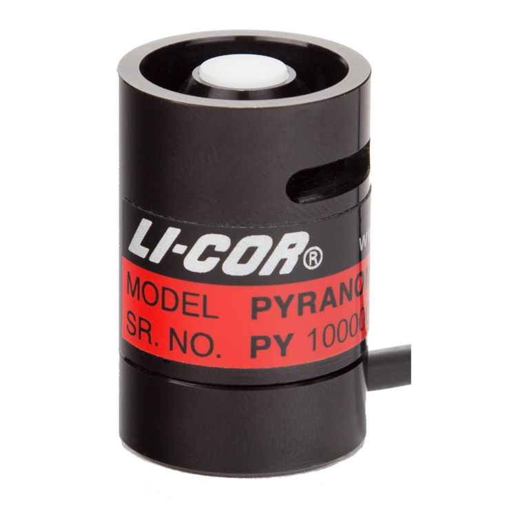
LI-COR LI-200R User manual
LI-COR
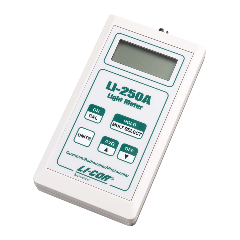
LI-COR LI-250A User manual

LI-COR
LI-COR TriSonica LI-560 User manual
LI-COR
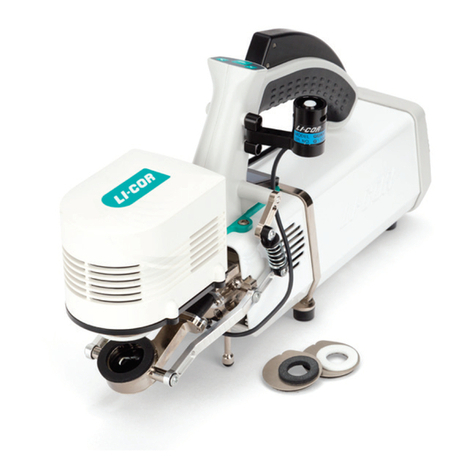
LI-COR LI-6800 User manual
LI-COR
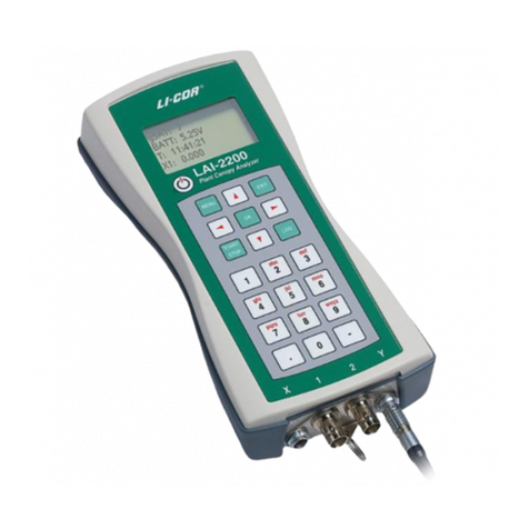
LI-COR LAI-2200 User manual

LI-COR
LI-COR Li-189 User manual
LI-COR
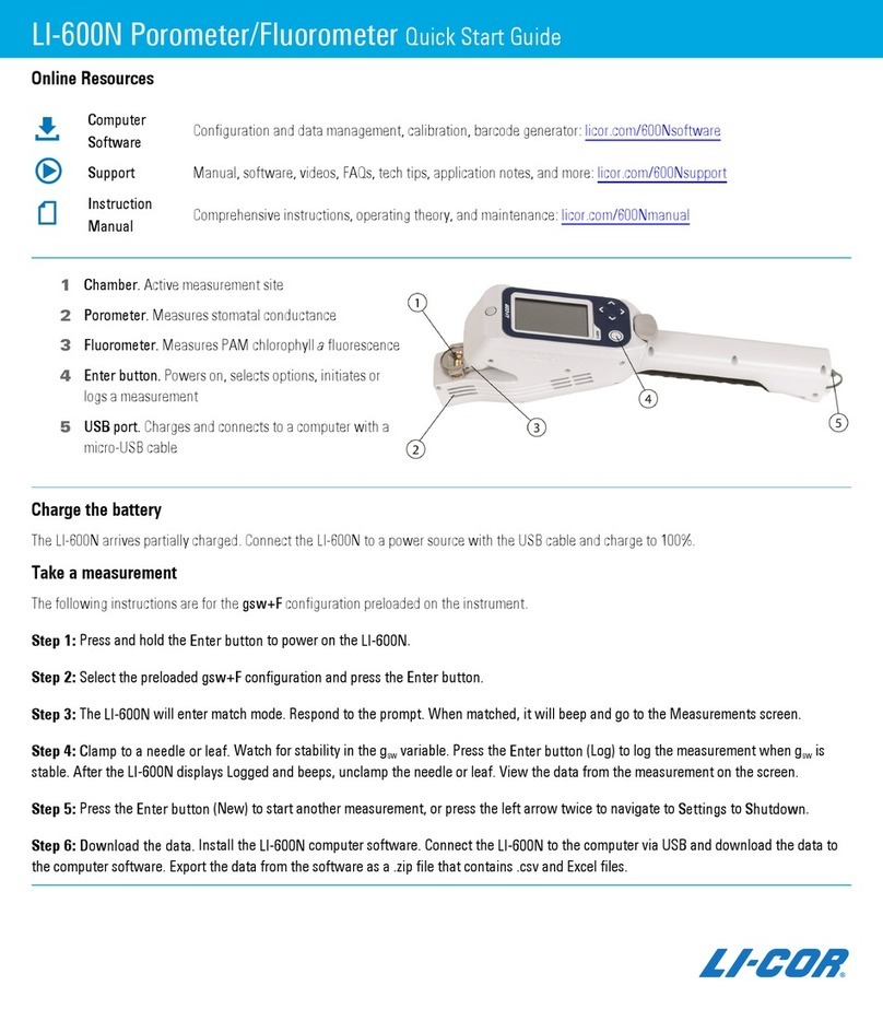
LI-COR LI-600N User manual

LI-COR
LI-COR LI-7500 User manual
LI-COR
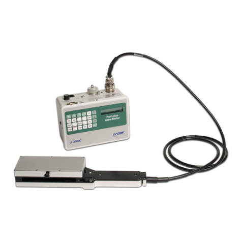
LI-COR LI-3000C Use and care manual

LI-COR
LI-COR LI-600 User manual

LI-COR
LI-COR LI-180 User manual

LI-COR
LI-COR LI-250 User manual

LI-COR
LI-COR LI-820 User manual
LI-COR
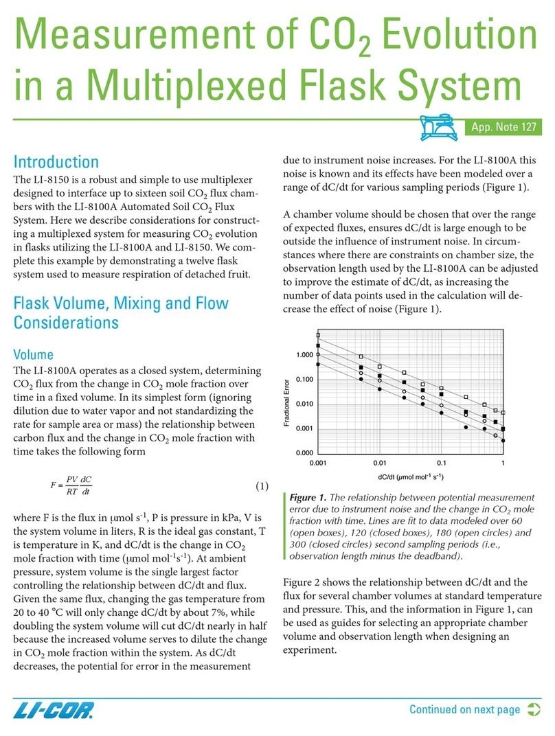
LI-COR LI-8150 Multiplexer Installation and operating instructions
LI-COR
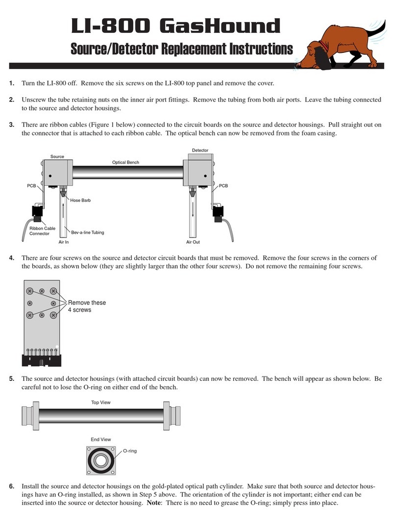
LI-COR LI-800 Guide
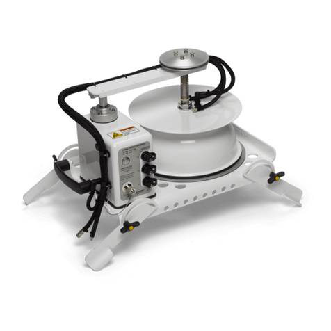
LI-COR
LI-COR LI-8100A User manual

LI-COR
LI-COR LI-250A User manual
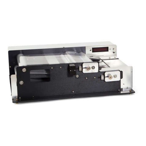
LI-COR
LI-COR LI-3100C User manual
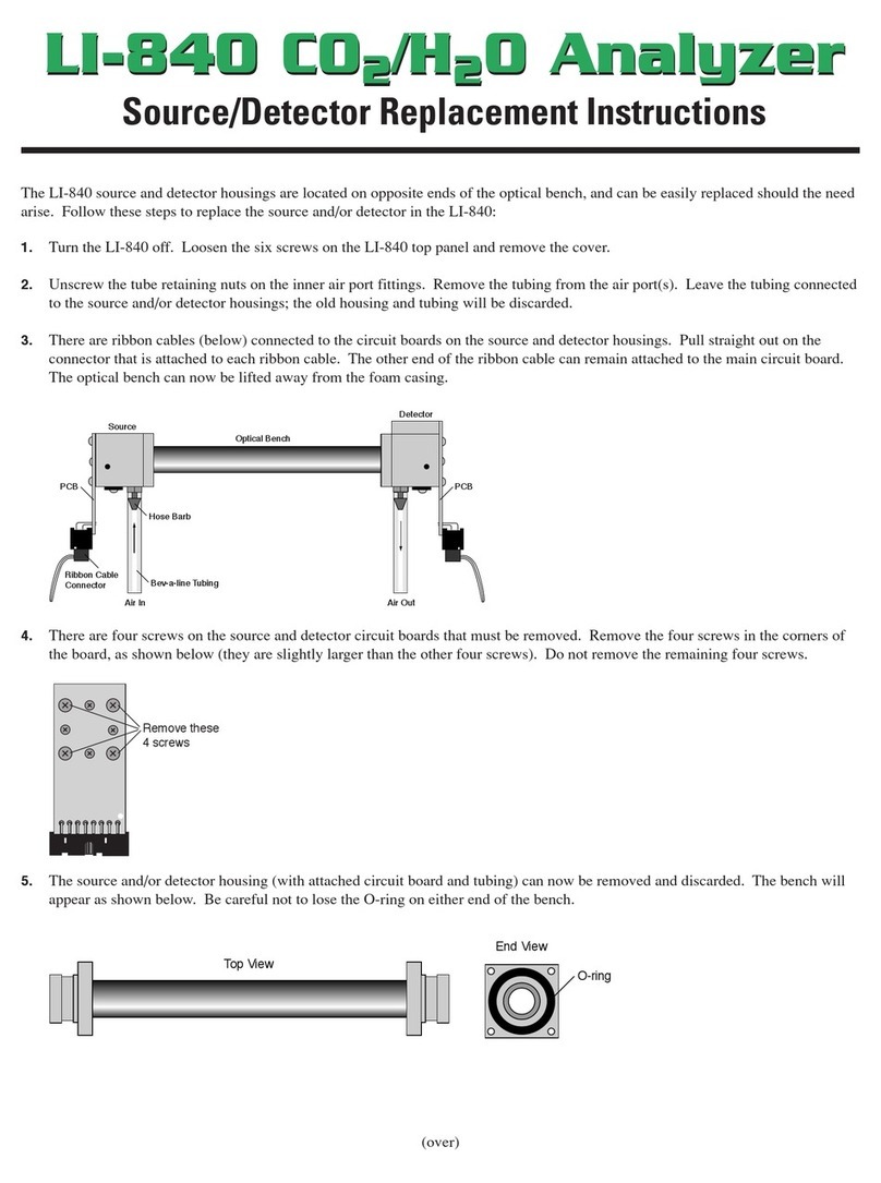
LI-COR
LI-COR LI-840 Guide

LI-COR
LI-COR LAI-2200 User manual
Popular Measuring Instrument manuals by other brands

Powerfix Profi
Powerfix Profi 278296 Operation and safety notes

Test Equipment Depot
Test Equipment Depot GVT-427B user manual

Fieldpiece
Fieldpiece ACH Operator's manual

FLYSURFER
FLYSURFER VIRON3 user manual

GMW
GMW TG uni 1 operating manual

Downeaster
Downeaster Wind & Weather Medallion Series instruction manual

Hanna Instruments
Hanna Instruments HI96725C instruction manual

Nokeval
Nokeval KMR260 quick guide

HOKUYO AUTOMATIC
HOKUYO AUTOMATIC UBG-05LN instruction manual

Fluke
Fluke 96000 Series Operator's manual

Test Products International
Test Products International SP565 user manual

General Sleep
General Sleep Zmachine Insight+ DT-200 Service manual
