manuals.online logo
Brands
  1. Home
  2. •
  3. Brands
  4. •
  5. LI-COR
  6. •
  7. Measuring Instrument
  8. •
  9. LI-COR LI-8100A User manual

LI-COR LI-8100A User manual

Replacing the Source and Detector in
the LI-8x0 Analyzers and LI-8100/A
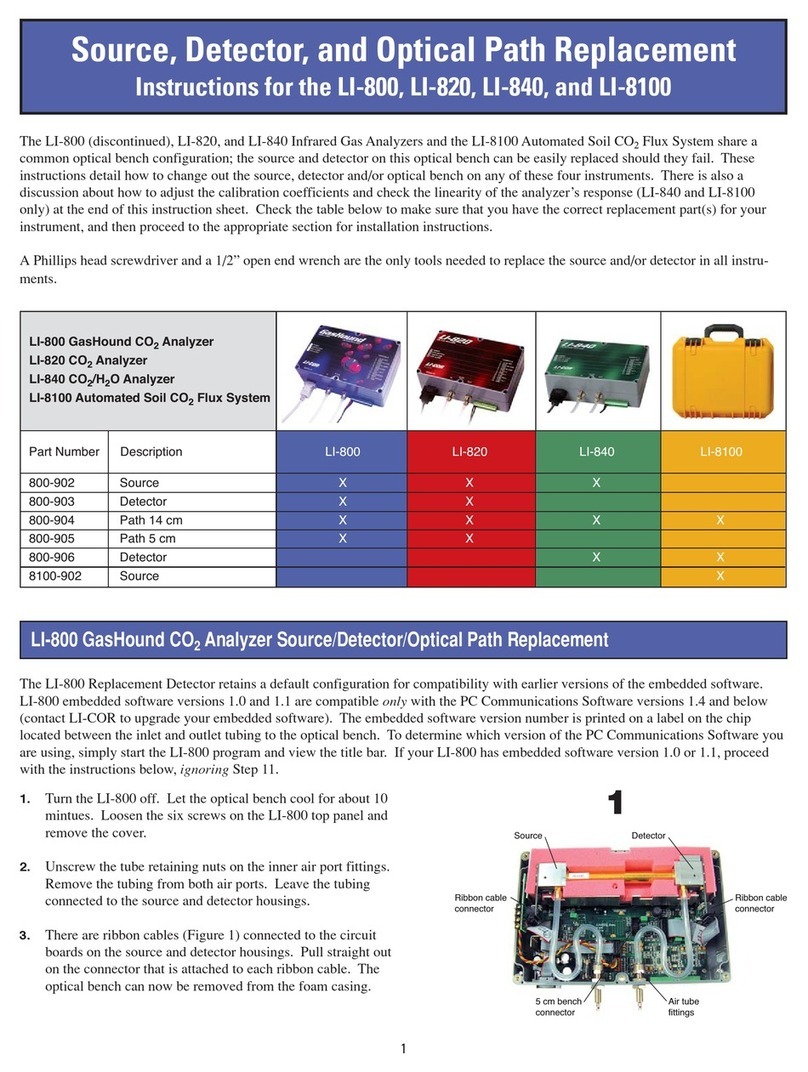
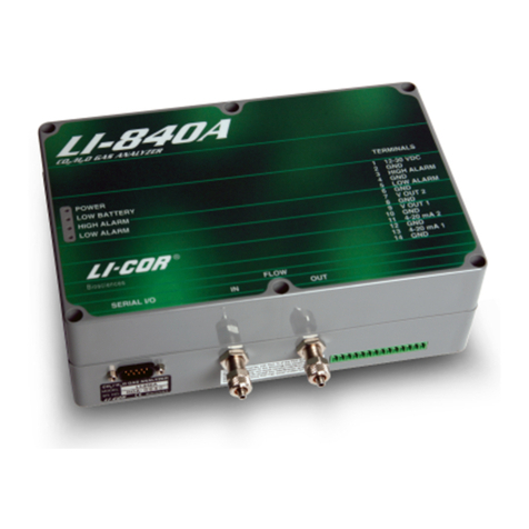
This document describes how to replace the optical source
and detector on the LI-830, LI-850, and LI-870 gas analyzers,
legacy LI-800, LI-820, LI-840, and LI-840A gas analyzers, and
the LI-8100/A Automated Soil CO2Flux System.
Part Numbers
Source Detector 14 cm
Bench
5 cm
Bench
LI-850 / LI-
870
800-902 800-918 800-904 n/a
LI-830 800-902 800-916 800-904 n/a
LI-840/A 800-902 800-906 800-904 n/a
LI-820 800-902 800-903 800-904 800-905
LI-800 800-902 800-903 800-904 800-905
LI-8100/A 8100-902 800-906 800-904 n/a
Contents
LI-800, LI-820, LI-830, LI-840/A, LI-850, and LI-870 1
LI-8100/A Source and Detector Replacement 3
LI-800, LI-820, LI-830, LI-840/A, LI-850,
and LI-870
The optical source and detector may need to be replaced if
one fails. The life expectancy of the source is typically
>20,000 hours, or >2 years of continuous operation, but this
will vary depending upon the number or warm-up cycles,
vibration, and other factors. Typically, detectors need to be
replaced rarely, if ever.
Disassembly
You'll need #1 or #2 Phillips screwdriver and a clippers or
utility knife. The installation, including calibration, may take
an experienced technician 30 minutes to 1 hour. If the instru-
ment has been running recently, the bench may be hot to the
touch. Let it cool for 5 or 10 minutes after powering off if
needed.
Note: Be sure that you are properly grounded to avoid elec-
trostatic discharge that can damage the electronics. Use an
anti-static wrist strap, electrostatic discharge grounding mat,
or occasionally touch bare metal that has a clear path to
ground, such as an unpainted computer case.
1Power off the gas analyzer and remove the top cover
(LI-800, LI-820, LI-830, LI-840/A and LI-850) or open
the case (LI-870 only).
The LI-800, LI-820, LI-830, LI-840/A and LI-850 top cover
is held in place by 6 screws. Loosen the screws and lift off
the cover. If there is a ribbon cable connecting the top
panel, be careful not to strain it. The LI-870 is opened by
removing two screws that hold the case closed; then
remove four screws that secure the optical bench cover.
2Unplug the source and detector ribbon cables from
the source and detector.
3Lift the optical bench out of the foam insulation.
Replacing the Optical Source
With the optical bench free of the case (except the tubing),
you can remove the source from the optical bench.
1Remove the tube from the source.
The simplest way is to cut the tubing as close to the hose
barb as possible.
2Remove the four larger screws from the optical
source.
1
Installation Guide
3Separate the source from the optical path.
Be sure that the inside of the optical path is clean—free of
dust and other contaminants. Clean it if needed, as
described in the instruction manual.
4Install the new O-ring that is included with the
source.
5Install the replacement optical source.
Tighten the screws firmly.
6Press the air-in tube over the hosebarb—be sure it
covers both barbs on the hosebarb.
Removing a section of tubing will reduce the total
volume of the analyzer, and this may affect some char-
acteristics of the analyzer, such as the T90 specification,
but the reduction in volume is generally negligible. There
is enough slack in the original tubing for a single replace-
ment of the source, but if you replace it more than once,
you may need to replace the entire segment of tubing.
Should you choose to recalculate system volume after
removing a segment of tubing (which is not required), the
Bev-A-Line® has an inside diameter of 1/8" (0.3175 cm).
If you removed 1 cm (0.39 inches) of tube, the volume
removed is about 0.079 cm3(π × r2× length; 3.14 ×
(0.3175 cm / 2)2× 1 cm = 0.079 cm3).
7Work the optical bench into the foam.
Be sure that the bench is secured tightly in the foam insu-
lation and that no parts are in direct contact with the sur-
rounding metal cradle.
8Connect the ribbon cables that were removed pre-
viously.
9Reassemble the instrument.
Make sure that the foam insulation on the inside top
cover is positioned over the optical bench; it is required
for thermal stability. Reconnect the top cover ribbon
cable and then install the top cover.
10 In the LI-830, LI-850, and LI-870, reset the source
hours to "0".
The LI-830, LI-850, and LI-870 record the number or oper-
ating hours for the optical source. You should reset this
count after replacing the source. Connect using the soft-
ware and then click Settings >Diagnostics and click the
gear button near Source, and then reset the hours.
11 Zero and span the analyzer as described in the instruc-
tion manual.
A simple zero and span will be adequate if the span gas is
close to the concentrations you will measure. A dual span,
however, will bring the instrument performance within
specifications across the full measurement range. If you
do not have zero and span gases, send the instrument
back to LI-COR for a factory recalibration.
Replacing the Optical Detector
You can also replace the optical detector.
1Remove the tube from the detector.
When replacing the detector on the LI-830, LI-850, or LI-
870, you will probably need to replace the entire segment
of urethane tubing, because cutting a portion to remove it
from the hose barb will not leave enough tubing to re-con-
nect using the original segment. A replacement segment
of urethane tubing is included in the detector replace-
ment kit for this purpose. On the LI-800, LI-820, or LI-
840/A, the tubing is long enough to reconnect.
2Remove the four screws that secure the optical
detector and shield.
2
On the LI-840/A, there are four spacers between the shield
and detector. Collect the four spacers.
3Separate the detector from the optical path.
Be sure that the inside of the optical path is clean. It
should be free of dust and other contaminants. Clean it if
needed, as described in the instruction manual.
4Install the new O-ring that is included with the
detector.
5Install the replacement optical detector.
On the LI-840/A, place the four spacers on the screws so
they fit between the shield and detector circuit board.
Tighten the screws firmly.
6Press the tube over the hosebarb—be sure it covers
both barbs on the hosebarb.
7Work the optical bench into the foam.
8Connect the wiring harnesses to the detector and
source.
9Reassemble the instrument.
Make sure that the foam insulation on the inside top
cover is positioned over the optical bench; it is required
for thermal stability. Reconnect the top cover ribbon
cable and then install the top cover.
Important: LI-840's that are running older software must
be updated to the latest LI-840A embedded software,
which is available for free from licor.com/env/support/LI-
840A/software.html.
10 Zero and span the analyzer as described in the instruc-
tion manual.
A simple zero and span will be adequate if the span gas is
close to the concentrations you will measure. A dual span,
however, will bring the instrument performance within
specifications across the full measurement range. If you
do not have zero and span gases, send the instrument
back to LI-COR for a factory recalibration.
LI-8100/A Source and Detector
Replacement
The LI-8100A Soil Gas Flux System the source and detector
on this optical bench can be replaced if they fail. These
instructions describe how to change the source, detector
and/or optical bench. A Phillips head screwdriver and a 1/2”
open end wrench are the only tools needed to replace the
source and/or detector in all instruments. To replace the
source or detector:
Component Part Number
Source 8100-902
Detector 800-906
Optical Bench 800-904
Note: Be sure that you are properly grounded to avoid elec-
trostatic discharge that can damage the electronics. Use an
anti-static wrist strap, electrostatic discharge grounding
mat, or occasionally touch bare metal that has a clear path
to ground, such as an unpainted computer case.
1Power the instrument off and remove the battery or
other external power source.
Allow the instrument optical bench to cool for about 10
minutes.
2Open the Analyzer Control Unit and remove the
access panel by loosening the 4 thumbscrews.
3Remove both air filters by pressing the orange part of
the quick-connect fittings toward the white part of
the connector and pulling the filter out.
Discard the filters. There are replacement filters included
that can be used during reassembly.
3
4Disconnect the 3 electrical connectors.
Two of them are on a single wiring harness, just to the
right of filter connectors; the third is at the left end of the
bundle of blue cables. Pull straight out on the connectors
to remove them.
5Remove the 5 screws from the top of the air man-
ifold.
The top half of the manifold rests on two pins; lift the top
half until it is completely separated from the bottom half.
It is not necessary to remove any of the hoses.
6Remove the 12 screws around the outer edge of the
white panel.
7Lift the assembly out of the yellow case and turn it
upside down.
8Remove the 6 screws from the optical bench cover.
9Leaving the hoses connected to the optical bench, lift
the bench out of the foam casing.
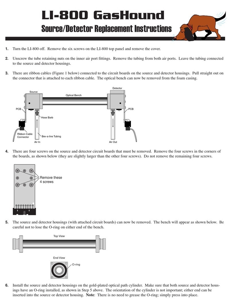
10 There are four screws on the source and detector
housings that must be removed.
Remove only the screws from the assembly you are repla-
cing. Remove the four screws in the corners of the source
housing circuit board. Do not remove the remaining four
screws. Remove the four screws from the detector housing
cover. Note that there are some small standoffs inserted
over the screws behind the cover; tilt the housing down
when removing the cover so these standoffs don’t get lost.
4
11 Disconnect the ribbon cable connectors attached to
the source and/or detector housing circuit board.
12 Remove the Bev-A-Line® tubing connected to the
source and/ or detector housing at the quick-connect
fitting.
Press down on the orange part of the fitting to remove
the tubing.
13 The source and/or detector housing, with the
attached circuit board and tubing can now be
removed and discarded.
Note that there are O-rings on each end of the optical
bench. It is a good practice to replace the O-ring when
replacing the source. Make sure the optical path tube is
clean (no dust, dirt, etc.) before proceeding. Clean it if
needed, as described in the instruction manual.
14 Re-assemble the bench using the replacement source
and/or detector.
Be sure the O-rings are in place on both ends of the
bench. Note that the orientation of the optical bench cyl-
inder is not important; either end can be inserted into the
source or detector housing.
15 Replace the tubing.
Any tubing that you removed should be replaced with a
piece of equal length, which can be cut from the tubing
that is included in the instrument spares kit.
16 Re-assemble the LI-8100/A case.
Make sure that the foam insulation on the inside top
cover is positioned over the optical bench; it is required
for thermal stability. The remaining assembly procedures
are the opposite of the disassembly.
17 Perform zero and span calibrations as described in
the LI-8100/A Instruction Manual.
A simple zero and span will be adequate if the span gas is
close to the concentrations you will measure. A dual span,
however, will bring the instrument performance within
specifications across the full measurement range. If you
do not have zero and span gases, send the instrument
back to LI-COR for a factory recalibration.
5
6
7
Copyright © 2022 LI-COR, Inc. All rights reserved.
984-17308•06/2022
LI-COR Biosciences
4647 Superior Street
Lincoln, Nebraska 68504
Phone: +1-402-467-3576
Toll free: 800-447-3576 (U.S. and Canada)
[email protected]
LI-COR Distributor Network:
www.licor.com/envdistributors
Regional Offices
LI-COR Biosciences GmbH
Siemensstraße 25A
61352 Bad Homburg
Germany
Phone: +49 (0) 6172 17 17 771
[email protected]
LI-COR Biosciences UK Ltd.
St. John’s Innovation Centre
Cowley Road
Cambridge
CB4 0WS
United Kingdom
Phone: +44 (0) 1223 422102
[email protected]

Other manuals for LI-8100A

3

This manual suits for next models

7

Other LI-COR Measuring Instrument manuals

LI-COR LI-7500 User manual

LI-COR

LI-COR LI-7500 User manual

LI-COR LI-820 User manual

LI-COR

LI-COR LI-820 User manual

LI-COR LI-7820 User manual

LI-COR

LI-COR LI-7820 User manual

LI-COR TriSonica LI-560 User manual

LI-COR

LI-COR TriSonica LI-560 User manual

LI-COR LI-7810 User manual

LI-COR

LI-COR LI-7810 User manual

LI-COR LI-8100 User manual

LI-COR

LI-COR LI-8100 User manual

LI-COR LI-840/A User manual

LI-COR

LI-COR LI-840/A User manual

LI-COR LAI-2200 User manual

LI-COR

LI-COR LAI-2200 User manual

LI-COR LI-820 User manual

LI-COR

LI-COR LI-820 User manual

LI-COR LI-3000C User manual

LI-COR

LI-COR LI-3000C User manual

LI-COR LI-830 User manual

LI-COR

LI-COR LI-830 User manual

LI-COR LI-800 User manual

LI-COR

LI-COR LI-800 User manual

LI-COR LI-3100C User manual

LI-COR

LI-COR LI-3100C User manual

LI-COR li-6262 User manual

LI-COR

LI-COR li-6262 User manual

LI-COR LI-600N User manual

LI-COR

LI-COR LI-600N User manual

LI-COR LAI-2000 How to use

LI-COR

LI-COR LAI-2000 How to use

LI-COR LI-3000C Use and care manual

LI-COR

LI-COR LI-3000C Use and care manual

LI-COR LI-8100A User manual

LI-COR

LI-COR LI-8100A User manual

LI-COR LI-870 Guide

LI-COR

LI-COR LI-870 Guide

LI-COR LI-830 Guide

LI-COR

LI-COR LI-830 Guide

LI-COR LI-800 Guide

LI-COR

LI-COR LI-800 Guide

LI-COR li-7200 User manual

LI-COR

LI-COR li-7200 User manual

LI-COR LI-180 User manual

LI-COR

LI-COR LI-180 User manual

LI-COR LI-250 User manual

LI-COR

LI-COR LI-250 User manual

Popular Measuring Instrument manuals by other brands

PROF PROFS7-60M instruction manual

PROF

PROF PROFS7-60M instruction manual

Memsense Nano IMU Product Specification & User Guide

Memsense

Memsense Nano IMU Product Specification & User Guide

KROHNE LEVEL-SONIC BM90 Series Installation and operating instructions

KROHNE

KROHNE LEVEL-SONIC BM90 Series Installation and operating instructions

LIMIT 7000 operating manual

LIMIT

LIMIT 7000 operating manual

Netatmo Smart Anemometer manual

Netatmo

Netatmo Smart Anemometer manual

DATEREMOTE CDS-9020 manual

DATEREMOTE

DATEREMOTE CDS-9020 manual

Sensaphone WEB600 user manual

Sensaphone

Sensaphone WEB600 user manual

Mi LYWSD03MMC user manual

Mi

Mi LYWSD03MMC user manual

PeakTech 1650 Operation manual

PeakTech

PeakTech 1650 Operation manual

Omega DP3001 user guide

Omega

Omega DP3001 user guide

PSI LaiPen LP 110 Instruction guide

PSI

PSI LaiPen LP 110 Instruction guide

TOOLCRAFT 81 58 17 operating instructions

TOOLCRAFT

TOOLCRAFT 81 58 17 operating instructions

LAPP ETHERLINE GUARD PM03T quick start guide

LAPP

LAPP ETHERLINE GUARD PM03T quick start guide

Ballenger Motorsports AFR500v2 Tuning Manual

Ballenger Motorsports

Ballenger Motorsports AFR500v2 Tuning Manual

AND AD-4532B instruction manual

AND

AND AD-4532B instruction manual

Schwarzkopf SALON LAB manual

Schwarzkopf

Schwarzkopf SALON LAB manual

Topcon CL-200 instruction manual

Topcon

Topcon CL-200 instruction manual

LaserLiner MeterMaster Plus quick start guide

LaserLiner

LaserLiner MeterMaster Plus quick start guide

manuals.online logo
manuals.online logoBrands
  • About & Mission
  • Contact us
  • Privacy Policy
  • Terms and Conditions

Copyright 2025 Manuals.Online. All Rights Reserved.