Life PROBO PR70 Parts list manual

LC020508 - LIFE - 10/2008
PROBO PR70 PR70-DL
PR120 PR120-DL
MOTORIDUTTORE ELETTROMECCANICO IRREVERSIBILE PER PORTE SEZIONALI E BASCULANTI
ISTRUZIONI E AVVERTENZE PER L’INSTALLAZIONE, L’USO E LA MANUTENZIONE.
IRREVERSIBLE ELECTRO-MECHANICAL OPERATOR FOR SECTIONAL AND UP-AND-OVER DOORS
INSTRUCTIONS AND INDICATIONS FOR INSTALLATION, USE AND MAINTENANCE.
M
OTO-REDUCTEUR ELECTROMECANIQUE IRREVERSIBILE POUR PORTES SECTIONNELLES ET BASCULANTES
INSTRUCTIONS ET CONSEILS POUR L’INSTALLATION, L’EMPLOI ET L’ENTRETIEN.
M
OTORREDUCTOR ELECTROMECÁNICO IRREVERSIBLE PARA PUERTAS SECCIONALES Y BASCULANTES
INSTRUCCIONES Y ADVERTENCIAS PARA LA INSTALACIÓN, EL USO Y EL MANTENIMIENTO.
CENTRAIS DE COMANDO PARA PORTÕES DE BATENTE
INSTRUÇÕES E ADVERTÊNCIAS PARA A INSTALAÇÃO, USO E MANUTENÇÃO.
ELEKTROMECHANISCHER TORANTRIEB PROBO FÜR SCHWING- UND GARAGENTORE
ANLEITUNGEN UND HINWEISE FÜR INSTALLATION, GEBRAUCH UND WARTUNG.
M
OTOREDUKTOR ELEKTROMECHANICZNY NIEZWROTNY DO BRAM SEKCYJNYCH I WAHADŁOWYCH
INSTRUKCJE I WSKAZÓWKI DOTYCZĄCE MONTAŻU, UŻYTKOWANIA I KONSERWACJI.
Н
ЕРЕВЕРСИВНЫЙ ЭЛЕКТРОМЕХАНИЧЕСКИЙ ПОТОЛОЧНЫЙ ПРИВОД ДЛЯ СЕКЦИОННЫХ И
ПОДЪЕМНО-ПОВОРОТНЫХ ВОРОТ
ИНСТРУКЦИИ, ЗАМЕЧАНИЯ ПО МОНТАЖУ, ЭКСПЛУАТАЦИИ И ТЕХНИЧЕСКОМУ ОБСЛУЖИВАНИЮ.
E
LEKTROMECHANICKÝ NEREVERZNÝ POHON PROBO PRE SEKČNÉ A VÝKLOPNÉ GARÁŽOVÉ BRÁNY
UPOZORNENIA A NÁVOD NA INŠTALÁCIU, POUŽÍVANIE A ÚDRŽBU.
VEZÉRLŐEGYSÉG 24 V-OS MOTOROKHOZ
SZERELÉSI UTASÍTÁSOK ÉS FIGYELMEZTETÉSEK, HASZNÁLAT ÉS KARBANTARTÁS.
ŘÍDÍCÍ JEDNOTKA POHONU PRO AUTOMATIZACI VYBAVENOU 24 V MOTORY
POKYNY A VAROVÁNÍ PRO INSTALACI, POUŽITÍ A ÚDRŽBU.

1 A
Tab.2: componenti e dispositivi di un’automazione tipo, vedi figura.
Тав.1: Компоненты и устройство автоматики типа,
см. рис.
Tab.1: componenti e dispositivi di un’automazione tipo, vedi figura.
Тав.1: Компоненты и устройство автоматики типа, см. рис.
ACER
Manuale di istruzioni
ACER
Manuale di istruzioni
PROBO
INSTALLAZIONE STANDARD
STANDARD INSTALLATION
INSTALLATION STANDARD
INSTALACIÓN ESTÁNDAR
ŠTANDARTNÁ INŠTALÁCIA
ÁLTALÁNOS TELEPÍTÉS
STANDARTNÍ INSTALACE
INSTALAÇÃO STANDARD
STANDARDINSTALLATION
INSTALACJA STANDARDOWA
СТАНДАРТНАЯ УСТАНОВКА

2 A
10 11
15
13
4
16 17
89
7
6
14
5
2
1
3
1
12
DESCRIZIONE PARTICOLARI
SPECIFIC DESCRIPTION
DESCRIPTION SPECIFIQUE
DESCRIPCIONES PARTICULARES
ŠTANDARTNÁ INŠTALÁCIA
ÁLTALÁNOS TELEPÍTÉS
STANDARTNÍ INSTALACE
DESCRIÇÕES PRELIMINARES
OPIS ELEMENTÓW
BESCHREIBUNG DERBESTANDTEILEN
ОПИСАНИЕ ОСОБЕННОСТЕЙ

HSILGNE
MANUAL DESTINED TO PROFESSIONAL FITTERS ONLY
Under applicable law, installation may only be performed by professional tters.
1 TECHNICAL DATA
LIFE home integration reserves the right to vary technical features at any time and without giving prior notice, whilst maintaining the same intended usage and functions.
PROBO is a family of irreversible electromechanical operators for the automation of residential type sectional and up-and-over doors. The range is
constituted by two different power models. PR70-07 / PR70-DL e PR120-07 / PR12 DL. Motion transmission is performed through chain or belt-driven
retainer runners; the retainer runner is equipped with a release mechanism in order to make it possible to move the door manually in the event of need.
Irreversible electro-mechanical operator for sectional and up-and-over door with
built in encoder and electronic unit.
MODELS
PROBO
230 Vac 50 HzMains power supply
24 V dcMotor power supply
greaseLubrication
noElectromechanical end stops
yesEncoder
50Work cycles
13Nominal work time
15Courtesy light 24 Vdc (internal)
from -20 to +70Operating temp.
Horizontal ceiling-mounted on dedicated runnerAssembly
442x213x142 (h) mm / 6.7 KgDimensions / weight
noUse in acid, saline or potentially explosive environment
20Protection class
FMotor insulation class
Speed
Max. power
Max. input
Input power to line (230V)
Thrust
Max. leaf surface area*
PR70-07 / PR 70-DL
0,10 - 0,18
260
8,5
1,2
650
11.5
RG1 24P / RG1 24 DL
V
V
Type
%
min
W (max.)
°C
IP
m/s
W
A
A
N
Control unit
0,08 - 0,12
310
10
1,3
1100
18
RG1 24P / RG1 24 DL
PR120-07 / PR 120-DL
Fig.1
2 INSTALLATION
2.1 Preliminary checks and usage restrictions
Before commencing installation, the following preliminary checks must be performed:
a) The area in which the automation is installed must provide adequate space for performing maintenance and manual release operations. Check the
total dimensions by referring to g. 1, and the manuale provided.
b) T
he automation may be installed on both sectional and up-and-over doors; for up-and-over doors it is necessary to use the oscillating, curved arm APRB
The value given in Tab. is intended as a rough guide as many factors dictate the limits of use and they must be considered carefully for each installation.
The maximum height of the door to be automated
depends on the length of the runner used, which is
provided separately from the operator.
* Values reported to gates perfectly balanced.
442
143 213
PR70-07 / PR70-DL
PR120-07 / PR120-DL
5Maximum door width (m)* 6.5
1

2
2.2 Installing operator components
2.2.1 Mounting the operator on the runner
a) Open the operator hatch (1) and loosen the clamping screws (2).
b) Then remove the cap (3) from the base, paying attention to the rear tting of the
cover (4) with the base.
c) Remove the omega-shaped support brackets (5) by unscrewing the 4 screws (6)
that fasten them to the base (7).
d) M
ount the operator on the runner, introducing the protruding shaft of the operator (8)
into the hole on the block (9), taking care not to force the tab.
e) F
asten the operator to the runner using the omega-shaped support brackets (5), fastening
i
t with the four hexagonal-headed screws (6) provided with the operator base (7).
2.2.2 Automation installation
ATTENTION: the automation may only be installed once the various parts of the runner have been installed and the operator has been installed on the runner.
Sectional door:
a) T
he minimum vertical distance of the sectional door from the ceiling Ais 40 mm. If the distance exceeds the height of the brackets adequate spacers
must be used.
b) The vertical distance of the sectional door from the operator runner Bmust be between 10 and 65 mm.
c) Close the door and measure out the centre point, marking it on the door and on the wall/ceiling.
d) A
t a distance of 73 mm to the left and right of the centre, mark the centre of the xing holes of the front runner brackets, then drill the holes and insert
the screw anchors.
6
5
7
9
8
7
5
1
3
6
4
2
BA
40 mm
10 :100 mm
73mm
73mm

HSILGNE
3
e) Lift the front part of the runner leaving the operator resting on the oor and rmly x the front brackets onto the screw anchors arranged previously
using suitable screws and washers.
f) Completely lift the runner with the operator and position it ensuring that it is parallel to the ceiling.
g) Adjust the position of the rear brackets (8) so that they rest well on the ceiling, then mark the centres for the xing holes.
h) Drill the holes, insert the screw anchors and rmly fasten the two rear brackets (8) to the ceiling using suitable screws and washers.
i) Ensure that the runner is perfectly aligned and level; if necessary adjust the position in relation to the rear brackets.
j) Lock all the front and rear bracket clamping screws.
k) Release the drive trolley (9) by pulling the cord and take it forward to allow the installation
of the drive bracket (10) on the sectional door.
l) P
osition the drive bracket (10) on the upper edge of the sectional door and fasten using
suitable screws or rivets.
m) C
onnect the drive bracket (10) to the thrust arm (11) using the screws and self-locking
nut provided.
ATTENTION: in order for the mechanism to work properly the angle between the runner (12)
and the thrust arm (10) must not be greater than 30°.
n) R
elease the operator and manually perform a number of opening and closure manoeuvres
i
n order to verify that it is correctly balanced: the manoeuvres must be performed with ease
and the door must move without catching or swinging.
Up and over door:
The APRB curved oscillating arm is required, refer to the instruction manual provided.
8
10
0
11

4
2.2.3 Operator release
ATTENTION:
• The tter must permanently x the label describing the manual release operation close to the manual release lever.
• T
he activation of the manual release could cause an uncontrolled movement of the door in the event of mechanical damage or unbalanced conditions.
• Before performing the manoeuvre switch off the electricity supply to the automation.
This command is used in the event of a blackout or system faults, to release the operator transmission and allow manual moving of the sectional/up-
and-over door.
a) Pull the cord connected to the mobile trolley (1) and move the door manually.
b) The door is now free and can be moved by hand.
c) To reconnect the transmission take the door to the initial position until it hooks back up.
ATTENTION: for garages that do not have a second access, the ASEC PR device for manual release from outside must be installed
3 WIRING AND CONNECTIONS
• The operator may only be connected to a suitable control unit manufactured by Life.
• A
ll wiring and connection operations must be carried out with the operator disconnected from the electricity supply; if the disconnection device is not
n view, display a sign reading “ATTENTION: MAINTENANCE WORK IN PROGRESS”.
The internal operator wiring performed by the Manufacturer, may not be modied under any circumstances.
This manual does not describe how the electrics system should be prepared for connection to the mains however it gives the following warnings:
• The electricity power line must be installed and connected by a qualied technician or professional tter.
• The electricity supply line must have adequate protection against short circuits and must be earthed.
• The power supply network must contain a unipolar disconnection device with an opening distance of the contacts equal or greater than
3.5 mm that assures the complete disconnection of the power supply.
3.1 Introducing the electric wires into the operator
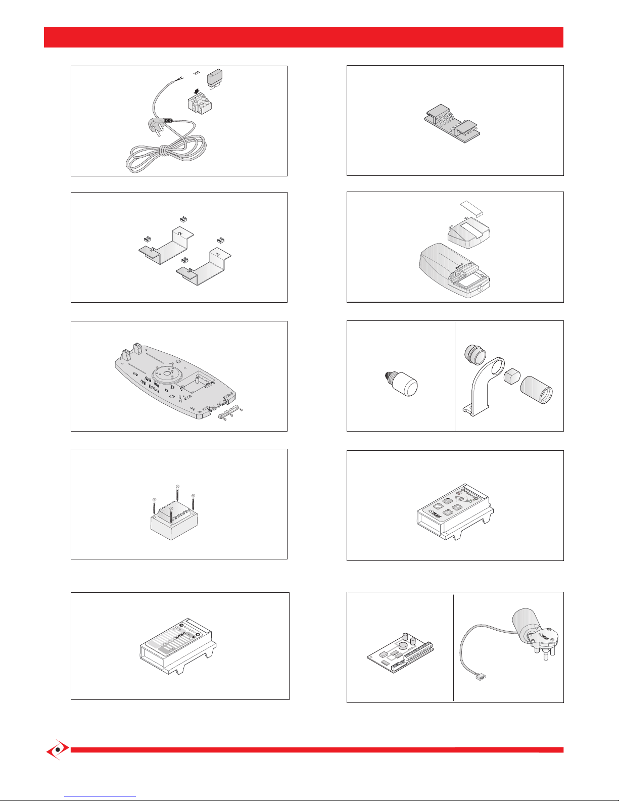
a) To access the terminals in the control unit, remove the cap (1) that covers the operator.
b) Open the operator hatch (2) and loosen the clamping screws (3).
c) Then remove the cap (1) from the base, paying attention to the rear tting of the cover (4) with the base.
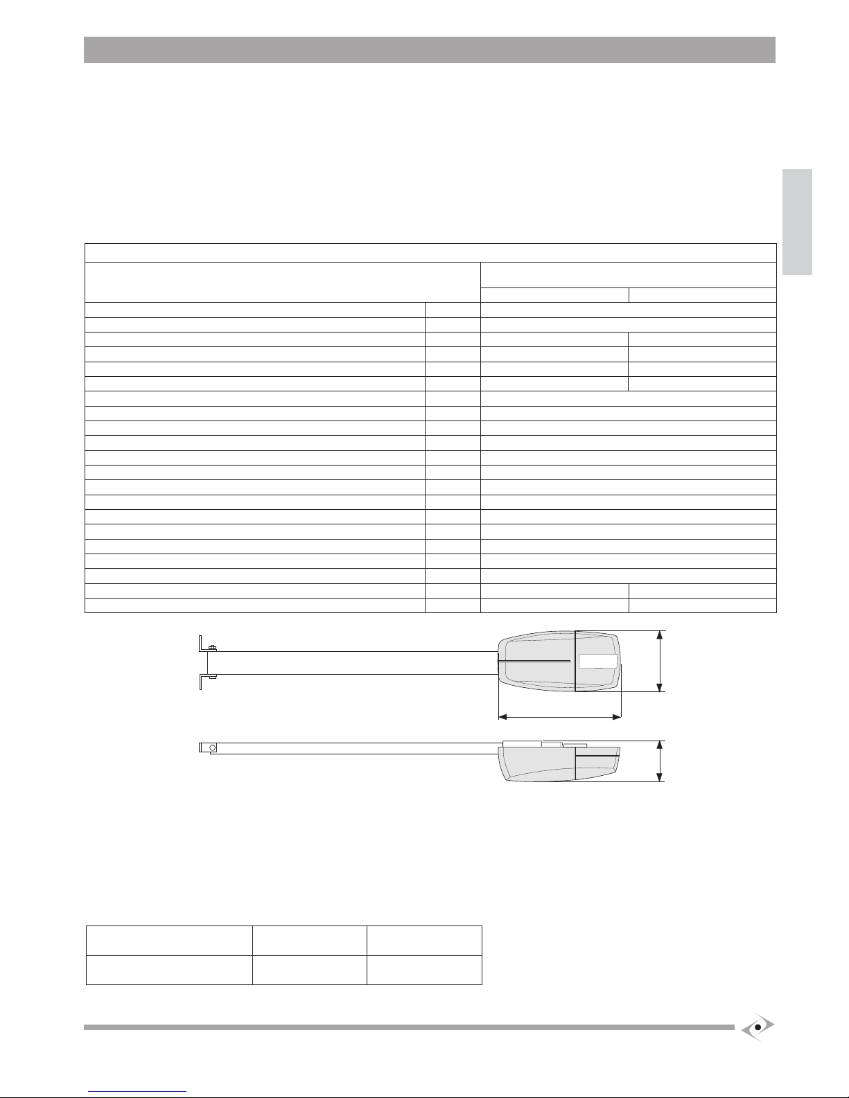
d) Loosen the screws (5) that fastens the cable gland (6) to the base and remove it.
e) The cables must be inserted through the corresponding holes on the base (7): keep the 230V cables separate from the very low voltage ones.
f) Leave the cables about 40cm longer.
g) Fasten the cables to the base using the assembly of the cable gland (6).
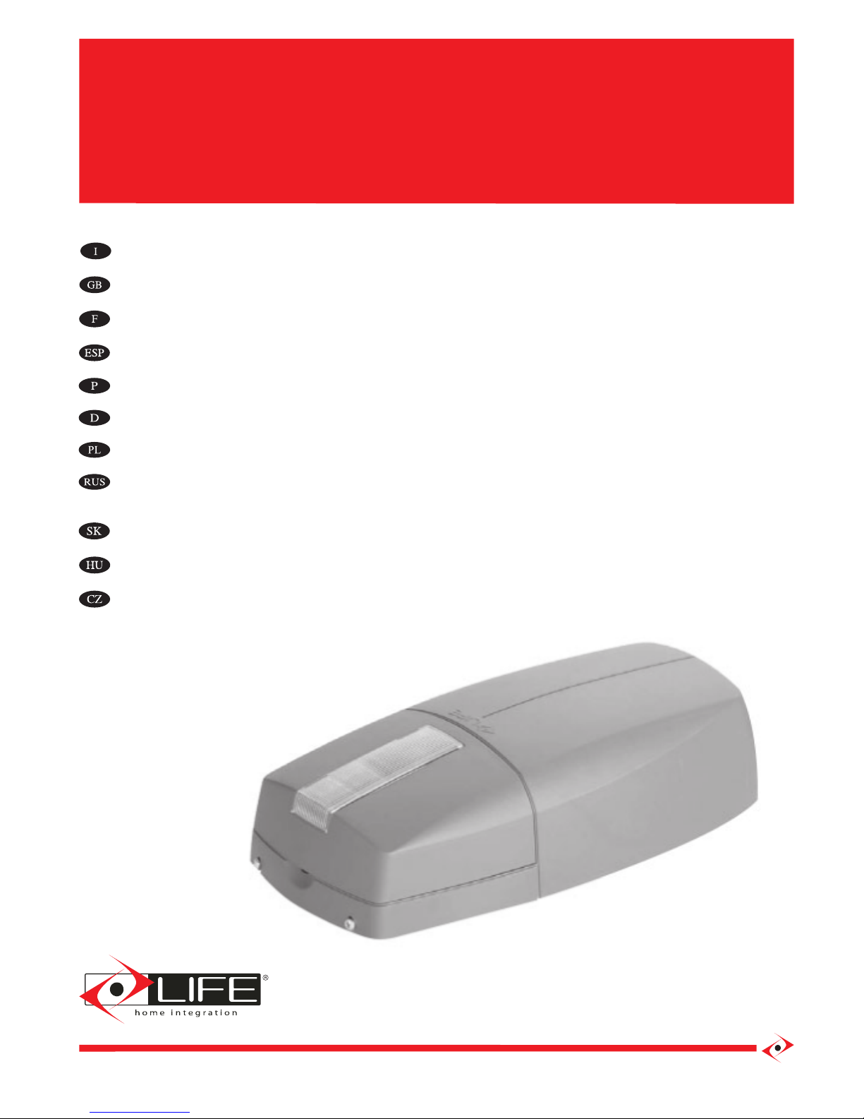
For connection to a 230 V ac 50 Hz power supply, use the power cable with ready-wired schuko plug provided with the operator only (8).
Do not modify the connections between the power cable (7), transformer (8) and control unit (9).
The power cable provided may not be extended or shortened.
1
1
Cable length
max 40 mm
5
6
7
4
1
2
3
8
9
10

HSILGNE
5
Declaration of conformity
under Directive 98/37/EC, appendix II, part B (Manufacturer’s Declaration of CE Conformity)
LIFE Home Integration
Via 1 Maggio, 37
31043 FONTANELLE (TV) – Italy
declares that the following product:
PROBO PR70 PR70-DL PR120 PR120-DL
satisfies the essential requisites established in the following directives:
• Low voltage directive 73/23/EEC and subsequent amendments,
• Electromagnetic compatibility directive 89/336/EEC and subsequent amendments,
• Radio and telecommunications equipment directive 1999/5/EC and subsequent amendments.
and satisfies the following standards:
• EN 12445:2000
Industrial, commercial and garage doors and gates – Safety in the usage of motorised doors –
testing methods
• EN 12453:
Industrial, commercial and garage doors and gates – Safety in the usage of motorised doors –
Requisites
• EN 60204-1:1997 Machinery safety – Electric equipment of the machine – Part 1: general rules.
The Manufacturer also declares that it is not permitted for the abovementioned components to be used until such time as the
system in which they are incorporated is declared conform to directive 98/37/EC.
Fontanelle 20/10/2007 Name of Signor: Faustino Lucchetta
Position: Managing Director
Signature: __________________

15RI15800 25RI11100
35RI11200 45RI11300
55RI11400 65RI20000 75RI11500
8 5RI18500 PR70 9 5RI18600 PR120
10 5RI28400 PR70 DL 11 5RI28500 PR120 DL
14 5RI01900
12 5RI01900 16 5RI11600 PR70
17 5RI11700 PR120
13 1AH00900 PR70-PR120
17 5RI38300 PR70 DL-PR120 DL
3 A

Address:
Via I Maggio, 37 - 31043 FONTANELLE (TV) Italia
Telephone: + 39 0422 809 254
Telefax: + 39 0422 809 250
http www.homelife.it
e-mail: [email protected]
Numero Verde
800-046826
15RI15800 25RI11100
35RI11200 45RI11300
55RI11400 65RI20000 75RI11500
8 5RI18500 PR70 9 5RI18600 PR120
10 5RI28400 PR70 DL 11 5RI28500 PR120 DL
14 5RI01900
12 5RI01900 16 5RI11600 PR70
17 5RI11700 PR120
13 1AH00900 PR70-PR120
17 5RI38300 PR70 DL-PR120 DL
This manual suits for next models
3
Table of contents
Other Life Gate Opener manuals