Check that quote “C” on the support structure of the gate does not exceed value shown on g. 3. If value exceeds, proceed with a reentry in the
structure until reaching the value shown on gure. This is needed to avoid that the linear operator hits the edge of the structure in closure. The reentry
must be done where the linear operator will be installed, and have a height to allow the passage of the operator.
g. OP2005 showsthe set up measurements for the operator installation:
Table.3 showsAand Bvalues recommended for a 90° leaf opening (angle α).
Table. 3: operator installation measurements
Opening A B C max D
mm mm mm mm
90° 160 160 70 630
We recommend not to chose A & B values too different one another, in order to garantee a regular leaf movement and a minimum stress on the
operator;
Measurement A: if increased, the opening angle increases too, and so force on the leaf decreases, and opening/closing speed increases.
Measurement B: if increased, the opening angle decreases, and so force on the leaf increases, and opening/closing speed decreases.
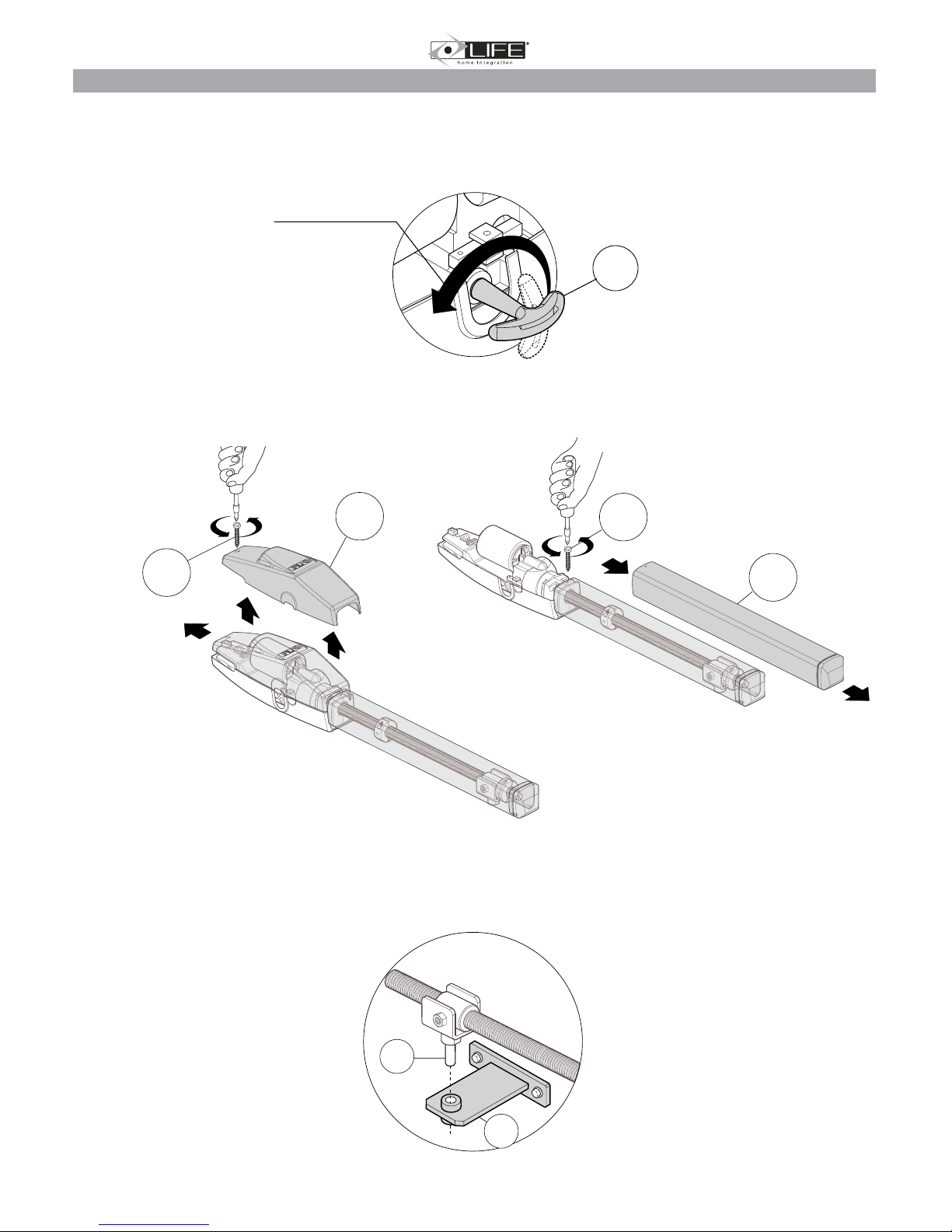
Rear bracket position
a) Dene the position of the rear bracket , See table 3 above for A, B & C measurements
b) Check the exit of the electric wires tube position to be under the bracket (3).
c) Check sufcient space for the xing (screws or welding) of the front bracket to the leaf.
d) Check the rear bracket is horizontal before fixing
e) Fix (with screws or welding) to the pillar in the desired position.
f) Take the leafs to the closed position against the mechanical stop
g) Bring the front bracket (1) to distance D (630mm) from the rear bracket
h) Position the front bracket (1) 54mm lower than the rear bracket (distance E)
i) Temporarily clamp the front bracket (1) to the gate in the correct position
j) Check the bracket is horizontal before fixing in place (4)
OP2005
1
4
2
13
D
E
2
3
4
1
35
�
D
A
B
D
C
�
�
1
2
ENGLISH
2MANUALE (INGLESE) Life.indd 3 30-10-2008 15:17:04
Check that the distance “C” on the gate support structure is no greater than the value given in the table below. If the distance is higher than this value,
it is necessary to intervene by making a niche in the structure to obtain the indicated value. This is to avoid the linear operator colliding with the edge of
the structure during closure. The niche must be made in the area in which the linear operator is to be installed and it must have a height such as to allow
operator passage.
2.3 Rear and front bracket positioning
a) Dene the clamping position of the rear bracket (1) of the operator, observing
the distances A, B and C.
b) Check that the outlet of the pipe housing the electric cables is below the
bracket (1).
c) Check that there is enough space on the leaf, at the point in which the operator’s
front bracket is to be clamped, and that the surface is suitable for clamping (with
screws or by means of welding).
d) Fix (with screws or by means of welding) the rear bracket (1) to the pillar in the
established position.
e) Make sure that the rear bracket (1) is perfectly level.
a. Take the leaf to the closure position, resting it against
the closure stop plates.
b. Position the front bracket (2) at distance E from the rear
bracket (1) and 68 mm lower.
The value of E must be just lower (10 mm) than D (maximum space between centres) to allow optimal stop plate adjustment.
a) Temporarily block the front bracket (2) with a clamp.
b) Check that the bracket is level using a spirit level.
OP324 UNI OP524 UN
Ω
OP3 - OP3L - OP3 UNI – OP3L UNI – OP324 OP5 – OP5L – OP5UNI – OP5L UNI – OP524
A -mm B -mm CMAXmm D*mm A -mm B -mm CMAXmm D*mm
Ω1=90° 140 140 90 max 755 210 210 140 max 905
Ω2=120° 140 100 50 max 755 210 120 70 max 905
1
1
1
2
2
EOP3= 745
EOP5= 895
68
1
A
B
D
C
Ω
Ω
1
2
E
A
A
B
B
C
OP3 - OP3L - OP3 UNI – OP3L UNI OP5 – OP5L – OP5UNI – OP5L UNI
OP324-OP324UNI OP5-OP5L–OP524 UNI
E
745 mm 895 mm
OPTIMO 3 OPTIMO 5
C
A B D
Front bracket position
Distance D 630mm
Distance E 54mm