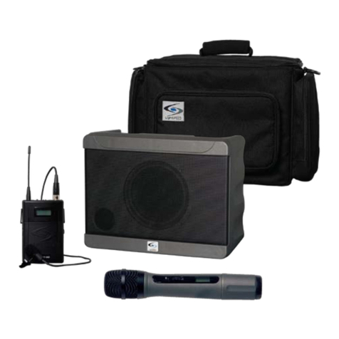
Lightspeed DELTA PA User manual

User Manual
DELTA PA
ON


TABLE OF CONTENTS
SECTION 1: 4 Safety Instructions
5 System Components and Unpacking
Overview 6 Optional Components
7 Top Panel Wireless Receiver Controls
8 Top Panel Controls & Connections
9 Rear Panel Controls & Connections
10 Installing or Replacing Receiver Module
SECTION 2: 11 Step 1. Connecting the DELTA PA Receiver
to a Power Supply
Set-up & Use 12 Step 2A. Setting up one DELTA PA Receiver
13 Step 2B. Using More Than One DELTA PA
Receiver
Handheld Transmitter
14 Step 3. Channel Selection
15 Step 4. Battery Life & Battery Type
16 Step 5. Replacing Battery
17 Step 6. Recharging Batteries
Belt-pack
18 Step 7. Connecting & Placement
19 Step 8. Channel Selection
20 Step 9. Gain Adjust
21 Step 10. Battery Life Indicator & Type
22 Step 11. Replacing Batteries
23 Step 12. Recharging Batteries
24 Daily Use Instructions
SECTION 3: 25 Hand Held Microphone Transmitter
Optional Accessories 26
27
Belt-Pack Transmitter
Optional Speaker Stand and Bracket
Assembly
SECTION 4: 28 Troubleshooting Guide
Troubleshooting
SECTION 5: 29 Warranty Statement
Warranty &
Specications
30 Safety Warnings
31 System Specications

4
1. Overview 2. Setup & Use 3. Optional
Accessories 4. Troubleshooting 5. Warranty, Safety
& Specications
IMPORTANT SAFETY INSTRUCTIONS
1. Read these instructions.
2. Keep these instructions.
3. Heed all warnings.
4. Follow all instructions.
5. Do not use the apparatus near
water.
6. Clean only with dry cloth.
7. Do not block any ventilation
openings. Install in
accordance with the
manufacturer’s instructions.
8. Do not install near any heat
sources such as radiators,
heat registers, stoves, or
other apparatus (including
amplifiers) that produce heat.
9. Do not defeat the safety
purpose of the polarized
or grounding-type plug.
A polarized plug has two
blades with one wider than
the other. A grounding- type
plug has two blades and a
third grounding prong. The
wide blade or the third prong
is provided for your safety. If
the provided plug does not
fit into your outlet, consult an
electrician for replacement of
the obsolete outlet.
10. Protect the power cord
from being walked on or
pinched particularly at plugs,
convenience receptacles, and
the point where they exit from
the apparatus.
11. Only use attachments/
accessories specified by the
manufacturer.
12. Use only with a cart, stand,
tripod, bracket or table
specified by the manufacturer,
or sold with the apparatus.
When a cart is used, use
caution when moving the
cart/apparatus combination to
avoid injury from tip-over.
13. Unplug this apparatus during
lightning storms or when
unused for long periods of
time.
14. Refer all servicing to qualified
service personnel. Servicing is
required when the apparatus
has been damaged in any
way, such as power-supply
cord or plug is damaged,
liquid has been spilled or
objects have fallen into the
apparatus, the apparatus
has been exposed to rain or
moisture, does not operate
normally, or has been
dropped.
15. When the mains plug or
appliance coupler is used as
the disconnect device, it shall
remain readily operable.
16. Please keep the unit in a good
ventilation environment.
17. WARNING: To reduce the risk
of re or electric shock, do not
expose this apparatus to rain or
moisture.
18. Apparatus shall not be
exposed to dripping or
splashing and no objects lled
with liquids, such as vases, shall
be placed on the apparatus.
5
1. Overview 2. Setup & Use 3. Optional
Accessories 4. Troubleshooting 5. Warranty, Safety
& Specications
SECTION 1:
OVERVIEW
SYSTEM COMPONENTS AND UNPACKING
The standard conguration of the DELTA PA will contain:
DELTA PA Carry Case
DELTA PA Public
Address System
and Power Supply

6
1. Overview 2. Setup & Use 3. Optional
Accessories 4. Troubleshooting 5. Warranty, Safety
& Specications
OPTIONAL COMPONENTS
Optional equipment which may be part of your DELTA PA system:
Individual Components
DPA016R 16 Channel UHF Receiver Module
HM016 16 Channel UHF Handheld Transmitter
MH7 Mic Holder for HM016 Handheld Transmitter
BP016 16 Channel UHF Belt-Pack Transmitter
BC016 Battery Charger for BP016 or HM016
831S Audio-Technica 831 Lapel Mic
TK250S Lightspeed Noise-cancelling Headset Mic
24V-2.5-A AC Power Supply
NH1 AA NiMH Rechargeable Battery
SPDPA Carry Bag for DELTA PA
AC-PWR-NA AC North American Power Cable
Optional Accessories
GTC900 Guitar/aux In Cable for BP016
TWBRK Speaker Stand Bracket
SS1 Tripod Speaker Stand
SPSS1 Carry Bag for Tripod Speaker Stand
H10 Wired Dynamic Handheld Mic
BP016 Transmitter and
Charger
TK250S Noise-
Cancelling Headset
Microphone
831S Audio
-Technica 831
Lapel Mic
HM016 Transmitter
ON

7
1. Overview 2. Setup & Use 3. Optional
Accessories 4. Troubleshooting 5. Warranty, Safety
& Specications
TOP PANEL: WIRELESS RECEIVER CONTROLS
5. TRANSMITTER LOW BATTERY
INDICATOR: This LED will light
to indicate the batteries in the
corresponding transmitter are
low.
6. SCAN: Press this button to auto-
matically select a channel that is
free from interference.
7. SQUELCH LEVEL ADJUSTMENT:
Covered with a plastic cap, the
squelch is adjusted at the factory
to provide the best signal level
and minimum noise. There is no
need to adjust the squelch level
in the eld.
1. WIRELESS RECEIVER 1: One or
two wireless receiver modules are
located at the top panel.
2. CHANNEL DISPLAY: An LED
readout of the receiver module
indicates which channel you are
on.
3. CHANNEL CONTROL (1-16): The
left button increments the channel
number (1-16). Each touch of the
button moves the number up one
until it gets to sixteen. The right
button decrements the channel
number (16-1).
4. RF CHANNEL A/B INDICATOR:
The “A” LED lights up indicating
the A channel tuner is receiving
the strongest RF signal. The “B”
LED lights up indicating the “B”
channel tuner is receiving the
strongest RF signal.
POWER
CHARGE
RED: LOW BATT GREEN: ON
RED: CHARGING GREEN: FULL
RECVR 1
RECVR 2
RECVR 2
O/I
POWER/
RECVR 1
1
2
36
5
7
4

8
1. Overview 2. Setup & Use 3. Optional
Accessories 4. Troubleshooting 5. Warranty, Safety
& Specications
TOP PANEL CONTROLS AND
CONNECTIONS
1. BASS: Controls the level of low
frequency sound output for the
system.
2. TREBLE: Controls the level of
high frequency sound output for
the system.
Note: Reducing Feedback
The BASS and TREBLE controls
can be used to reduce feedback
(“squealing” or “howling”). If you
hear high-pitched squealing, lower
the treble setting. If you hear low-
pitched howling, lower the bass
setting.
3. AUX IN/MIC IN: Controls the
volume of a wired microphone
plugged into MIC IN on the back
of the system and the volume of
an auxiliary piece of equipment
plugged into the AUX IN on the
back of the system.
4. WIRELESS RECVR 2: Controls the
volume of Wireless Microphone
2 if a second wireless receiver is
installed.
5. POWER/WIRELESS RECVR 1:
Turn this knob clockwise to power
up the system. Rotate to adjust the
volume of Wireless Microphone 1.
6. POWER LED:Green = Power On.
Red = Low Battery
7. CHARGING LED:Green = Full
Charge. Red = Charging
*Note: Internal Delta PA lithium
ion battery must be replaced
by licsensed Lightspeed service
center. Broken warning label will
void warranty.
1
2
3
7
5
4
POWER
CHARGE
RED: LOW BATT GREEN: ON
RED: CHARGING GREEN: FULL
RECVR 1
RECVR 2
RECVR 2
O/I
POWER/
RECVR 1
6

9
1. Overview 2. Setup & Use 3. Optional
Accessories 4. Troubleshooting 5. Warranty, Safety
& Specications
1
2
3
5
4
REAR PANEL CONTROLS AND CONNECTIONS
a line level output signal that
can be connected to a recorder,
assistive listening device, etc.
6. SPEAKER OUT (SWITCHED): This
¼” jack can be used to connect
to an external passive speaker.
[NOTE: connection to this jack will
mute the internal speaker of the
DELTA PA.]
*Note: Wiring to these terminals
should follow the Class 2 wiring
methods as outlined in the
National Electric Code.
7. FUSE: The fuse holder is
accessible using a at-blade
screwdriver. Push in and rotate ¼
turn counterclockwise to remove.
[NOTE: replacement is a 3.15A SB
250V slow blow fuse.]
8. DC POWER: This jack provides
a connection for the DELTA PA
power supply.
1. MIC IN: This ¼” jack provides
an input for a wired handheld
microphone.
2. AUX IN: This 3.5 mm jack
provides an input for audio from
an external device, such as a
CD player, MP3 player, TV/VCR,
computer, etc.
3. AUX OUT: This 3.5 mm jack
provides an adjustable-level
audio output that can be
connected to a recorder or
assistive listening device.
4. AUX OUT VOLUME: This knob
controls the level of the 3.5 mm
AUX OUT jack. Counterclockwise
represents a microphone level
signal, while fully clockwise
represents a line level signal.
5. AUX OUT: This ¼” jack provides
6
7
8

10
1. Overview 2. Setup & Use 3. Optional
Accessories 4. Troubleshooting 5. Warranty, Safety
& Specications
INSTALLING OR REPLACING A RECEIVER
MODULE
NOTE: Make sure the DELTA PA is
turned off.
1. Remove the two screws securing
the module panel using a small
phillips head screwdriver.
2. Remove the module from the
enclosure by carefully inserting
the blade of a small, at-blade
screwdriver under the face plate
edge and nudging it upward.
3. Grasp the edges of the module
with both hands and slide
it out.
4. Install the new module by
aligning it with the guide rails and
sliding all the way in to engage
the connector at the rear of the
module.
5. Replace the two screws.
POWER
CHARGE
RED: LOW BATT GREEN: ON
RED: CHARGING GREEN: FULL
RECVR 1
RECVR 2
RECVR 2
O/I
POWER/
RECVR 1

11
1. Overview 2. Setup & Use 3. Optional
Accessories 4. Troubleshooting 5. Warranty, Safety
& Specications
SECTION 2:
SET-UP & USE
1. CONNECTING THE DELTA PA RECEIVER
TO A POWER SUPPLY
1. Locate the power supply.
2. Insert the DC connector into the
“POWER INPUT” connector on the
bottom of the DELTA PA and plug
the other end to an electrical
outlet.
3. Turn the POWER/RCVR1 knob
clockwise to turn the system
on.
4. The green LED light next to the
knob will illuminate to conrm the
system is powered up.
*Note: The DELTA PA can operate
on either DC power or battery
power.
POWER
CHARGE
RED: LOW BATT GREEN: ON
RED: CHARGING GREEN: FULL
RECVR 1
RECVR 2
RECVR 2
O/I
POWER/
RECVR 1
POWER
CHARGE
RED: LOW BATT GREEN: ON
RED: CHARGING GREEN: FULL
RECVR 1
RECVR 2
RECVR 2
O/I
POWER/
RECVR 1
Note: When the DELTA PA is received,
plug in the power supply and let charge
overnight before using.

12
1. Overview 2. Setup & Use 4. Troubleshooting 5. Warranty, Safety
& Specications
2A. SETTING UP ONE DELTA PA RECEIVER
1. Turn the DELTA PA ON by rotating
the POWER/RCVR 1 knob
clockwise. The green LED will
light.
Channel Selection: Receiver
Each Receiver has 16 user-selectable
channels to choose from. You can
either select a channel manually or
by pressing the SCAN button, which
will automatically select a clear
channel.
2. Clear Channel SCAN
(recommended):
A) Make sure the transmitter(s) is
OFF before pressing this button.
When this button is pressed, the
receiver will cycle through all
16 channels and select a clear
frequency. (This process takes
about 20 seconds.)
B) Once the receiver selects the
clear channel, you will need to
select the same channel on the
corresponding transmitter
(handheld or belt-pack). See
pages 14 and 19 for instructions.
NOTE There are 3 different
groupings of 16 channels available
(620, 640, 660 MHz). Make sure the
receiver module frequency group
is the same frequency group as the
transmitter.
ON
Channel 2
POWER
CHARGE
RED:LOW BATT GREEN: ON
RED:CHARGING GREEN: FULL
RECVR 1
RECVR 2
RECVR 2
O/I
POWER/
RECVR 1
POWER
CHARGE
RED: LOW BATT GREEN: ON
RED: CHARGING GREEN: FULL
RECVR 1
RECVR 2
RECVR 2
O/I
POWER/
RECVR 1

13
1. Overview 2. Setup & Use 3. Optional
Accessories 4. Troubleshooting 5. Warranty, Safety
& Specications
2B. USING MORE THAN ONE DELTA PA
RECEIVER
If you have a second DELTA PA:
A) Verify that RECVR 1
transmitter and receiver 1 are on
and set to the same clear channel.
B) Make sure the transmitter for
RECVR 2 is turned off.
C) Press the SCAN button on the
RECVR 2.
D) After the RECVR 2 receiver
selects a clear channel, set
the RECVR 2 transmitter
(handheld or belt-pack) to the
selected channel. See pages 14
and 19 for instructions.
3. Manual Channel Selection:
A) Pressing the UP CHANNEL
button increases the channel
number by one.
B) Pressing the DOWN CHANNEL
button decreases the channel
number by one.
C) Once a frequency is selected,
you will need to select the same
channel on the corresponding
transmitter (handheld or belt-
pack). See pages 14 and 19 for
instructions.
4. Set the Receiver 1 and Receiver 2
channels on the second DELTA PA
to be the same as the rst DELTA
PA.
ON
Channel 2

14
1. Overview 2. Setup & Use 4. Troubleshooting 5. Warranty, Safety
& Specications
3. CHANNEL SELECTION: HANDHELD
TRANSMITTER
Once a channel has been selected
on the receiver, you now need to
select that same channel on the
handheld transmitter. If you have a
belt-pack transmitter, go to page 19
for channel selection instructions.
1. Turn on the microphone by sliding
the power button on the barrel
forward. The LED will ash red.
2. Use a screwdriver to set the
channel switch to the current
channel shown on the RECVR
screen.
Transmitters and receivers are
available in 3 different frequency
groups (620, 640, 660 MHz). Verify
that the receiver frequency matches
the letter code on the silver sticker
in the battery compartment of the
transmitter.
Model Number: HM016
Serial Number
HM01614324024
FREQUENCY 660 MADE IN TAIWAN
ON
Same
Channel
ON
Frequency

15
1. Overview 2. Setup & Use 3. Optional
Accessories 4. Troubleshooting 5. Warranty, Safety
& Specications
ON
4. BATTERY LOW INDICATOR AND BAT-
TERYTYPE ON HANDHELD MICROPHONE
Battery Low Indicator
Battery low indicator is located
above the power switch. It glows red
when the battery charge is low and
recharging is necessary
Battery Type
The transmitter will operate with
either standard AA alkaline batteries
or nickel metal hydride (NiMH)
rechargeable batteries. Since these
types of batteries have different
characteristics, it is important not to
mix battery types. Use only AA NiMH
batteries when recharging.
NOTE: Do not mix battery types.
WARNING: Do not use NiCad
batteries! They will not charge
properly and may cause damage to
the transmitter.
Lightspeed recommends Panasonic
or Energizer batteries. Duracell may
not work.
Low Battery Light

16
1. Overview 2. Setup & Use 4. Troubleshooting 5. Warranty, Safety
& Specications
ON
5. REPLACING BATTERIES IN HANDHELD
MICROPHONE
Replacing the Batteries
1. Unscrew the end cap to reveal the
battery compartment.
2. Remove or replace the batteries
as shown. The microphone
requires two AA sized batteries
stacked end to end.
3. Note the polarity in the battery
compartment.
IMPORTANT: Replace batteries
with the same type, (alkaline or
NiMH), that were installed in your
Handheld Microphone. Lightspeed
recommends Panasonic or Energizer
batteries. Duracell may not work
properly.

17
1. Overview 2. Setup & Use 3. Optional
Accessories 4. Troubleshooting 5. Warranty, Safety
& Specications
6. RECHARGING BATTERIES IN HANDHELD
MICROPHONE
Recharging the Batteries
(NiMH Rechargeable Batteries
ONLY):
Make sure there are NiMH
rechargeable batteries in the
transmitter before plugging in
the charger. A full charge will be
attained in 8-10 hours. Fully charged
Lightspeed microphones will last
over 7 hours.
WARNING: Do not attempt to
charge alkaline batteries. They can
overheat and expand, creating a
signicant hazard and damaging the
transmitter. (This is not covered by
warranty.)
1. Switch the transmitter power OFF.
2. Insert the small DC plug into the
jack on the bottom of
the transmitter.
3. Plug the other end of the charger
into any standard 110 VAC outlet.
4. The red LED on the charger will
light, indicating that charging is in
progress.
5. When the batteries are fully
charged, the LED on the charger
will glow green.
ON

18
1. Overview 2. Setup & Use 4. Troubleshooting 5. Warranty, Safety
& Specications
7. CONNECTING AND PLACING BELT-PACK
TRANSMITTER
Connecting the Microphone
To connect the microphone, simply
insert the microphone connector
into the TA4F connector on top of
the transmitter. To remove, press
the black button on the microphone
connector and pull out.
Microphone Options
Lightspeed offers two types of
microphones that can be used with
this system. The BP016 Transmitter
can be used with either a lapel
style microphone or a headset
microphone. Both plug into the top
of the transmitter as shown.
Lapel Microphone Placement
Simply connect the microphone cord
directly into the jack on top of the
transmitter and clip the microphone
to lapel or collar. For optimal sound,
position the microphone as close to
the mouth as possible.
Headset Microphone Placement
Simply connect the microphone
cord directly into the jack on top
of the transmitter and place the
headset around the back of the
head. For optimal sound, position
the microphone at the corner of the
mouth.

19
1. Overview 2. Setup & Use 3. Optional
Accessories 4. Troubleshooting 5. Warranty, Safety
& Specications
8. CHANNEL SELECTION: BELT-PACK
TRANSMITTER
Channel Selection:
Once a channel has been selected
on the receiver, you now need to
select that same channel on the belt-
pack transmitter.
1. Turn the transmitter power on by
sliding the PWR button to on. The
LED will ash red.
2. Open the battery compartment
door by depressing the latches on
each side of the transmitter.
3. Use the screwdriver channel set
to switch to the current channel
shown on the receiver.
Transmitters and receivers are
available in 3 different frequency
groups (620, 640, 660 MHz). Verify
that the frequency group of the
receiver matches the letter code
on the silver sticker in the battery
compartment of the transmitter.
Model Number: BP016
Serial Number
BP01614324024
FREQUENCY 660 MADE IN TAIWAN

20
1. Overview 2. Setup & Use 4. Troubleshooting 5. Warranty, Safety
& Specications
9. GAIN ADJUST ON BELT-PACK
TRANSMITTER
NOTE: If you are using a high impedance
source, such as a guitar, it will be necessary to
adjust the GT dial. Using a high impedance
source requires a special cable. Contact
Lightspeed Customer Service at 800-732-
8999 for more information. Customers in
Canada should contact their local reseller.
Gain Adjust:
When changing microphones or
users, it may be necessary to adjust
the transmitter gain based on
differing microphones sensitivities
and voice levels.
To adjust the gain:
1. Open the battery compartment
door by depressing the latches on
each side of the transmitter.
2. Turn the MT dial clockwise
to increase the gain and
counterclockwise to decrease the
gain.
Other manuals for DELTA PA
1
Table of contents
Other Lightspeed Microphone System manuals

Lightspeed
Lightspeed Delta X6 User manual

Lightspeed
Lightspeed MULTIMIKE User manual

Lightspeed
Lightspeed TOPCAT User manual

Lightspeed
Lightspeed Flexmike User manual

Lightspeed
Lightspeed FP 1000 User manual

Lightspeed
Lightspeed Delta X6 User manual

Lightspeed
Lightspeed Access Link User manual

Lightspeed
Lightspeed Access Link User manual