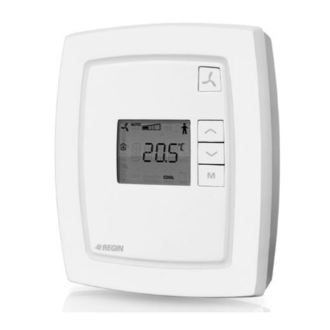
Regin Corrigo E series User manual

Corrigo E - User Manual
Heating

DISCLAIMER
The information in this manual has been carefully checked and is believed to be correct. Regin however, makes no
warranties as regards the contents of this manual and users are requested to report errors, discrepancies or ambiguities to
Regin, so that corrections may be made in future editions. The information in this document is subject to change
without prior notification.
The software described in this document is supplied under licence by Regin and may be used or copied only in
accordance with the terms of the licence. No part of this document may be reproduced or transmitted in any form, in
any fashion, electronically or mechanically, without the express, written permission of Regin.
COPYRIGHT
© AB Regin. All rights reserved.
TRADEMARKS
Corrigo E, E-tool, EXOdesigner, EXOreal, EXO4, EXOline, EXO4 Web Server, Optigo, Regio and Regio Tool©are
registered trademarks of AB Regin.
Windows, Windows 2000, Windows XP, and Windows Server 2003 are registered trademarks of Microsoft
Corporation.
Some product names mentioned in this document are used for identification purposes only and may be the registered
trademarks of their respective companies.
Revision G, Dec 2007
Document Revision: 1.7-1-01

Table of contents
Chapter 1 About the manual 4
Chapter 2 About Corrigo E 5
Chapter 3 Installation and wiring 8
Chapter 4 Commissioning 15
Chapter 5 Functional description 17
Chapter 6 Display, LEDs and buttons 22
Chapter 7 Access rights 24
Chapter 8 Configuration 26
Chapter 9 Settings 38
Chapter 10 Time settings 41
Chapter 11 Actual / Setpoint 43
Chapter 12 Manual / Auto 45
Chapter 13 Energy / Cold water 47
Chapter 14 Other functions 49
Chapter 15 Index 50

Corrigo E Heating manual, revision G Chapter 1 About the manual 4
Chapter 1 About the manual
This manual covers all the models in the Corrigo E series of heating controllers. This revision
covers program revision 1.7-1-01.
More information
More information about Corrigo E can be found in:
•Manual E-tool – Manual of how to configure the controllers
•Lon-interface variable list – Variable list for the Corrigo E series
•Network variables for EXOline and Modbus – Variable list for EXOline and Modbus
communication
•CE - Declaration of conformity, Corrigo E
The information is available for download from Regin’s homepage, www.regin.se.

Corrigo E Heating manual, revision G Chapter 2 About Corrigo E 5
Chapter 2 About Corrigo E
Corrigo E for heating is a complete new range of programmable controllers for control of building
heating systems.
Corrigo E series for heating comprises three model sizes: 8, 15 or 28 in-/outputs.
Available with or without front panel display and buttons. For units without front panel display and
buttons a separate, cable-connected terminal E-DSP with display and buttons is available.
All programming and normal handling can be done using the display and buttons or from a
connected computer running Corrigo E-tool.
The temperature controllers are PI-controllers for heating control and tap hot-water control with a
pre-programmed set of control modes. To the controllers can be bound a number of different control
functions and analogue and digital input and output functions. The choice of which functions are to
be used is free, the only restriction lying in the physical number of inputs and outputs that the
different models have.
The Corrigo is designed for DIN-rail mounting.
The program for a heating unit contains, apart from other things, the following functions:
Heating sequence control:
Control of 1 - 3 individual heating circuits.
Tap hot water control:
1 or 2 tap hot water circuits and 1 storage-tank charger circuit.
Differential pressure control
One constant differential pressure control circuit
Boiler control
Basic two step boiler control.
Timer outputs
Up to 5 individually settable timer outputs for control of, for example, lighting, door locks etc.
Timer control
Year-base clock, individual schedulers, holiday scheduler.
Water consumption
Energy consumption

Corrigo E Heating manual, revision G Chapter 2 About Corrigo E 6
Corrigo E hardware overview
Model 8 8D 15 15D 28 28D
Analogue Inputs 2 2 4 4 4 4
Digital Inputs 3 3 4 4 8 8
Universal Inputs - - - - 4 4
Analogue Outputs 1 1 3 3 5 5
Digital Outputs 2 2 4 4 7 7
RS485 Yes Yes Yes Yes Yes Yes
LON Option Option Option Option Option Option
TCP/IP Option Option Option Option Option Option
Display No Yes No Yes No Yes
Ext. display Option No Option No Option No
Technical data
Protection class ..................................................................................................................IP20
Display........................................................4 rows of 20 characters. Background illumination.
LEDs
Yellow.......................................................................................................Settable parameter
Red.................................................................................................................................Alarm
Clock ..................................................................Year base 24 hour clock with battery backup.
Automatic summer-/winter-time changeover.
Operating system..........................................................................................................EXOreal
Supply voltage...................................................................................................24 V AC, 6 VA
Dimensions....................................................................148x123x60 (WxHxD incl. terminals)
Casing......................................................................................................... Standard Euronorm
Mounting................................................................................................................On DIN-rail
Operation
Climatic conditions according to IEC 721-3-3........................................................Class 3k5
Ambient temperature................................................................................................. 0...50°C
Ambient humidity..............................................................................................Max 95% RH
Mechanical requirements according to IEC721-3-3 ..............................................Class 3M3
Vibration..........................................................IEC60068-2-6, Test FC, vibration Sinusoidal
Shock................................................................................................IEC60068-2-27, Test Ea
Transport
Climatic conditions according to IEC 721-3-2........................................................Class 2k3
Ambient temperature..............................................................................................-20...70°C
Air humidity ......................................................................................................Max 95% RH
Mechanical requirements according to IEC721-3-2 ..............................................Class 2M2
Vibration..........................................................IEC60068-2-6, Test FC, vibration Sinusoidal
Shock................................................................................................IEC60068-2-27, Test Ea
Free fall............................................................................................ IEC60068-2-27, Test Ed
Storage
Climatic conditions according to IEC 721-3-1........................................................Class 1k3
Ambient temperature..............................................................................................-20...70°C
Air humidity ......................................................................................................Max 95% RH
Battery
Type....................................................................................................Replaceable Lithium cell
Battery life....................................................................................................Better than 5 years
Warning.................................................................................................... Low battery warning
Battery backup...............................................................................Memory and real time clock
Communication
EXOline Port 1, insulated via a built-in RS485 contact.
The basic version of Corrigo E can communicate with Modbus. You do not need an activation code.
Corrigo E can be ordered with a communication port for TCP/IP or LON.

Corrigo E Heating manual, revision G Chapter 2 About Corrigo E 7
CE-marking
Conforms with the EMC standards: CENELEC EN61000-6-3:2001, CENELEC EN61000-6-
1:2001.
Inputs
Analogue inputs AI..............................................Settable 0…10 V DC or PT1000, 12 bit A/D
Digital inputs DI.......................................................................................Potential free closure
Universal inputs UI...........................................Can be set to act as either an analogue input or
a digital input with specifications as above
Outputs
Analogue outputs AO.......................................................Settable 0…10 V DC; 2…10 V DC;
10…0 V DC or 10…2 V DC
8 bit D/A short-circuit protected
Digital outputs DO ..................................................Triac outputs, 24 V AC, 0.5 A continuous
Options
LON...................................................................FT3150, gives a second communication route
TCP/IP..................................................Replaces RS485 for EXOline (Port 1) communication
External hand terminal, E-DSP ...........................For use with Corrigo E units without display
Position of the terminals on Corrigo E

Corrigo E Heating manual, revision G Chapter 3 Installation and wiring 8
Chapter 3 Installation and wiring
3.1 Installation
Corrigo E can be mounted in a DIN-standard casing (minimum 9 modules), on a DIN-rail in a
cabinet or, using a suitable front-mounting kit, in a cabinet door or other control panel.
Ambient temperature: 0…50°C.
Ambient humidity. Max. 95 %RH, non-condensing.
3.2 Wiring
At the end of this chapter there are wiring diagrams showing the factory set configuration. We have
also included blank diagrams. Since the function of most of the inputs and outputs depends on the
programming of the unit the final wiring diagram cannot be filled in until the installer has decided
how to use the inputs/outputs. It is important to make sure that the wiring is correctly done and in
accordance with the instructions given in this manual.
3.2.1 Supply voltage
24 V AC ±15%, 50/60 Hz. 6 VA
If the Corrigo E and the actuators connected to it share the same transformer it is essential that the
same transformer-pole is used as reference for all the equipment. Failure to do so will prevent the
equipment from functioning as intended and may also lead to damages.
3.2.2 Inputs and outputs
The list of input and output functions in section 3.2.3 is a handy instrument to help you keep track
of which inputs and outputs you will need to configure.
Analogue inputs
Analogue inputs must refer to an A-gnd terminal placed in the same terminal block as the input
being wired.
Analogue inputs can, depending on the configuration, be used for either PT1000 temperature
sensors or for 0…10 V DC analogue input signals, for example from a pressure transmitter.
Digital inputs
Digital inputs must refer to C+ on terminal 4. Digital inputs may only be wired to voltage-free
contacts. Any external voltage applied to a digital input may harm the unit.
Universal inputs
A universal input can be configured to act as either an analogue input or as a digital input.
A universal input configured as analogue input must refer to an A-gnd terminal placed in the same
terminal block as the input being wired.
A universal inputs configured as an analogue input can, depending on the configuration, be used for
either PT1000 temperature sensors or for 0…10 V DC analogue input signals, for example from a
pressure transmitter.
A universal input configured as a digital input must refer to C+ on terminal 4. It may only be wired
to voltage-free contacts.

Corrigo E Heating manual, revision G Chapter 3 Installation and wiring 9
Analogue outputs
Analogue outputs must refer to the A-gnd terminal placed in the AO terminal block.
All analogue outputs can be individually set to any one of the following signals:
0…10 V DC
2…10 V DC
10…0 V DC
10…2 V DC
If the Corrigo E and the actuators connected to it share the same transformer it is essential that the
same transformer-pole is used as reference for all the equipment. Failure to do so will prevent the
equipment from functioning as intended and may also lead to damages.
Digital outputs
Digital outputs must refer to G on terminal 10.
All the digital outputs are triac controlled. The outputs will deliver 24 V AC, 0.5 A continuous. The
outputs cannot be used to drive DC relays.
10
11
12
3.2.3 Input and output lists
Use these lists during commissioning to help you keep track of which input and output functions
you wish to use.
Analogue inputs
9Analogue input signal
Outdoor temperature sensor
Supply temperature Heating sequence1
Tap hot water circuit 1, supply temperature
Return temperature Heating sequence1
Tap hot water circuit 2, supply temperature
Storage tank supply temperature
Storage tank return temperature
Wind-speed transmitter, 0…10 V DC
Differential pressure transmitter, 0…10 V DC
Supply temperature Heating sequence2
Return temperature Heating sequence2
Room temperature Heating sequence2
Room temperature Heating sequence1
Supply temperature Heating sequence3
Return temperature Heating sequence3
Room temperature Heating sequence3
Boiler temperature

Corrigo E Heating manual, revision G Chapter 3 Installation and wiring 10
Digital inputs
9Digital input signal
Run-indication/alarm circulation pump, P1A-HS1
Run-indication/alarm circulation pump, P1B-HS1
Run-indication/alarm circulation pump, P1A-HS2
Run-indication/alarm circulation pump, P1B-HS2
Run-indication/alarm circulation pump, P1-HW1
Volume pulses, heating usage
Volume pulses, cold water usage 1
Energy pulses, heating usage
Pressure switch, expansion vessel pressure
External alarm
Boiler alarm
Run-indication/alarm circulation pump, P1A-HS3
Run-indication/alarm circulation pump, P1B-HS3
Run-indication/alarm frequency converter for
pressure control
Run-indication/alarm storage tank charge pump
P1-HP
External power limitation
Volume pulses, cold water usage 2
Energy pulses, electricity meter
Note: The universal inputs on Corrigo E28 can, individually, be configured as either analogue
inputs using any of the analogue input signals above or as digital inputs using any of the digital
input signals above.
Analogue outputs
9Analogue output signal
Valve actuator, Heating sequence1, HS1
Valve actuator, hot water circuit 1, HW1
Valve actuator, Heating sequence2, HS2
Valve actuator, Heating sequence3, HS3
Valve actuator, hot water circuit 2, HW2
Frequency converter, pressure control
Split of any one of the above circuits

Corrigo E Heating manual, revision G Chapter 3 Installation and wiring 11
Digital outputs
9Digital output signal
Start/stop pump, P1A-HS1
Start/stop pump, P1B-HS1
Actuator HS1 increase
Actuator HS1 decrease
Start/stop pump, P1-HW1
Start/stop pump, P1A-HS2
Start/stop pump, P1B-HS2
Actuator HS2 increase
Actuator HS2 decrease
Start/stop pump, P1A-HS3
Start/stop pump, P1B-HS3
Actuator HS3 increase
Actuator HS3 decrease
Actuator HW1 increase
Actuator HW1 decrease
Actuator HW2 increase
Actuator HW2 decrease
Start/stop charge pump for storage tank, P1-HP1
Start frequency converter for diff pressure control
Start step 1, boiler
Start step 2, boiler
Time channel 1
Time channel 2
Time channel 3
Time channel 4
Time channel 5
Sum alarm A
Sum alarm B
Sum alarm A + B

Corrigo E Heating manual, revision G Chapter 1 12
Wiring diagram Corrigo E28 factory configuration
(See also picture of the position of the terminals on page 7)
1 G 50 B
2 G0 Supply voltage 24 V AC, ±15%. 50/60 Hz 51 A
3 Protective earth 52 N
4 +C +24 V DC. Reference for digital inputs DI. 53 E
RS485 EXOline / Modbus
10 G Reference for digital outputs DO. 57 Net+
11 DO1 Start/stop pump, P1A-HS1 58 Net-
12 DO2 Start/stop pump, P1B-HS1 59 Egnd
LON-connection (LON-versions only)
13 DO3 Actuator HS1 increase
14 DO4 Actuator HS1 decrease 71 DI1 Run-indication/alarm pump, P1A-HS1
15 DO5 Start/stop pump, P1-HW1 72 DI2 Run-indication/alarm pump, P1B-HS1
16 DO6 Start/stop pump, P1A-HS2 73 DI3 Run-indication/alarm pump, P1A-HS2
17 DO7 Sum alarm A + B 74 DI4 Run-indication/alarm pump, P1-HW1
75 DI5 Volume pulse, heating usage meter
30 Agnd Reference pole for analogue inputs AI 76 DI6 Energy pulse, heating usage meter
31 AI1 Outdoor temperature sensor 77 DI7 Volume pulse, cold water usage 1
32 AI2 Supply temp, heating sequence 1, HS1 78 DI8 Pressure switch, expansion vessel
33 Agnd Reference pole for analogue inputs AI
34 AI3 Supply temp, hot water sequence 1, HW1 90 Agnd Reference for analogue outputs AO
35 AI4 Return temp, heating sequence 1, HS1 91 AO1 Actuator Heating sequence1, HS1
92 AO2 Actuator Heating sequence2, HS2
40 Agnd Reference pole for universal inputs UI 93 AO3 Actuator Heating sequence3, HS3
41 UI1 Supply temp, heating sequence 2, HS2 94 AO4
42 UI2 Return temp, heating sequence 2, HS2 95 AO5
43 Agnd Reference pole for universal inputs UI
44 UI3 Room sensor heating sequence 1, HS1
45 UI4 Room sensor heating sequence 2, HS2
Wiring diagram Corrigo E15H factory configuration
1 G 50 B
2 G0 Supply voltage 24 V AC, ±15%. 50/60 Hz 51 A
3 Protective earth 52 N
4 +C +24 V DC. Reference for digital inputs DI. 53 E
RS485 EXOline / Modbus
10 G Reference for digital outputs DO. 57 Net+
11 DO1 Start/stop pump, P1A-HS1 58 Net-
12 DO2 Start/stop pump, P1B-HS1 59 Egnd
LON-connection (LON-versions only)
13 DO3 Start/stop pump, P1-HW1
14 DO4 Sum alarm A + B 71 DI1 Run-indication/alarm pump, P1A-HS1
72 DI2
Run-indication/alarm pump, P1B-HS1
30 Agnd Reference pole for analogue inputs AI 73 DI3 Run-indication/alarm pump, P1-HW1
31 AI1 Outdoor temperature sensor 74 DI4 Pressure switch, expansion vessel
32 AI2 Supply temp, heating sequence 1, HS1
33 Agnd Reference pole for analogue inputs AI 90 Agnd Reference for analogue outputs AO
34 AI3 Supply temp, hot water sequence 1, HW1 91 AO1 Actuator Heating sequence1, HS1
35 AI4 Return temp, heating sequence 1, HS1 92 AO2 Actuator Heating sequence2, HS2
93 AO3 Actuator Heating sequence3, HS3

Corrigo E Heating manual, revision G Chapter 1 13
Wiring diagram Corrigo E8H factory configuration
1 G 50 B
2 G0 Supply voltage 24 V AC, ±15%. 50/60 Hz 51 A
3 Protective earth 52 N
4 +C +24 V DC. Reference for digital inputs DI. 53 E
RS485 EXOline / Modbus
10 G Reference for digital outputs DO. 57 Net+
11 DO1 Start/stop pump, P1A-HS11 58 Net-
12 DO2 Start/stop pump, P1B-HS11 59 Egnd
LON-connection (LON-versions only)
30 Agnd Reference pole for analogue inputs AI 71 DI1 Run-indication/alarm pump, P1A-HS1
31 AI1 Outdoor temperature sensor 72 DI2 Run-indication/alarm pump, P1B-HS1
32 AI2 Supply temp, heating sequence 1, HS1 73 DI3 Pressure switch, expansion vessel
90 Agnd Reference for analogue output AO
91 AO1 Actuator Heating sequence1, HS1
Empty wiring diagram Corrigo E28H
1 G 50 B
2 G0 Supply voltage 24 V AC, ±15%. 50/60 Hz 51 A
3 Protective earth 52 N
4 +C +24 V DC. Reference for digital inputs DI. 53 E
RS485 EXOline / Modbus
10 G Reference for digital outputs DO. 57 Net+
11 DO1 58 Net-
12 DO2 59 Egnd
LON-connection (LON-versions only)
13 DO3
14 DO4 71 DI1
15 DO5 72 DI2
16 DO6 73 DI3
17 DO7 74 DI4
75 DI5
30 Agnd Reference pole for analogue inputs 76 DI6
31 AI1 77 DI7
32 AI2 78 DI8
33 Agnd Reference pole for analogue inputs
34 AI3 90 Agnd Reference for analogue outputs AO
35 AI4 91 AO1
92 AO2
40 Agnd Reference pole for analogue inputs 93 AO3
41 UI1 94 AO4
42 UI2 95 AO5
43 Agnd Reference pole for analogue inputs
44 UI3
45 UI4

Corrigo E Heating manual, revision G Chapter 1 14
Empty wiring diagram Corrigo E15H
1 G 50 B
2 G0 Supply voltage 24 V AC, ±15%. 50/60 Hz 51 A
3 Protective earth 52 N
4 +C +24 V DC. Reference for digital inputs DI. 53 E
RS485 EXOline / Modbus
10 G Reference for digital outputs DO. 57 Net+
11 DO1 58 Net-
12 DO2 59 Egnd
LON-connection (LON-versions only)
13 DO3
14 DO4 71 DI1
72 DI2
30 Agnd Reference pole for analogue inputs 73 DI3
31 AI1 74 DI4
32 AI2
33 Agnd Reference pole for analogue inputs 90 Agnd Reference for analogue outputs AO
34 AI3 91 AO1
35 AI4 92 AO2
93 AO3
Empty wiring diagram Corrigo E8H
1 G 50 B
2 G0 Supply voltage 24 V AC, ±15%. 50/60 Hz 51 A
3 Protective earth 52 N
4 +C +24 V DC. Reference for digital inputs DI. 53 E
RS485 EXOline / Modbus
10 G Reference for digital outputs DO. 57 Net+
11 DO1 58 Net-
12 DO2 59 Egnd
LON-connection (LON-versions only)
30 Agnd Reference pole for analogue inputs 71 DI1
31 AI1 72 DI2
32 AI2 73 DI3
90 Agnd Reference for analogue outputs AO
91 AO1

Corrigo E Heating manual, revision G Chapter 4 Commissioning 15
Chapter 4 Commissioning
General
Before the Corrigo can be used it must be configured, inputs and outputs must be assigned and all
relevant parameters must be set.
All commissioning can be done using the Corrigo front panel display and buttons or using the
display unit E-DSP.
Corrigo E-tool
The best way however, is to configure the Corrigo E by using Corrigo E-tool.
Corrigo E-tool is a PC-based configuration program specially developed to simplify the
commissioning of the Corrigo E-series.
When using E-tool the whole configuration and all settings can be done on the computer and then
downloaded to the Corrigo. An infinite number of different configurations can be saved in computer
memory for later use.
4.1 How to do it?
For configuration using E-tool, see the E-tool manual.
For configuration using the front panel there are two ways to go depending on how much help you
need.
Option 1:
•Jump straight to chapter 6 and 7, Display, buttons and LEDs and Access rights.
•After mastering the button and menu system, connect power to your Corrigo, log on at
System level and go to the menu Configuration.
•For the time being, skip the configuration menu Inputs/Outputs and start by configuring
Control functions.
•Run through the configuration menus in order and set whatever functions and parameters
you wish to include. Use chapter 4 of this manual for reference. Keep track of which inputs
and outputs you will need. To help you, there is a list of input and output functions
provided in chapter 3, (3.2.3 Input / Output list.)
•Finally, configure Inputs/Outputs.
•Exit Configuration and go to Settings
•Set the control values in Settings
•Set the clock and scheduler functions in Timers.
•Set the control setpoints in Actual/Setpoint.
Your Corrigo should now be ready to run.
Option 2:
Read this manual in the order given below: The manual has been designed to act as a guide through
the commissioning. The last chapters of the manual, not listed below, cover menus and functions
that are not used during commissioning.

Corrigo E Heating manual, revision G Chapter 4 Commissioning 16
Functional description
Start by reading the chapter 5.Functional description below. Some functions are essential to the
working of the unit and must be included. Others are more of the nature of optional extras which
can be excluded.
At the end of each function description there is a table of the necessary inputs and outputs to
implement the function. At the end of the manual there is a list of all the analogue and digital inputs
and outputs. As you read, mark in the list the inputs and outputs you will be using for the
application you are building. Note that the universal inputs in Corrigo E28 can, individually, be
configured as either analogue or digital inputs.
Display, buttons and LEDs
Read chapter 6 on how to use the front panel buttons to navigate the Corrigo E menu system.
Access rights
Chapter 7. Learn how to log in on the Corrigo E.
Configuration
Chapter 8. Configuration.
Connect power to the Corrigo. Using the buttons and menu system, go through the configuration
menus covering the functions you wish to use.
On delivery the units already have the inputs and outputs assigned to various functions. These can,
of course, be changed. In chapter 3 Installation and wiring there are two sets of wiring diagrams,
one set showing the pre-configured input / output configuration and one set where you can fill your
own configuration choices.
Settings
Set the control parameters, P-band, I-time for the temperature control loops in use.
Set the alarm parameters; alarm levels and delay times.
Timer settings
Set the clock and calendar functions
Setpoints
Set all the setpoints for all active control loops.
Hand/Auto
Learn to use manual control. Very useful for testing out your system.

Corrigo E Heating manual, revision G Chapter 5 Functional description 17
Chapter 5 Functional description
5.1 Heating systems
5.1.0 General
Corrigo E can be configured for 1 to 3 heating systems (radiator groups), HS1, HS2 and HS3.
5.1.1 Controllers
The heating system controllers are PI-controllers with settable P-band and I-time.
5.1.2 Control curves
The controllers have individual outdoor temperature / supply temperature control curves.
Each curve has 8 fix points. The default setting of the outdoor temperature values for the fix points
are -20, -15, -10, -5, ±0, +5, +10, +15. These can not be changed using the Corrigo front panel but
can be changed using E-tool. The corresponding supply temperature values are settable using the
front panel or E-tool.
5.1.3 Adaptation of curves
Room sensors can be used to correct the control curves. The average room temperature error over
24 hours is calculated. Values 1 hour before and 1 hour after a day/night or night/day change-over
are ignored. The curves are corrected once daily using the average room temperature error and a
settable correction factor. The correction will be a parallel displacement of the entire curve using the
following formula:
Displacement = (Room setpoint - Average temp)*Factor
5.1.4 Pump control
Each system can have single or double pumps. Double pumps are run one at a time with automatic,
weekly change over and automatic start of the backup pump on malfunction of the active pump.
Outdoor temperature dependent pump stop can be configured.
Pumps are exercised for 5 minutes at 3 pm daily.
5.1.5 Frost protection
If a controller is set to Off or Man(ual control) and the outdoor temperature is below a settable value
a minimum, settable supply temperature will be maintained and the pump will run.
5.1.6 Wind compensation
To compensate for wind chilling it is possible to connect a wind sensor and generate a setpoint
displacement according to a settable factor (°C per m/s).

Corrigo E Heating manual, revision G Chapter 5 Functional description 18
5.1.7 Building inertia and boost
The building inertia is settable to one of three levels: None, Medium, High.
The set inertia dictates the influence of outdoor temperature.
With no inertia, the outdoor temperature is used directly, with medium inertia a one-hour average is
used and with high inertia a 12-hour average is used.
Boost is used to speed up the raising of the indoor temperature when switching from night set back
temperature to normal comfort temperature. This is done by temporarily displacing the supply
temperature set-point curve. The following conditions must be met:
•Average outdoor temperature lower than 17°C
•Supply set-point value higher than 25°C
•Night set-back more than 2°C (room temperature)
The displacement is calculated as follows:
Displacem.=Factor*(17 - outdoor temp)*night set-back
Where Factor is settable 0…10 where 0 gives no boost and 10 gives high boost.
The time in minutes that boost will be active is calculated as follows:
Time = 1.6*(17 - Outdoor temp)
Time is limited to maximum 60 minutes.
5.1.8 Night set-back
Lowering of the night temperature is set in room temperature degrees. The corresponding lowering
of the supply temperature is calculated by the controller by multiplying the value by 3. The Corrigo
has individual schedules for each heating system with two comfort-temperature periods per day.
5.1.9 Power limitation
Using a digital input the power to the heating systems can be temporarily restricted. When activated,
the setpoints are lowered by a settable factor (% relative to 20°C). The limitation applies to all
configured heating systems.
The limitation is calculated as below:
Limited setpoint=20+(Setpoint-20)*Factor/100
Factor 100 gives no setpoint reduction, 0 gives full reduction to 20°C.
5.2 Tap hot water
5.2.0 General
Corrigo E can be configured for one or two tap hot-water systems HW1 and HW2. These have
constant supply-temperature control.
5.2.1 Controllers
The heating system controllers are PID-controllers with settable P-band, I-time and D-time.
5.2.3 Night set-back
The Corrigo E has individual schedules for each hot water system with two normal-temperature
periods per day.

Corrigo E Heating manual, revision G Chapter 5 Functional description 19
5.2.4 Pump control (HW1 only)
Corrigo E has a digital output signal that can be used to control the hot-water circulation pump in
HW1. The pump will run according to the settings of the night set-back schedule, running during
normal temperature periods and standing still during periods with reduced temperature.
5.2.5 Periodic overheating
Once daily, at 02:00 am the temperature set-point can be increased to 62°C to prevent growth of
Legionella bacteria. The raised set-point is maintained until the supply temperature reaches 60°C
but not shorter than 1 minute and not longer than 5 minutes. If the pump is stopped it will start and
run for the duration of the overheating period plus 2 minutes.
5.3 Storage tank
A storage tank function can be enabled.
The storage tank load pump, P1-HP1 is started depending on the storage tank supply water and
return water temperatures.
Loading is started if the return water temperature is lower than the set start temperature.
Loading is stopped when the supply temperature is higher than the set stop temperature and the
return temperature is higher than the set start temperature + the set differential.
5.4 Pressure control
Corrigo E can, using an analogue output signal, control a variable speed pump to maintain a
constant settable pressure. A digital output signal is available to give a start signal to the frequency
converter. This output is enabled as soon as the converter control signal rises above 0.1 V.
5.5 Boiler control
A simple boiler control can be enabled.
When the boiler temperature falls below Start temperature 1 the digital signal Start 1 will be
activated. Should the temperature fall below Start temperature 2 the digital output Start 2 will be
activated.
Any active outputs will be deactivated when the boiler temperature rises above the set Stop
temperature.
5.6 Cold-water monitoring
One or two circuits monitoring the cold-water usage can be configured each using a digital pulse-
input from a water meter. The pulse constant is settable. Maximum pulse rate is 2 Hz.
5.6.1 Values
The following values are calculated
•24 hour usage in litres, today
•24 hour usage in litres, yesterday
•24 hour usage in litres, day before yesterday
•Lowest hourly usage in litres, today
•Lowest hourly usage in litres, yesterday
•Usage total in m3. The value is resettable
•Water-flow (litres / min)

Corrigo E Heating manual, revision G Chapter 5 Functional description 20
5.6.2 Alarms
Pulse error If no pulses are detected within a settable time an alarm is activated. Setting
the time to 0 inhibits the alarm function.
High usage If the daily usage is higher than a settable value an alarm is activated.
Leakage control If the lowest hourly usage during the previous day is higher than a settable
value an alarm is activated.
5.7 Energy monitoring
One digital pulse function can be configured for heating energy monitoring. The pulse constant is
settable.
5.7.1 Usage values
The following usage values are calculated:
•24 hour usage in kWh, today
•24 hour usage in kWh, yesterday
•24 hour usage in kWh, day before yesterday
•Total usage in kWh or MWh. The value is resettable
5.7.2 Power values
Heating power is calculated by measuring the time between the energy pulses. The following power
values are calculated:
•Instantaneous value for a certain time or after a certain number of pulses
•Average of the above instantaneous value for the last hour
•Maximum value for the above instantaneous value
5.7.3 Leakage monitoring
Once a week, the control valves will be closed and the energy usage measured for a preset time. An
alarm is generated if the energy leakage is larger than a settable value, default 3000 W. The time for
and duration of the leakage monitoring is settable. Default is Sundays at 2:00 am for 30 minutes.
5.7.4 Alarms
Pulse error If no pulses are detected within a settable time an alarm is activated. Setting
the time to 0 inhibits the alarm function.
High usage If the daily usage is higher than a settable value an alarm is activated.
5.8 Electricity meter
One digital pulse function can be configured for electricity energy monitoring. The pulse constant is
settable.
5.8.1 Usage values
Total usage in MWh. The value is resettable.
Other manuals for Corrigo E series
1
This manual suits for next models
11
Table of contents
Other Regin Temperature Controllers manuals
Popular Temperature Controllers manuals by other brands

GE Security
GE Security ZP720-3 Installation sheet

Siemens
Siemens SITRANS Series Compact operating instructions

alre
alre BTF2 quick start guide

Ariston Thermo
Ariston Thermo MGM 2-ZONE HOT/COLD Installation and operating instructions

ECOWITT
ECOWITT WH0310 manual

Lux Elements
Lux Elements CONCEPT-BA-EH ZA Mounting and operating instructions