manuals.online logo
Brands
  1. Home
  2. •
  3. Brands
  4. •
  5. Lince
  6. •
  7. Security Sensor
  8. •
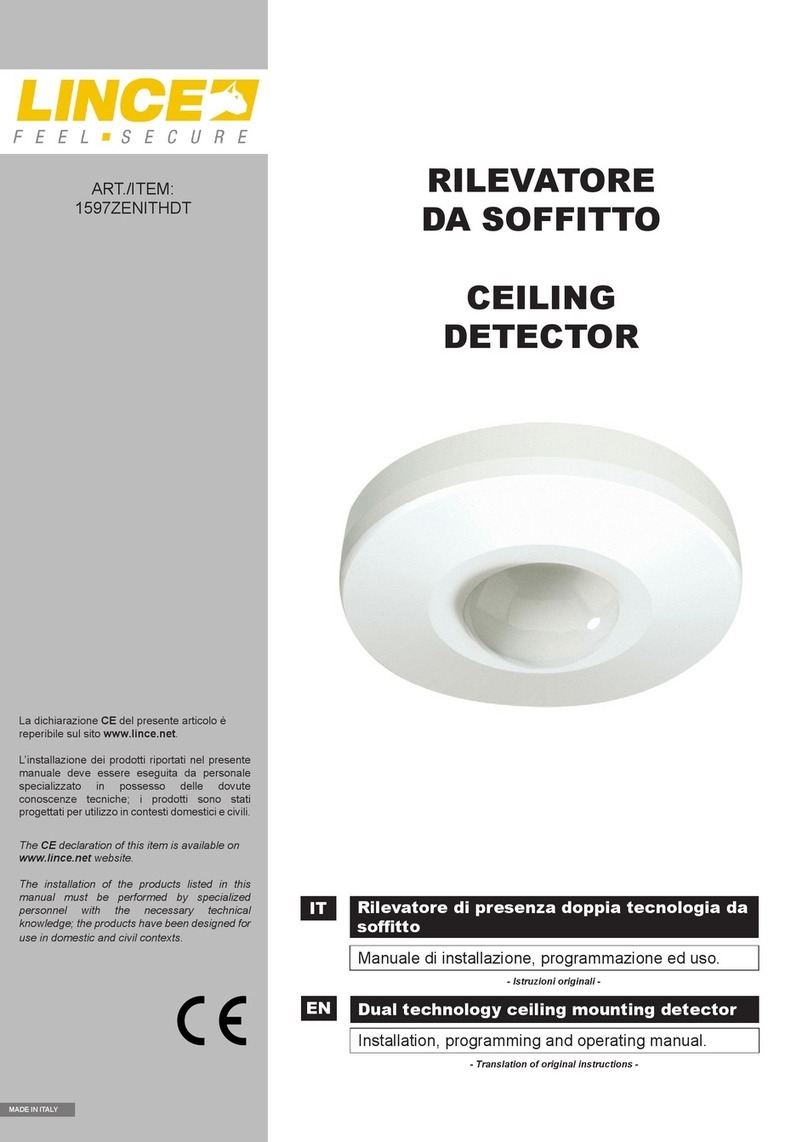
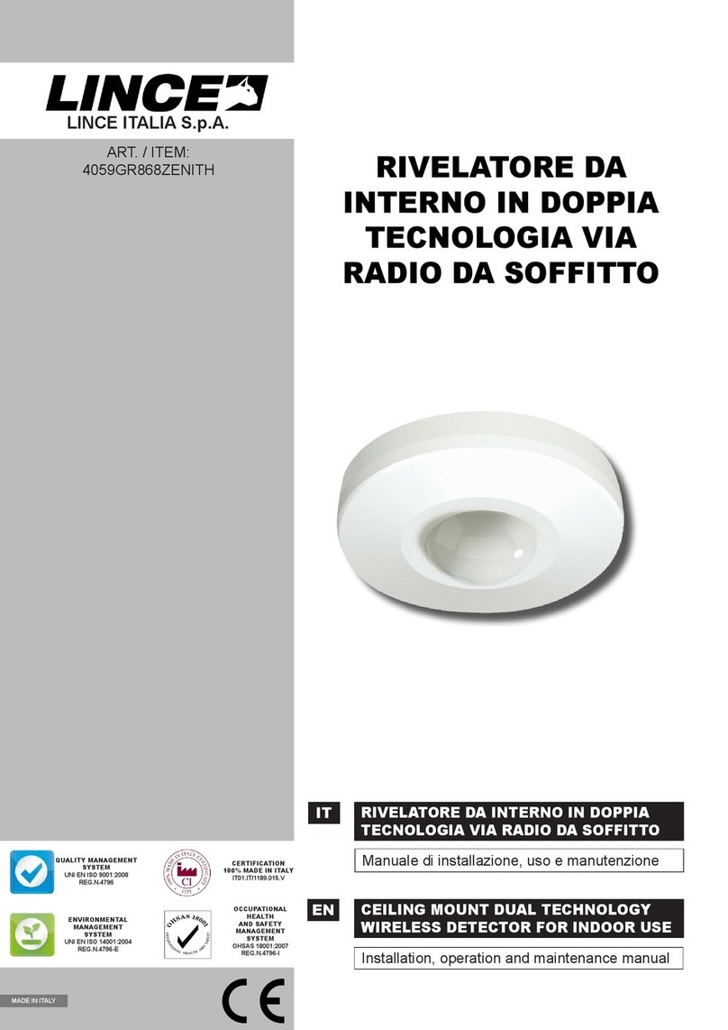
  9. Lince ZENITH IR User manual

Lince ZENITH IR User manual

IT RILEVATORE INFRAROSSO PASSIVO DA
SOFFITTO
Manuale di installazione, programmazione ed uso.
- Istruzioni originali -
EN CEILING MOUNT PASSIVE INFRARED
DETECTOR
Installation, programming and operating manual.
- Translation of original instructions -
LINCE ITALIA S.p.A.
ART./ITEM:
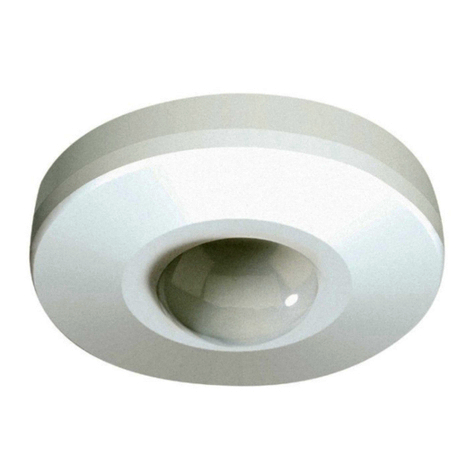
1596ZENITHIR
ZENITH IR
REG.N.4796
UNI EN ISO 9001:2008
MADE IN ITALY
LINCE ITALIA S.p.A.
2
Fig. 1
CARATTERISTICHE GENERALI
I rilevatori ad infrarossi passivi sono una valida alternativa ad
altri tipi di sensori quali: microonde ultrasuoni infrarossi attivi, etc.
che talvolta non possono essere usati per problemi ambientali
o di consumo. Il rilevatore ZENITH IR ha un basso consumo di
corrente, lavora con un ampia gamma di tensioni di ingresso,
ammette un ampio fattore di ripple ed un alta immunità ai disturbi
esterni, elettrici o ambientali. La protezione dell’ambiente,
avviene mediante la rilevazione di rapidi cambiamenti di livello di
energia infrarossa presente nell’ambiente, causati da intrusioni.
Tutto ciò senza emissione di alcuna radiazione. La particolare
installazione a softto garantisce una ottima copertura in tutte le
applicazioni no a softti con altezza di 8/10 metri.
CARATTERISTICHE TECNICHE
Alimentazione 10-15 Vcc
Tecnologia
di rilevazione IR passivo
Assorbimento 6 mA
Relè Allarme contatto N.C.
Tamper contatto N.C.
Copertura 360°
Peso 100 g
Dimensioni ø 129 x 43 mm
INSTALLAZIONE
Lo ZENITH IR offre prestazioni ottimali ed una elevata immunità
contro i falsi allarmi.
Evitare tuttavia di installare il rilevatore in luoghi soggetti a
repentini sbalzi termici; é buona norma evitare che i raggi
solari colpiscano direttamente il sensore, è inoltre sconsigliata
l’installazione in zone con elevate correnti d’aria.
L’installazione del rilevatore è unicamente da softto. Si consiglia
di seguire le seguenti istruzioni:
- Individuare il punto del softto più indicata al ne di rilevare
eventuali intrusi, attenendosi al graco di copertura riportato
in fondo al presente manuale (maggiore è l’altezza del softto
maggiore sarà l’area protetta).
- Eventuali irregolarità del softto non sono da considerarsi un
problema per il ssaggio, in quanto, in prossimità dei fori di
ssaggio sono state previste delle alette che permettono di
adattare la base alle irregolarità del piano di ssaggio.
Per il ssaggio agire come segue (g.
1):
• ruotare la copertura in senso
orario (Opened) ed estrarla dal
suo alloggiamento;
• effettuare i collegamenti come di
seguito indicati.
• A ne operazione, riposizionare
la copertura precedentemente
rimossa e ruotarla no a far
coincidere la tacca di riferimento
(Closed).
REGOLAZIONE PORTATA
Non è prevista nessuna regolazione della portata.
L’installazione esclusivamente da softto, non presenta il
problema della distanza in quanto i fasci (vedi COPERTURA)
giungeranno no al pavimento e non oltre.
GENERAL FEATURES
Passive infrared detectors are a valid alternative to other types
of sensors such as: microwave, ultrasound, infrared, active,
etc. which often cannot be used due to environmental or
consumption problems. The ZENITH IR detector has low energy
consumption, works with a wide range of input voltages, admits
a wide ripple factor and high level immunity to external, electrical
or environmental interferences. Environmental protection is
implemented by the detection of quick changes of the infrared
energy level present in the environment caused by intrusions.
All without the emission of radiation. The particular ceiling
installation guarantees a high level of coverage in all applications
up to ceilings 8/10 meters high.
TECHNICAL FEATURES
Power supply 10-15 Vcc
Detection
technology Passive IR
Absorption 6 mA
Alarm Relay N.C. contact
Tamper N.C. contact
Range 360°
Weight 100 g
Dimensions ø 129 x 43 mm
INSTALLATION
ZENITH IR offers optimal performance and high false alarm
immunity.
Nonetheless, do not install the detector in places subject to
sudden thermal changes. It is good practice to prevent solar rays
from directly hitting the sensor. It is also ill-advised to install the
sensor in areas with high air currents.
The detector must only be installed on the ceiling. It is
recommended to follow these instructions:
-Locate the most suitable point of the ceiling in order to detect
any intruders, adhering to the range chart at the end of this
manual (the higher the ceiling, the wider the protected area).
-Any ceiling unevenness should not be considered as a problem
for fastening, since ns are provided near the fastening holes
to adapt the base to fastening surface unevenness.
For fastening, do as follows (g.
1):
• turn the cover clockwise
(Opened) and remove it
from its housing;
• perform the connections as
indicated below.
• When the operation is
nished, put the cover
back in place and turn it to
match the reference notch
(Closed).
RANGE ADJUSTMENT
No range adjustment is foreseen.
As it is only installed on the ceiling, there is no problem regarding
distance as the beams (see COVERAGE) reach the oor and not
beyond.
3
LINCE ITALIA S.p.A.
Fig. 2
Fig. 3
COLLEGAMENTI
I collegamenti con il sensore ZENITH IR devono essere effettuati
con cavo schermato: collegare lo schermo alla massa della
centrale lasciandolo scollegato dalla parte del sensore. Se la
distanza tra il sensore e la centrale è notevole, assicurarsi che
non vi sia caduta di tensione. Per la descrizione dei morsetti fare
riferimento alla seguente tabella:
+/- Morsetti di alimentazione 12V, 6 mA.
Quando il sensore viene alimentato impiega circa 60”
per stabilizzarsi.
A.S. Contatti del relé di allarme.
Normalmente Chiuso: collegare ad una linea di allarme.
N.C. Contatti dello switch antisabotaggio.
Normalmente chiuso: collegare alla serie dell’antisabo-
taggio.
W. T. Morsetto per l’esclusione a distanza dei LED di allarme,
leggere il paragrafo “esclusione LED di allarme”.
ESCLUSIONE LED DI ALLARME
Il morsetto WT consente di escludere a distanza il LED, ed il
relé di allarme. Se si vuole che il LED di allarme non segnali
i movimenti rilevati a centrale disinserita, si deve inviare un
positivo sul questo morsetto quando l’impianto è disinserito.
È possibile escludere in modo permanente il LED, rimuovendo il
jumper LED OFF presente sulla scheda (v. g. 2).
COPERTURA
L’area di copertura è di circa 360° come riportato in g. 3.
Jumper LED/OFF per esclusione LED
Vista laterale
Vista dall’alto
CONNECTIONS
Connections with the ZENITH IR sensor must be performed with
shielded cable: connect the exposed conductive part of the shield
to the control panel, leaving it disconnected on the sensor side. If
the distance between the sensor and control panel is signicant,
ensure there is no voltage drop. Refer to the following table for a
description of terminal blocks:
+/- Power terminal blocks 12V, 6 mA.
When the sensor is powered, it takes about 60” to
stabilise.
A.S. Alarm relay contacts.
Normally closed: connect to an alarm line.
N.C. Contacts of anti-tamper switch.
Normally closed: connect to the anti-tamper series.
W. T. Terminal block for remote exclusion of alarm LED’s.
Read the paragraph “alarm LED exclusion”.
ALARM LED EXCLUSION
The WT terminal block allows you to remotely exclude the LED and
the alarm relay. If you do not want the alarm LED to signal movements
detected with the control panel disarmed, a positive signal must be
sent to this terminal block when the system is disarmed.
The LED can be excluded permanently by removing the LED
OFF jumper on the board (see g. 2).
COVERING
The coverage area is approximately 360° as displayed in g. 3.
LED/OFF jumper to exclude the LED
Side view
Top view
001530/00762AB Rev1
LINCE ITALIA S.p.A
Via Variante di Cancelliera, snc
00040 ARICCIA (Roma)
Tel. +39 06 9301801
Fax +39 06 930180232
[email protected] www.lince.net

This manual suits for next models

1

Other Lince Security Sensor manuals

Lince GR868 Bobby User manual

Lince

Lince GR868 Bobby User manual

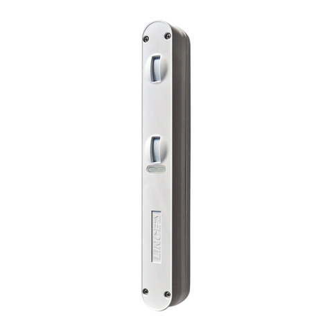
Lince ZENITH GOLD 869 Series User manual

Lince

Lince ZENITH GOLD 869 Series User manual

Lince OBLO'/E User manual

Lince

Lince OBLO'/E User manual

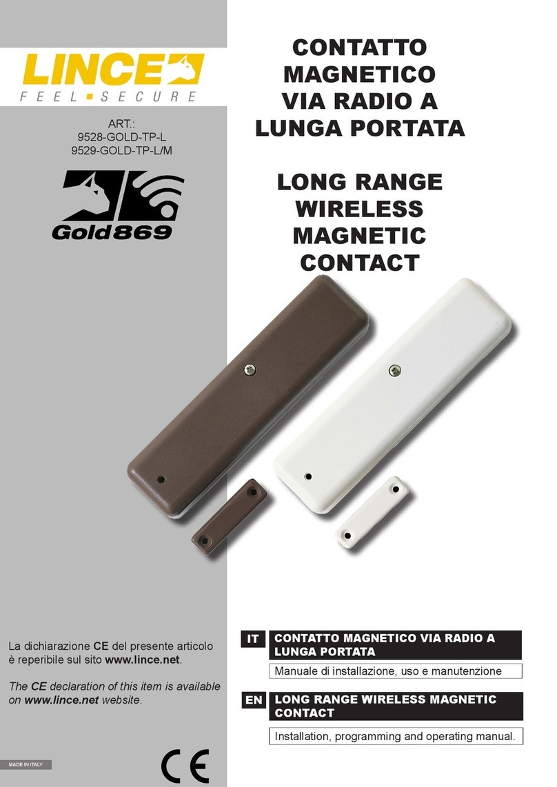
Lince 9528-GOLD-TP-L User manual

Lince

Lince 9528-GOLD-TP-L User manual

Lince 1871BOBBY/E User manual

Lince

Lince 1871BOBBY/E User manual

Lince Bobby User manual

Lince

Lince Bobby User manual

Lince 1947-BOBBY180-E-AM User manual

Lince

Lince 1947-BOBBY180-E-AM User manual

Lince 1866BABY-BA/E User manual

Lince

Lince 1866BABY-BA/E User manual

Lince BOBBY-AM/E User manual

Lince

Lince BOBBY-AM/E User manual

Lince 1534JOLLY User manual

Lince

Lince 1534JOLLY User manual

Lince BABY BA User manual

Lince

Lince BABY BA User manual

Lince DTP 20 User manual

Lince

Lince DTP 20 User manual

Lince GR868 Bobby User manual

Lince

Lince GR868 Bobby User manual

Lince BABY User manual

Lince

Lince BABY User manual

Lince 1673BOBBY User manual

Lince

Lince 1673BOBBY User manual

Lince ZENITH GOLD 869 Series User manual

Lince

Lince ZENITH GOLD 869 Series User manual

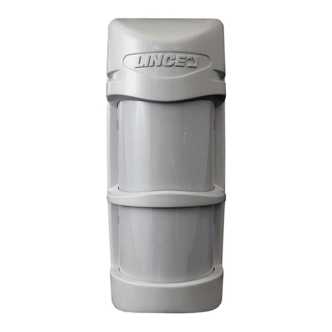
Lince 1883 ZENITH DT/E User manual

Lince

Lince 1883 ZENITH DT/E User manual

Lince ZENITH GOLD 869 Series User manual

Lince

Lince ZENITH GOLD 869 Series User manual

Lince Bobby User manual

Lince

Lince Bobby User manual

Lince Bobby Universale User manual

Lince

Lince Bobby Universale User manual

Lince 1630DT/JOLLY User manual

Lince

Lince 1630DT/JOLLY User manual

Lince 1926BOBBY-T-AM/U User manual

Lince

Lince 1926BOBBY-T-AM/U User manual

Lince 9504-GOLD-DT User manual

Lince

Lince 9504-GOLD-DT User manual

Lince GR868 Bobby User manual

Lince

Lince GR868 Bobby User manual

Popular Security Sensor manuals by other brands

Halma BEA IXIO-DO1 I quick start guide

Halma

Halma BEA IXIO-DO1 I quick start guide

Siemens Sinteso FD20 Product data

Siemens

Siemens Sinteso FD20 Product data

System Sensor 9440X FAAST Installation and maintenance instructions

System Sensor

System Sensor 9440X FAAST Installation and maintenance instructions

Argus Security Taurus TW-DT-01/BL manual

Argus Security

Argus Security Taurus TW-DT-01/BL manual

Interlogix DD300-P Series Installation sheet

Interlogix

Interlogix DD300-P Series Installation sheet

Eaton 2450 Series manual

Eaton

Eaton 2450 Series manual

elock EL-PB60S manual

elock

elock EL-PB60S manual

Orno OR-CR-209 operating manual

Orno

Orno OR-CR-209 operating manual

Omron ZX-L-N manual

Omron

Omron ZX-L-N manual

ADEMCO 5808C installation instructions

ADEMCO

ADEMCO 5808C installation instructions

Draminski PREGNANCY DETECTOR manual

Draminski

Draminski PREGNANCY DETECTOR manual

Onicon Air Monitor VOLU-probe/1SS installation instructions

Onicon

Onicon Air Monitor VOLU-probe/1SS installation instructions

Grasslin talis PFM 360-6-1 operating manual

Grasslin

Grasslin talis PFM 360-6-1 operating manual

System Sensor B401R Installation and maintenance instructions

System Sensor

System Sensor B401R Installation and maintenance instructions

Infinite L-COM SRCN-C412-2 user guide

Infinite

Infinite L-COM SRCN-C412-2 user guide

Petzl Tandem Speed P21SPE manual

Petzl

Petzl Tandem Speed P21SPE manual

C.P. Electronics MWS1A-C-IP-PRM-VFC installation guide

C.P. Electronics

C.P. Electronics MWS1A-C-IP-PRM-VFC installation guide

HIK VISION DS-PDD12P-EG2-WE manual

HIK VISION

HIK VISION DS-PDD12P-EG2-WE manual

manuals.online logo
manuals.online logoBrands
  • About & Mission
  • Contact us
  • Privacy Policy
  • Terms and Conditions

Copyright 2025 Manuals.Online. All Rights Reserved.