Lincoln DU1 User manual

LINCOLN GmbH • Postfach 1263 • D-69183 Walldorf • Tel +49 (6227) 33-0 • Fax +49 (6227) 33-259 • Tx 466088
User’s Manual
Operating Instructions
Page 1 of 12
1.3A-18001-A96
Subject to change without notice
1186a96
Pressure-Controlled Change-Over Valve
Model DU1

LINCOLN GmbH • Postfach 1263 • D-69183 Walldorf • Tel +49 (6227) 33-0 • Fax +49 (6227) 33-259 •Tx 466088
Page 2 of12
User’s Manual
Operating Instructions
1.3A-18001-A96
Subject to change without notice
Table of Contents
Page
Operating instructions............................................................... 7
Start-up................................................................................ 7
Maintance and repair .......................................................... 7
Setting.................................................................................. 7
Troubleshooting......................................................................... 8
Dimensioned drawing ............................................................... 9
Spare parts drawing................................................................ 11
Spare parts list ........................................................................ 12
Page
Safety Instructions .................................................................... 3
Technical data ........................................................................... 3
Application ........................................................................... 3
Structure and operation ...................................................... 3
Electric equipment .............................................................. 6
Installation of the change-over valve.................................. 6
Electric connection.............................................................. 6

LINCOLN GmbH • Postfach 1263 • D-69183 Walldorf • Tel +49 (6227) 33-0 • Fax +49 (6227) 33-259 • Tx 466088
User’s Manual
Operating Instructions
Page 3 of 12
1.3A-18001-A96
Subject to change without notice
The User’s Manual as well as the Safety Instructions must be
read by the operating and maintenance personnel before any
intervention is undertaken at the change-over valve. They must
be available on the site where the change-over valve is in opera-
tion.
The change-over valve model DU-1 is exclusively designed for
use in two-line centralized lubrication systems.
The maximum ratings mentioned in the Technical Data, particu-
larly the operating pressure of 350 bar, must on no account be
exceeded.
Any other use is not in accordance with the specified instruc-
tions.
Safety Instructions
The manufacturer is not liable for damages resulting from an
improper use.
Alteration or modifications of the change-over valve are only al-
lowed if approved by the manufacturer.
For repairs use only original spare parts. If other spare parts
are used, the manufacturer may be released from its liability for
the resulting consequences.
The change-over valve should only be used if it is in good tech-
nical condition. Defects and faults which may impair its operati-
on and safety must be remedied immediately.
If you need more information than is given in this User’s Manu-
al, please contact our company (see address below).
Technical Data
Flow rate: ......................................................... max. 14 dm³/h
Change-over pressure: ................................... min. 140 bar
......................................................................... max. 350 bar
Factory setting:................................................ 170 bar
Operating pressure: ........................................ max. 350 bar
Threaded connection: ..................................... G 1/2 i.
Dispensed media: ........................................... Lubricating oils
......................................................................... from 60 cSt on-
......................................................................... wards at +40°C
......................................................................... Greases up to
......................................................................... NLGI-grade 3
(depending on
operating tempe-
rature)
Operating temperature:.............................. - 20 ° C to + 80°C
Mounting position: ...................................... variable
Position switch:
Nominal circuit voltage:.............................. 500 V, 25-60 Hz
Continuous current:.................................... 10 A
Operating current: ...................................... 4 A
Type of protection:...................................... IP 67
further technical details:............................. refer to Data sheet
.................................................................... 93G-10001-A95
Application
The model DU-1 pressure-controlled change-over valve is desi-
gned for use in two-line lubrication systems operating within the
above specified pressure range and flow rate. These systems
include the central lubrication pumps model ZPU 08/14, ZPU
01/02, HJ 2 and ZPU 75.
For values exceeding the mentioned ranges, one can use the
electric motor-operated change-over valve model EM-U2 in con-
junction with end-of-line pressure switches.
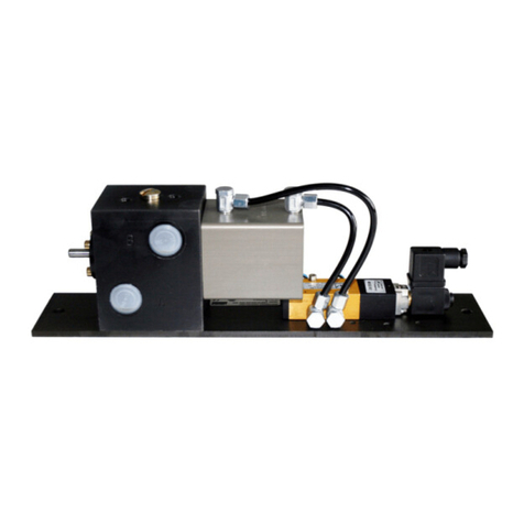
The model DU1 change-over is available in three versions:
Model Part. No.
DU1-G mounted on base plate 617-28683-1
DU1-GK with indicator pin, mounted on
base plate 617-28619-1
DU1-GKS with indicator pin and limit switch,
mounted on base plate 617-28620-1
Structure and Operation
The principle of operation of the change-over valve is similar to
that of a 4/2-way valve which alternately discharges the lubri-
cant fed by the pump into one of the two main lines while the
other main line is connected to the return line connection of the
pump.
The figures 1 and 2 show a schematic illustration of the operati-
on of the DU-1 change-over valve. The lines marked in black
represent the pressure lines and the white lines the pressure
relief lines.
line under pressure
line relieved
control lubricant
LINCOLN GmbH • Postfach 1263 • D-69183 Walldorf • Tel +49 (6227) 33-0 • Fax +49 (6227) 33-259 •Tx 466088
Page 4 of12
User’s Manual
Operating Instructions
1.3A-18001-A96
Subject to change without notice
4089a96
Fig.1: operation of change-over valve DU1
two-line metering devices and half of the lubrication points are
supplied with dosed lubricant quantities. Once all the pistons in
the metering devices have reached their final position the pres-
sure increases in the main line (7), in the DU-1 change-over
valve and in the pressure line (5) until it overcomes the force of
the spring which presses down the valve piston (4). The spring
force and thus the change-over pressure can be adjusted by
means of the adjusting screw (9).
The central lubrication pump supplies the lubricant to the chan-
ge-over valve via the pressure line (5). The lubricant travels to
the lubricant metering devices via the preselecting piston (2),
the change-over piston (1) and the main line (7), while the main
line (8) is connected to the reservoir of the central lubrication
pump via the pressure relief line (6) and is thus pressureless
(see Fig. 1).
The lubricant pressure triggers the pistons of the connected

LINCOLN GmbH • Postfach 1263 • D-69183 Walldorf • Tel +49 (6227) 33-0 • Fax +49 (6227) 33-259 • Tx 466088
User’s Manual
Operating Instructions
Page 5 of 12
1.3A-18001-A96
Subject to change without notice
Now, the valve piston (4) opens the connection between the
pressure line (5) and the preselecting piston (2) via the change-
over piston (3). The preselecting piston (2) is pushed upwards to
make the connection between the pressure line (5) and the up-
per face of the change-over piston (1).
The change-over piston is pushed downwards, thus opening the
connection between the pressure line (5) and the main line (8),
while the main line (7) is simultaneously connected to the reser-
voir of the central lubrication pump via the pressure relief line
(6). The lubricant in the main line (7) can be relieved.
The pressure rising in the main line (8) pushes up the change-
over piston (3)(Fig. 2).
The process described above is repeated for the main line (8).
Fig.2: operation of change-over valve DU1
4089b96

LINCOLN GmbH • Postfach 1263 • D-69183 Walldorf • Tel +49 (6227) 33-0 • Fax +49 (6227) 33-259 •Tx 466088
Page 6 of12
User’s Manual
Operating Instructions
1.3A-18001-A96
Subject to change without notice
Electric Equipement
Position switch
:
technical details refer to leaflet 93A-10001-A95
Installation of the change-over valve
Installation site requirements
• Even, solid and vibration-free surface of installation
• Protected from dust and dirt
• Safe from atmospheric influences
Electric Connection
Before connecting the change-over valve, disconnect the sy-
stem from the power supply.
The installation and connection of electric
devices should be carried out only by qua
lified personnel!
Observe the relevant technical aspects
and the respective legislation relative to
industrial protection regulations (instruc-
tions, standards).
Electric connection of the position switch
• In accordance with the electric wiring diagram
Mounting position: Variable
The tube line between the pump and the
change-over valve should be at least 2 m

LINCOLN GmbH • Postfach 1263 • D-69183 Walldorf • Tel +49 (6227) 33-0 • Fax +49 (6227) 33-259 • Tx 466088
User’s Manual
Operating Instructions
Page 7 of 12
1.3A-18001-A96
Subject to change without notice
Repairs should be carried out only by qualified personnel using
original spare parts.
Provided that the pump dispenses only clean lubricant, the
change-over valve does not need any particular maintenance.
The change-over pistons and valve pistons are subject to a na-
tural wear which depends on the operating time and adjusted
pressure.
The pistons are fitted with high precision and, therefore, they
are not replaceable. In case of repairs the complete change-
over valve housing must be replaced.
Operating Instructions
Start-up
After the tube lines have been connected the change-over valve
is ready for operation.
Maintenance and Repair
Before undertaking any repair on the change-over valve, obser-
ve the following instructions:
1. Disconnect the system from the power
supply, switch the pump drive motor off
and make sure that it cannot be restar-
ted in advertently.
2. Disconnect the tube fittings of the
change-over valve in order to educe
the pump and system pressure to zero
(read the pressure gauge).
Caution: Danger due to splashing
lubricant.
Setting
Setting of the change-over pressure:
Factory setting: 170 bar
To increase the change-over pressure (refer to the Spare Parts
List, items 11 and 12):
• Unscrew the counter nut.
• Turn the adjusting screw clockwise until the desired pressure
is reached (max. 350 bar)
• Tighten the counter nut in order to maintain the new setting.
To decrease the change-over pressure:
• Unscrew the counter nut.
• Turn the adjusting screw counterclockwise until the desired
pressure is reached (min. 140 bar)
• Tighten the counter nut in order to maintain the new setting.
Attention: The change-over pressure
should not be higher than the maximum
system pressure.
Note: The change-over pressure must always be higher than
the actuating pressure of the two-line metering devices. In order
to have a safety margin, set the change-over pressure in such a
way that it is 30 bar higher than the actuating pressure of the last
metering device installed in the system.

LINCOLN GmbH • Postfach 1263 • D-69183 Walldorf • Tel +49 (6227) 33-0 • Fax +49 (6227) 33-259 •Tx 466088
Page 8 of12
User’s Manual
Operating Instructions
1.3A-18001-A96
Subject to change without notice
For all defects, first check whether the pump is operating with the full pressure.
•Fault: The change-over valve does not switch over - No pressure rise in the system
•Cause •Remedy
• Change-over piston worn • piston worn
Note: The lubricant is supplied to the pump via the return
line connection.
•Fault: The change-over valve does not switch over - Lubricant leaks at the pump safety valve
•Cause •Remedy
• Change-over piston blocked by foreign particles • Disassemble the change-over valve and clean it.
Attention: Do not interchange the pistons.
If there is any damage to the piston replace the complete
change-over valve.
•Fault: No signal of the position switch is transmitted to the electric control unit
•Cause •Remedy
• Position switch defective • Check the position switch and the electric connections,
replace the switch
•Fault: The change-over valve switches over prematurely or too quickly
•Cause •Remedy
• Adusted change-over pressure too low • Increase the change-over pressure
• Valve piston or packing of valve bushing worn • Replace the bushing with the valve piston
(Item 9 Spare Parts List)
• Valve spring broken • Replace the valve spring (Item 13 Spare Parts List)
Troubleshooting

LINCOLN GmbH • Postfach 1263 • D-69183 Walldorf • Tel +49 (6227) 33-0 • Fax +49 (6227) 33-259 • Tx 466088
User’s Manual
Operating Instructions
Page 9 of 12
1.3A-18001-A96
Subject to change without notice
Fig.3: Model DU1-GK (p.no.615-28619-1) change-over valve with indicator pin, mounted on base plate
4090a96
Dimensioned drawing

LINCOLN GmbH • Postfach 1263 • D-69183 Walldorf • Tel +49 (6227) 33-0 • Fax +49 (6227) 33-259 •Tx 466088
Page 10 of12
User’s Manual
Operating Instructions
1.3A-18001-A96
Subject to change without notice
Fig.4: Model DU1-GKS (p.no.617-28620-1) change-over valve with position switch, mounted on base plate
4090b96

LINCOLN GmbH • Postfach 1263 • D-69183 Walldorf • Tel +49 (6227) 33-0 • Fax +49 (6227) 33-259 • Tx 466088
User’s Manual
Operating Instructions
Page 11 of 12
1.3A-18001-A96
Subject to change without notice
Fig.5: Spare parts drawing
Spare Parts Drawing

LINCOLN GmbH • Postfach 1263 • D-69183 Walldorf • Tel +49 (6227) 33-0 • Fax +49 (6227) 33-259 •Tx 466088
Page 12 of12
User’s Manual
Operating Instructions
1.3A-18001-A96
Subject to change without notice
Item. Designation Qty. Part-no..
1 Change-over valve housing assy.
with pin (DU1-GK and GKS) 1 517-32043-1
Change-over valve housing
without pin (DU1-G) 1 517-32044-1
2 Closure plug with borehole
6kt G1/4 5 303-19666-1
3 Closure plug without borehole 1 417-24361-1
4 Indicator pin 1 301-17341-1
5 Sealing ring 2,8x7x1,5 1 306-17800-1
6 U-cup sealing ring 3x7x5x3,5 1 220-12234-1
7 O-ring 10 x 1,5 6 219-12223-3
8 O-ring 12,3 x 2,4 1 219-12451-1
9 O-ring 20,3 x 2,4 1 219-12451-2
10 Bushing with valve piston 1 517-32042-1
11 Hexagon nut M 10 C 1 207-12136-1
12 Hexagon head screw M 10 x 35 C1 200-12008-6
13 Thrust piece 1 417-21034-2
14 Compression spring 1 300-17223-1
15 Spring sleeve 1 417-21033-1
16 Base plate 1 307-19631-1
only for valid change-over
valve model DU1-GKS:
17 Bracket 1 307-19630-1
18 Position switch 1 236-13262-4
19 Hexagon socket head screw
M 5 x 40 C 2 201-12594-2
20 Washer A 5,3 C 2 209-13077-3
21 Hexagon socket head screw
M 5 x 20 C 2 201-12016-8
22 Flat head screw with hexagon
socket M 6 x 20 C 4 202-12049-6
Spare Parts List
Table of contents
Other Lincoln Control Unit manuals

Lincoln
Lincoln 877 User manual

Lincoln
Lincoln A Series User manual

Lincoln
Lincoln SKF 85307 User manual

Lincoln
Lincoln A Series User manual

Lincoln
Lincoln 3866 User manual

Lincoln
Lincoln SKF IG502-2-E User manual

Lincoln
Lincoln POWER-MASTER III 84981 Owner's manual

Lincoln
Lincoln 881 Product manual

Lincoln
Lincoln 85660 User manual

Lincoln
Lincoln B Series User manual