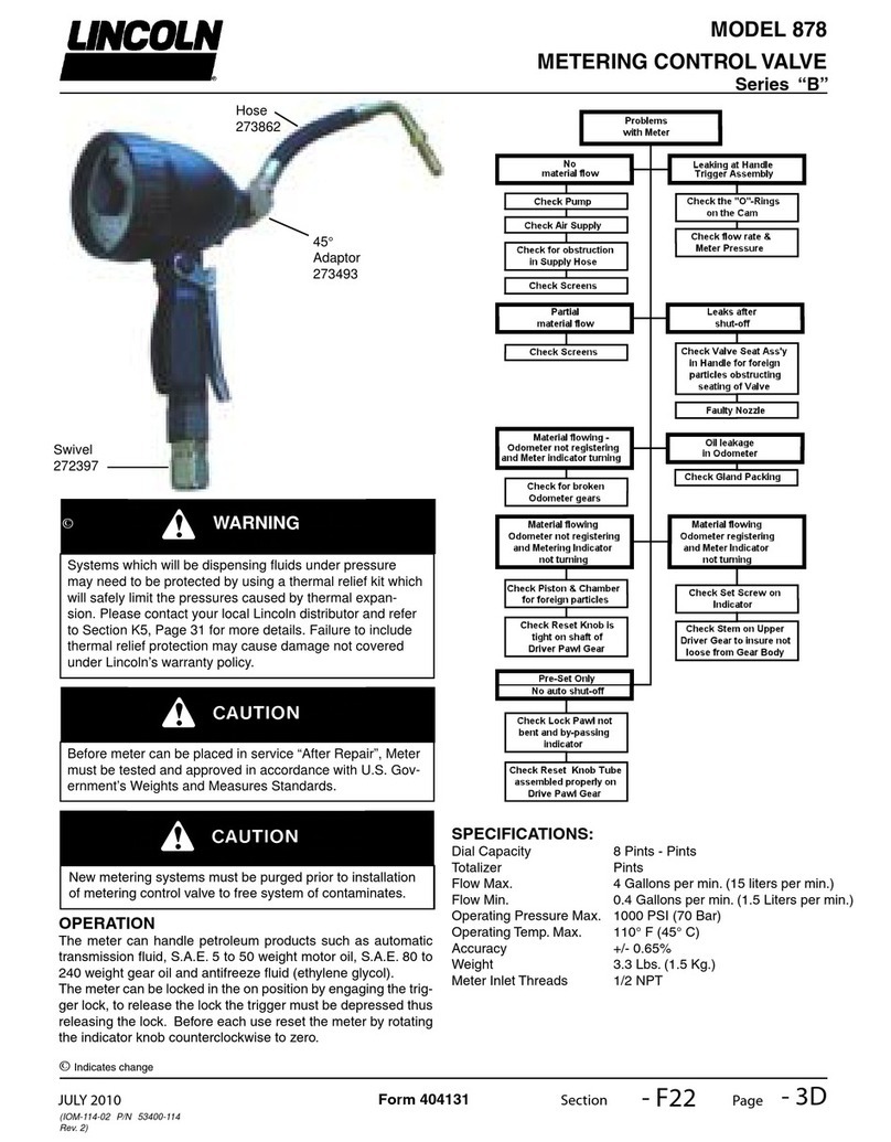
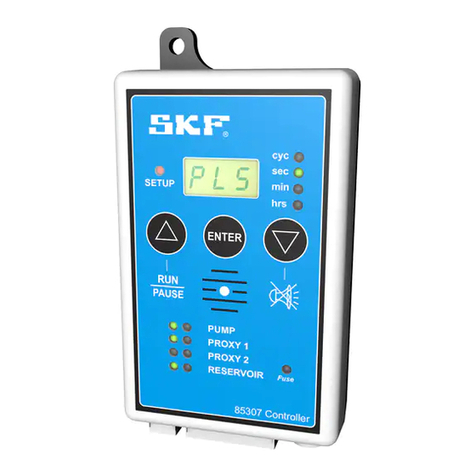
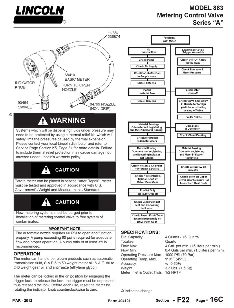
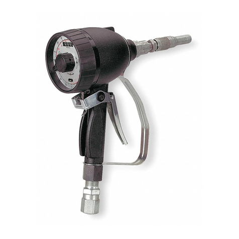
Lincoln POWER-MASTER III 84981 Owner's manual

©
© Indicates change
Page
Section - A50 - 80A
Form 403663
MAY - 2007
Models 84981, 84982, 84983, 84984, 84985
POWER-MASTER III DRUM PUMPS
Ball Type Foot Valve
OWNER/OPERATOR MANUAL
It is the responsibility of the Owner/Operator to properly use and maintain this equipment.
The Instructions and Warnings contained in this manual shall be read and understood by the Owner/Operator prior to operating
this equipment
It is the responsibility of the Owner/Operator to maintain the legibility of all Warning and Instruction labels
The Owner/Operator shall retain this manual for future reference to important Warnings, Operating and Maintenance
Instructions.
DO NOT operate these pumps with 10” airmotor.
DO NOT exceed the stated maximum working pressure of the airmotor or the
lowest rated component in your system.
DO NOT alter or modify any part of this equipment.
DO NOT operate this equipment with combustible gas.
DO NOT attempt to repair or disassemble the equipment while the system is
pressurized.
TIGHTEN all uid connections securely before using this equipment.
ALWAYS read and follow the uid manufacturer’s recommendations regarding
uid compatibility, and the use of protective clothing and equipment.
CHECK all equipment regularly and repair or replace worn or damaged parts
immediately.
IMPORTANT: Failure to heed these warnings including misuse, over pressur-
izing, modifying parts, using incompatible chemicals and uids, or using worn or
damaged parts, may result in equipment damage and/or serious personal injury,
re, explosion, or property damage.
MODEL CHART
PUMP PUMP MAXIMUM DELIVERY MAXIMUM AIR DIMENSION "A" DIMENSION "B"
TUBE MODEL AIRMOTOR* RATIO PRESSURE PRESSURE in. (cm.) in. (cm.)
2061 84808 42:1 4200 psi (294 bar) 100 psi (7 bar) 60 (152.4)
34 (86.4)
2021 84806 24:1 2400 psi (168 bar)
84985 2001 84804 12:1 2400 psi (168 bar) 200 psi (14 bar) 60-7/8 (154.6)
2052 84803 6:1 1200 psi (84 bar)
2065 84808 42:1 4200 psi (294 bar) 100 psi (7 bar) 53-3/8 (135.6)
273/8 (69.5)
2025 84806 24:1 2400 psi (168 bar)
84984 2005 84804 12:1 2400 psi (168 bar) 200 psi (14 bar) 54-1 /4 (137.8)
2055 84803 6:1 1200 psi (84 bar)
2061-7 84808 42:1 4200 psi (294 bar) 100 psi (7 bar) 60 (152.4)
34 (86.4)
2021-7 84806 24:1 2400 psi (168 bar)
84983 2001-7 84804 12:1 2400 psi (168 bar) 200 psi (14 bar) 60-7/8 (154.6)
2052-7 84803 6:1 1200 psi (84 bar)
2061-8 84808 42:1 4200 psi (294 bar) 100 psi (7 bar) 60 (152.4)
2021-8 84806 24:1 2400 psi (168 bar)
84982 2001-8 84804 12:1 2400 psi (168 bar) 200 psi (14 bar) 60-7/8 (154.6)
2052 -8 84803 6:1 1200 psi (84 bar)
2061-9 84808 42:1 4200 psi (294 bar) 100 psi (7 bar) 60 (152.4)
2021-9 84806 24:1 2400 psi (168 bar)
84981 2001-9 84804 12:1 2400 psi (168 bar) 200 psi (14 bar) 60-7/8 (154.6)
2052-9 84803 6:1 1200 psi (84 bar)
* Refer to Airmotor Owner/Operator Manual, Section AS Page 78.

Page Number - 2
Models 84981, 84982, 84983, 84984, 84985
POWER-MASTER III DRUM PUMPS
Ball Type Foot Valve
Form 403663
ATTACHING AIRMOTOR TO
PUMPTUBE
1. Tightly attach tie rods to the airmotor
(use short threaded end of the tie rods).
2. Mount airmotor on top of the pump tube
outlet and tightly connect Coupling Nut
(Item 2) to airmotor piston rod.
3. Hand tighten tie rods to the pumptube
with four nuts supplied with airmotor.
4. Slowly cycle the pump several times,
using just enough air pressure to operate
the pump without stalling.
5. Stop the pump on an “up” stroke and
tighten the four nuts to securely fasten
the airmotor to the pumptube.
OPERATING PRECAUTIONS
Use Lincoln replacement parts to assure•
compatible pressure rating
HEED ALL WARNINGS•
Be sure material hoses and other•
components are able to withstand uid
pressures developed by this pump
Do not operate pump continuously at•
speeds in excess of 75 cycles per
minute.
Disconnect air line from pump air motor•
when system sits idle for long periods of
time.
SERVICING Before servicing or •
cleaning pump, or removing uid hose or
gun from a unit that has been used, be
sure to disconnect air lines and carefully
bleed pressure off of the system.
PREVENT STATIC SPARKING. If static
sparking occurs, re or explosion could
result. Pump, dispensing valve, and con-
tainers must be grounded when handling
ammable uids such as petroleum prod-
ucts, paints, lacquers, etc. and wherever
discharge of static electricity is hazard.
Check continuity (a good static wire•
connection) with an ohmmeter Place
one probe on one hose tting and the
other probe on other hose tting, conti-
nuity or proper grounding through hose
is good when a reading is obtained on
the ohmmeter
PREVENT FIRES. When pumping, •
ushing or recirculating volatile sol-
vents, the area must be adequately
ventilated.
Keep solvents away from heat, sparks •
and open ames. Keep containers
closed when not in use.
DO NOT allow pump to operate when
out of material.
PUMP PRIMING
To begin operation, the pump has to
be primed with the pumped material.
The Power-Master III pump is a double
acting (pumps material on ‘up’& “down”
stroke.) positive displacement recipro-
cating pump and as such intakes mate-
rial only on the “up” stroke.
To prime pump, open output line (material
valve) and slowly open air supply valve
until pump starts. Allow pump to cycle
very slowly until all air is pushed out of
lines and material lls up pump and lines.
Close output line (material shut-off valve)
- pump should stall against pressure
Note: Pumps are factory tested with light
oil and some of it is left in to protect pump
parts during storage and transportation.
To prevent contamination of material to be
pumped, ush pump before using.

Page Number - 3
Models 84981, 84982, 84983, 84984, 84985
POWER-MASTER III DRUM PUMPS
Ball Type Foot Valve
Form 403663
DISASSEMBLY
Tools Required
2-1/8” Dia Strap Wrench 7/8” Hex Wrench 2-1/4” Hex Wrench
1-3/8” Hex Wrench
Retaining Ring Pliers (Internal) 5/8” Hex Wrench
1” Hex Wrench
Procedure
1. Remove Foot Valve Body (Item 36) from Bushing Tube
(Item 34).
2. Slide Retaining Pin (Item 37) from Foot Valve Body (Item
36) and remove Ball (Item 35).
3 Unscrew Bushing Tube (Item 34) and slide off of Piston
(Item 23).
4. Remove Bolt Connector (Item 1) from Plunger (Item 3)
5. Pull Piston (Item 23) to remove Plunger (Item 3), Connect-
ing Rod (Item 18) and Piston Assembly from Pump Tube
(Item 17).
6. Remove Pump Tube (Item 17) from Outlet Body (Item 9).
7. Remove O-ring (Item 16) from Outlet Body (Item 9).
8. Remove Gland Nut (Item 4) from Outlet Body (Item 9).
9. Remove Outlet Body (Item 15) from Outlet Body (Item 9).
10. Remove Ball (Item 13), Check Seat (Item 12) and Gaskets
(Item 11) from Outlet Body (Item 9).
11. Remove Retaining Ring (Item 8), Packing Washer (Item 7)
and U-cup (Item 6) from Gland Nut (Item 4).
12. Remove Piston Check (Item 32) from Piston Rod (Item
20).
13 Remove Piston (Item 23) and Spring (Item 21) from Piston
Rod (Item 20).
14. Remove Cotter Pins (Item 19) from Connecting Rod (Item
18).
15. Remove Piston Rod (Item 20) and Plunger (Item 3) from
Connecting Rod (Item 18).
16. To re-assemble pump, reverse disassembly procedure.
(Refer to illustration for torque specications.)
TROUBLESHOOTING
Problem Possible Cause Solution
Pump does not operate. Restricted or inadequate air supply. Check air supply pressure and air hose
diameter (see Airmotor manual for
minimum air supply hose diameter)
Obstructed material output, Check output line for restrictions.
Erratic or accelerated operation. Pump is not primed. Prime pump (see "Pump Priming"
Instructions).
Insufcient material supply Rell material supply.
Material is too heavy for priming. Lower output with material valve. Increase
pressure to pressure primer (if in use).
Check for inlet restrictions.
Pump operates on "down" stroke only Worn or damaged Piston O-rings (Item 22) Check and replace if needed.
(missing "up" stroke) or Piston Check (Items 23 & 32).
Pump operates on "up" stroke only Worn or damaged Inlet Check (Items 35 Check and replace if needed.
(missing "down" stroke). & 36).
Insufcient material supply. Pump is not Check inlet for restrictions Lower output
intaking enough material to dispense on with material valve.
both strokes.
Pump is operating but not dispensing Inlet Check (Items 35 & 36) is not seating Check and replace if needed.
material. or is damaged
ACCESSORIES AND PACKING KITS
86214 Gland Protection Sleeve - To increase life of gland
seal.
86213 Lube Cup - For solvent, to prevent material from drying
on pump rod.
84502 Teon Packing Kit - For Models 84981, 84982, 84984
& 84985.
86221 Viton Packing Kit - For Models 84981, 84982, 84984
& 84985.
16177 Foot Valve Adapter - Converts pump inlet to 1-1/2”
NPTF Female
84112 Pump Piston Replacement - With Leather V-packings
(standard on Model 84983).
PUMP REPAIR KITS:
86219 - Includes soft parts for Models 84983”, 84984 & 84985
86220 - Includes soft parts for Models 84981 & 84982.
86222 - Piston rebuild kit for Model 84983*.
* Model 84983 requires Kits 86219 & 86222 for rebuild.

Page Number - 4
Models 84981, 84982, 84983, 84984, 84985
POWER-MASTER III DRUM PUMPS
Ball Type Foot Valve
Form 403663
SPECIFICATIONS
Pump stroke - 6 in (152 mm)
Output per cycle- 11.9 cu m. (195 cc)
Max. recommended speed (continuous) - 75 cycles min
Approx. cycles per gallon (liter) - 20 (5)
Output at 75 cycles/min. - 3.9 gpm (14 6 liter/min.)
Wetted part materials:
84985-Steel, Brass, Copper, Polyurethane, Nitrile
84984-Steel. Brass, Copper, Polyurethane, Nitrile
84983-Steel, Brass, Copper, Polyurethane, Leather, Teon,
Nitrile
84982- Chrome Plated Steel, Stainless Steel, Brass, Polyure-
thane, Nitrile
84981- Stainless Steel, Polyurethane, Nitrile, Teon
PARTS LIST
ITEM PART NUMBER
NO. DESCRIPTION QTY. Model 84981 Model 84982 Model 84983 Model 84984 Model 84985
1 Bolt Connector 1 236225 236225 236225 236225 236225
2 Coupling Nut 1 237051 237051 237051 237051 237051
3 Plunger 1 242840 242839 242839 242839 242839
4 Gland Nut 1 242844 242843 242843 242843 242843
5 O-ring 1 (Note #2) (Note #2) (Note #1) (Note #1) (Note #1)
6 U-cup Packing 1 (Note #2) (Note #2) (Note #1) (Note #1) (Note #1)
7 Packing Washer 1 (Note #2) (Note #2) (Note #1) (Note #1) (Note #1)
8 Retaining Ring 1 (Note #2) (Note #2) (Note #1) (Note #1) (Note #1)
9 Outlet Body 1 242223 242223 242216 242216 242216
10 Pipe plug 1 ---- ---- 67359 67359 67359
11 Gasket 2 ---- ---- (Note #1) (Note #1) (Note #1)
12 Outlet Check 1 ---- ---- 11948 11948 11948
13 Ball 1 ---- ---- 66285 66285 66285
14 Ball Stop 1 ---- ---- 57036 57036 57036
15 Outlet Body 1 ---- 12017 12017 12017
16 O-ring 1 (Note #2) (Note #2) (Note #1) (Note #1) (Note #1)
17 Pump Tube 1 242228 242228 242232 242235 242232
18 Connecting Rod 1 242243 242243 242245 242244 242245
19 Cotter Pin 2 (Note #2) (Note #2) (Note #1) (Note #1) (Note #1)
20 Piston Rod 1 16445-9 16445-8 16445 16445 16445
21 Spring 1 55292 55292 55262 55262 55262
22 O-ring 2 (Note #2) (Note #2) ---- (Note #1) (Note #1)
23 Piston 1 14611-9 92136-8 ---- 92136 92136
24 Piston Rod Guide 1 ---- ---- 14994 ---- ---
25 Wave Washer 3 ---- ---- (Note #3) ---- ---
26 Washer 2 ---- ---- (Note #3) ---- ---
27 Male Adapter 1 ---- ---- 14993 ---- ---
28 Leather V-packing 4 ---- ---- (Note #3) ---- ---
29 Teon V-packing 1 ---- ---- (Note #3) ---- ---
30 Female Adapter 1 ---- ---- 14861 ---- ---
31 Piston Nut 1 --__ ---- 14859 ---- ---
32 Piston Check 1 16103-9 16103-8 16103 16103 16103
33 O-ring 2 (Note #2) (Note #2) (Note #1) (Note #1) (Note #1)
34 Bushing Tube 1 242215 242220 242221 242221 242221
35 Ball 1 68785 68649 66203 66203 66203
36 Foot Valve Body 1 13222-9 13222-9 13222 13222 13222
37 Retaining Pin 1 13226-9 13226-9 13226-9 13226-9 13226-9
NOTES:
1. Included in 86219 Pump Repair Kit. 2. Included m 86220 Pump Repair Kit. 3. Included in 86222 Piston Repair Kit.

Page Number - 5
Models 84981, 84982, 84983, 84984, 84985
POWER-MASTER III DRUM PUMPS
Ball Type Foot Valve
Form 403663
Americas:
One Lincoln Way
St. Louis, MO 63120-1578
USA
Phone +1.314.679.4200
Fax +1.800.424.5359
Europe/Africa:
Heinrich-Hertz-Str 2-8
D-69183 Walldorf
Germany
Phone +49.6227.33.0
Fax +49.6227.33.259
Asia/Pacic:
51 Changi Business Park
Central 2
#09-06 The Signature
Singapore 486066
Phone +65.6588.0188
Fax +65.6588.3438
© Copyright 2007
Printed in USA
Web site:
www.lincolnindustrial.com
Declaration by the manufacturer as dened by Machinery Directive 89/392EEC Annex IIB
Herewith we declare that the supplied model of PowerMaster Pumps 84981, 84982, 84983, 84984 and 84985
Is intended to be incorpoated into machinery covered by this directive and must not be put into service until the machiner into
shich it is to be incorpoated has been declared in conformity with the provisions of the directive 91/386/EEC.
Applied harmonized standards in particular:
EN 292 Safety of machinery - Basic concepts, general principles for design - Part 2: Technical principles and
specications
EN 809 Pumps and pump units for liquids - Common safety requirements
EN 983 Safety of machinery - Safety requirements for uid power systems and their components - Pneumatics
EN 1050 Safety of machinery - Principles for risk assessment
Paul Conley, Cheif Engineer 5/20/07
This manual suits for next models
4
Table of contents
Other Lincoln Control Unit manuals

Lincoln
Lincoln A Series User manual

Lincoln
Lincoln MP2 User manual

Lincoln
Lincoln SKF IG502-2-E User manual

Lincoln
Lincoln 877 User manual

Lincoln
Lincoln 85660 User manual

Lincoln
Lincoln B Series User manual

Lincoln
Lincoln 3866 User manual

Lincoln
Lincoln 881 Product manual

Lincoln
Lincoln SKF 85307 User manual

Lincoln
Lincoln DU1 User manual