Page Number - 3
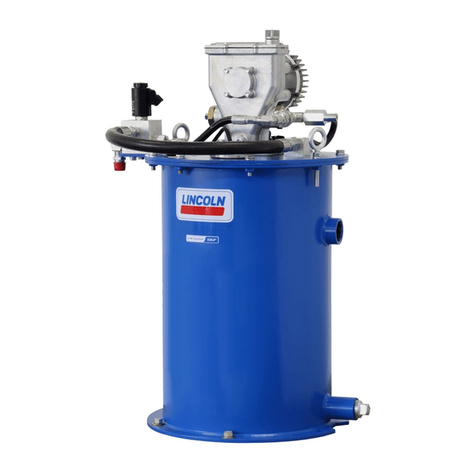
CENTRO-MATIC® PUMP, MODELS 84944 & 85461
4.1A-68530-A98
Form 402829
OPTIONALDEVICES
Low Level Kit
Model 249608 Low Level Kit can be installed whenever
higher viscosity greases or lower temperatures are
encountered and when an external indicator of lubricant
level is desired. The kit is composed of a follower with
wiper attached to a level indicator gage located on the
cover of the reservoir.
PUTTINGPUMPINTOOPERATION
Filling Reservoir
To bulk fill the reservoir, remove the lower and upper pipe
plugs from the side of the reservoir. Attach the appropriate
bulk-filling pump to the lower inlet (3/4 NPT). Fill reservoir
until grease appears at the top 1/2 NPT high level port.
Remove the bulk-filling pump. Replace both pipe plugs.
To fill the reservoir using a five-gallon pail of lubricant, first
remove the six bolts that secure the lid. Remove the entire
assembly of lid, pump and vent valve. Using pipe wrench
or vice grips, remove the filler nipple extension attached
inside the reservoir at the 3/4 NPT inlet nipple. Insert
opened pail of lubricant and reattach lid and pump
assembly.
Note: If pail lubrication is to be used, then the optional wing
screws (60) should be used in place of the hex bolt (35).
When filling the reservoir, caution should be used as
extreme pressure can cause damage to the reservoir or
serious personal injury.
MAINTENANCE&REPAIR
General Maintenance
Good housekeeping will go a long way in keeping a
lubrication system running without problems for many
years of use.
Keep area around pump clean. Clean off filling area prior
to filling reservoir. Clean area around filler after filling as
lubricants will attract dirt.
Keep lubricants clean and free of dirt and debris.
When replacing grease pails be especially careful to
prevent any foreign matter from entering the grease pail or
contaminating the grease, as it adheres to the pump.
In Case of Trouble
(See Trouble Shooting Chart Page 7)
Use the Trouble Shooting Chart to determine where to
look if problems occur.
See the sections below for replacement and repair of
specific areas of the check valve, vent valve or safety
unloader valve.
Each part is identified with a number keyed to the
matching part on the illustrated views.
General recommendations of tools required are also
specified in each step.
Pay particular attention to the Warning statements to
prevent personal injury and possible damage to pump
components.
Outlet Check Service (See Illustration Page 5)
1. Turn off and disconnect the hydraulic supply to the pump
assembly.
2. Standard tools required are a bench mounted vice, a set of
open end wrenches ranging from 7/16 to 1-1/2, a large 24
adjustable wrench and a smaller 10 adjustable wrench.
3. Remove bolts and lockwashers (44 & 45).
4. Loosen union (12) and set vent valve assembly to the side.
5. Remove entire outlet check assembly (6) by loosening
adapter (8) from pump outlet.
6. Remove adapter (8) from bushing (20).
7. Remove outlet connector (11) from bushing (20).
8. Remove ball check seat (21) from outlet connector (24).
9. Inspect all check components (19, 20, 21, 23) for presence
of foreign material, scoring and or other damage, which
may cause internal leakage.
10. If foreign material is present, clean components and
reassemble, making sure to replace gaskets (18 & 22).
Reverse the above procedure to reassemble. Torque
check assembly to 100 ft.-lbs.
11. If check components appear to be scored or damaged
replace all components (19, 20, 21, 23) and gaskets (18
& 22) with new ones. Reverse the above procedure to
reassemble. Torque check assembly to 100 ft.-lbs.
Vent Valve Service (See Illustration Page 5)
1. Turn off and disconnect the hydraulic supply to the pump
assembly.
2. Standard tools required are a bench mounted vice, a set of
open end wrenches ranging from 7/16 to 1-1/2, a large 24
adjustable wrench and a smaller 10 adjustable wrench.
3. Remove delivery hose (15). Remove vent hoses (42 & 46).
4. Remove bolts and lockwashers (44 & 45).
5. Loosen union (12) and remove vent valve.
6. Hold base of vent valve in vice to remove nipple (11) and
elbow (13). Turn vent valve in vice so that vice jaws are
gripping flats machined on base of vent valve.
7. Remove cylinder (25). Remove piston and packing
assembly (26) from cylinder. If leakage was evident from
side of cylinder then replace packing.
8. Remove packing assembly (28). If grease leakage was
evident from side of cylinder, then replace packing
assembly.
9. Inspect needle (27) and valve seat (29). If foreign matter is
lodged and is keeping the needle from sealing in valve
seat, clean and inspect for damage. If seat appears
damaged by nicks, grooves or scouring it should be
replaced. Remove valve seat (29) from valve body (31) by
placing a 3/4 open end wrench onto the flats and
loosening the seat. The use of an adjustable wrench over


