Page Number - 3
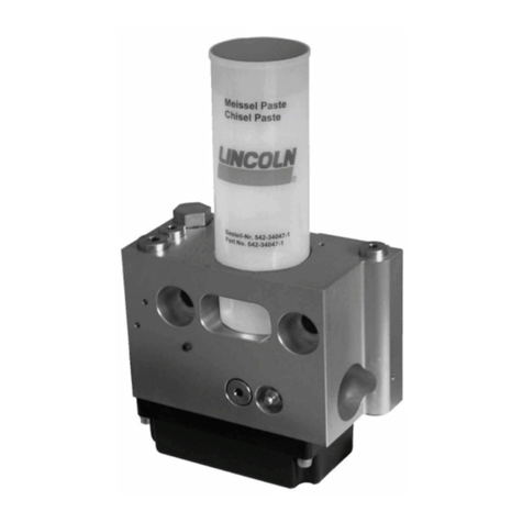
MODEL 4475 & 4480
1:1 AIR OPERATED PUMP
Form 422824
FAILURE TO HEED THE FOLLOWING WARNINGS INCLUDING MISUSE, OVER PRESSURIZING, MODIFYING PARTS, USING
INCOMPATIBLE CHEMICALS AND FLUIDS, OR USING WORN OR DAMAGED PARTS, MAY RESULT IN EQUIPMENT DAM-
AGE AND/OR SERIOUS PERSONAL INJURY, FIRE, EXPLOSION, OR PROPERTY DAMAGE.
Do not exceed the stated maximum working pressure of the pump or of the lowest rated component in your system.
Do not alter or modify any part of this equipment.
Do not operate this equipment with combustible gas or fuel, gasoline, diesel fuel, kerosene, etc.
Do not attempt to repair or disassemble the equipment while the system is pressurized.
Make sure all fluid connections are securely tightened before using this equipment.
Always read and follow the fluid manufacturers recommendations regarding fluid compatibility, and the use of
protecti e clothing and equipment.
Check all equipment regularly and repair or replace worn or damaged parts immediately.
Ne er point the dispensing al e at any part of the body or at another person.
Ne er try to stop or deflect material from dispensing al e or leading connection or component with your hand or body.
Always check equipment for proper operation before each use, making sure safety de ices are in place and operating
properly.
Always follow the pressure relief procedure after shutting off the pump, when checking or ser icing any part of the
system, and when installing, cleaning or changing any part of the system.
Annual inspection by a factory authorized ser ice center is
recommended.
INSTALLATION
Typical bulk tank and drum system hookups are shown and
described as follows only as a guide in selecting and
installing a system. Contact a Lincoln factory representati e
for assistance in designing a system for a specific require-
ment.
Lincoln recommends using Mini-regulator 602003 (1/4 port
size) with Gage 247843 and 1/4 I.D. Air line supply. See
Figure 3.
SPIGOT APPLICATIONS
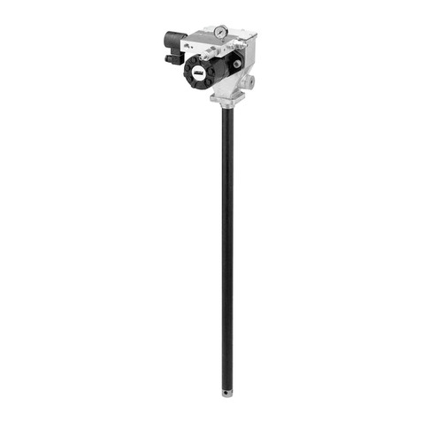
Make sure all connections are tight. Thread the pump tube
into the 3/4 NPT material inlet of the pump as shown in
Figure 1.
Loosen the bung collet and install the bung bushing into the
2 NPT fitting of your drum or tank. Slide the pump and
pump tube into the bung collet and adjust to desired height.
Make sure all connections are securely tightened.
To start pump in spigot applications, turn on the main air
supply. Slowly open the air regulator. Regulate air pressure
from 20-40 psig. Open the dispensing al e 1/4 turn to allow
air to be purged from the system. Allow pump to cycle until
fluid without air pockets flows from dispensing al e, then
close dispensing al e.
In a direct supply system, with adequate air pressure
supplied to the motor, the pump starts when the 1/4 turn
dispensing al e is opened and stalls against pressure
when it is closed.
The pump was tested in lightweight oil which was left in
to protect the pump from corrosion. Flushing the pump
before connecting it to the system might be desired to
pre ent possible contamination of the fluid you are
pumping.
Clean/flush the supply lines, hoses, reducers, connectors
and accessories with mineral spirits or oil based sol ent to
purge any contaminants such as dirt, moisture, or metal
sha ings that could damage the pump or system
components. Blow dry with air.
To reduce the risk of injury from splashing or static
sparking when flushing the pump with sol ents, always
hold a metal part of the dis-pensing al e firmly to the
side of a grounded metal pail and operate at lowest
possible fluid pressure.
