PREPARATION
WARNING! – Remove power to the system before assembling or disassembling the
system. A Charging Bay should not be added or removed with power applied to the
system.
ASSEMBLY
STEP 1: Turn the Master controller over so its boom is facing up. Push the two locking
ngers of the End Cap away from the Master Controller while also applying a slight
downward pressure to these ngers unl the End Cap disengages and slides parally
o the Master Controller. Slide the End Cap o and set aside.
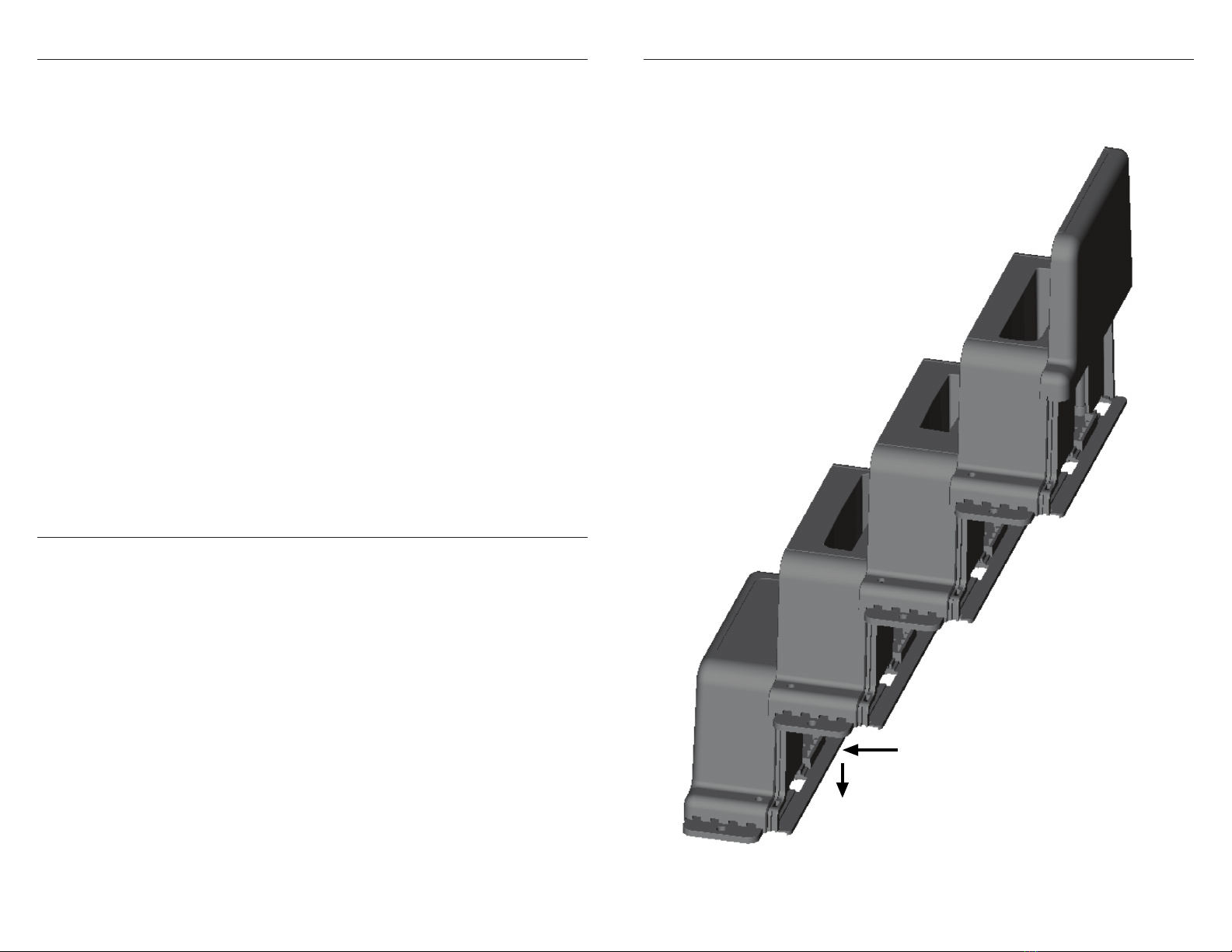
STEP 2: Turn the Master Controller right side up. Take a Charging Bay module and align
it so it is along side the Master Controller module (about 2” higher than the Master
Controller). While pushing the Charging Bay module against the Master Controller slide
it down so their interlocking grooves engage each other. Slide the Charging Bay module
down unl it is fully seated – the locking ngers of the Charging Bay module should
lock onto the boom of the Master Controller.
STEP 3: If another Charging Bay is to be added, align it along the assembled secon and
slide it down while pushing it together to engage the interlocking grooves. Connue to
slide it down unl fully seated.
STEP 4: Connue step 3 unl up to 16 Charging Bays have been connected to the
Master Controller.
STEP 5: Take the end cap from step 1, align it with the last Charging Bay and slide it
down to fully seat it.
STEP 6: Mount system where it will be used.
NOTE: The Baery Charging System is to be mounted on a at horizontal surface. It
may be mounted at an angle with the back of its base angled up to 30° above the
horizontal. In this case the unit must be secured to the mounng surface.
STEP 7: Slide the door on the side of the Master Controller to expose either the 4.5mm
jack or the 7.4mm jack that matches the Dell AC power adapter being used and plug
the cord into the Master Controller.
STEP 8: Apply power to the Dell AC adapter. Once the Master Controller recognizes
the AC adapter it will turn on its green indicator. Then as the Master Controller
communicates with each Charging Bay for the rst me that bay’s indicator will ash
green for 1 second. The system is now ready for use.
– Four quick amber blinks followed by 4 quick green blinks = Temporary baery fault.
Charging stopped if started. May resume if fault goes away. If fault persists for more
than 30 seconds fault indicaon changes to baery failure indicated above. Note: this
indicaon may be seen when a baery is rst inserted into a bay if the baery circuitry
has entered a sleep mode.
– Two quick amber ashes followed by two quick green ashes = Unsupported baery, no
charging allowed
– Blinking red = Baery temperature is colder than 32°F(0°C) or hoer than 122°F(50°C).
Charging of baery is stopped. Resumes when back in normal temperature range.
BATTERY CHARGING
Each baery charging bay will use up to 20W of power while charging its baery. The size
of the Dell power adapter will determine how many bays may charge at the same me.
See the list below for the number of baeries that can charge simultaneously when using
various Dell adapters to power the system.
45W adapter = 2 baeries simultaneously
65W adapter = 3 baeries simultaneously
90W adapter = 4 baeries simultaneously
130W adapter = 6 baeries simultaneously
180W adapter = 8 baeries simultaneously
240W or larger adapter = 9 baeries simultaneously
If more bays are connected than the number listed above the addional bays will wait unl
the previous baeries are fully charged to start their baery charging. No more baeries
than those listed above will ever charge at the same me. If a baery is removed and a
discharged baery is inserted into a bay, that bay will move to the end of the charging
sequence queue.
The average charging me to charge a fully discharged baery is:
– 3.75 Hrs for a Dell rugged 5420/5424/7424 baery
– 3 Hrs for a Dell rugged 7212 baery
Both baery type bays can be used in the same system.
With the charging mes listed up to twice the number of baeries can be fully
charged in an eight hour period by:
As baeries become fully charged swapping them out with discharged baeries or
having extra bays aached to the system (up to 16 bays total) that will charge their
baeries as previous baeries become fully charged.