No.39639 © LINDY ELECTRONICS LIMITED & LINDY-ELEKTRONIK GMBH - FIRST EDITION (APR 2010)
4
FOR COMMERCIAL USE ONLY! Tested to comply with FCC Standards
Shielded cables must be used with this equipment to maintain compliance with radio frequency energy emission regulations and ensure a
suitably high level of immunity to electromagnetic disturbances.
FCC Warning
This equipment has been tested and found to comply with the limits for a Class A digital device, pursuant to part 15 of the FCC Rules. These
limits are designed to provide reasonable protection against harmful interference when the equipment is operated in a commercial environment.
This equipment generates, uses, and can radiate radio frequency energy and, if not installed and used in accordance with the instruction manual,
may cause harmful interference to radio communications. Operation of this equipment in a residential area is likely to cause harmful interference
in which case the user will be required to correct the interference at their own expense.
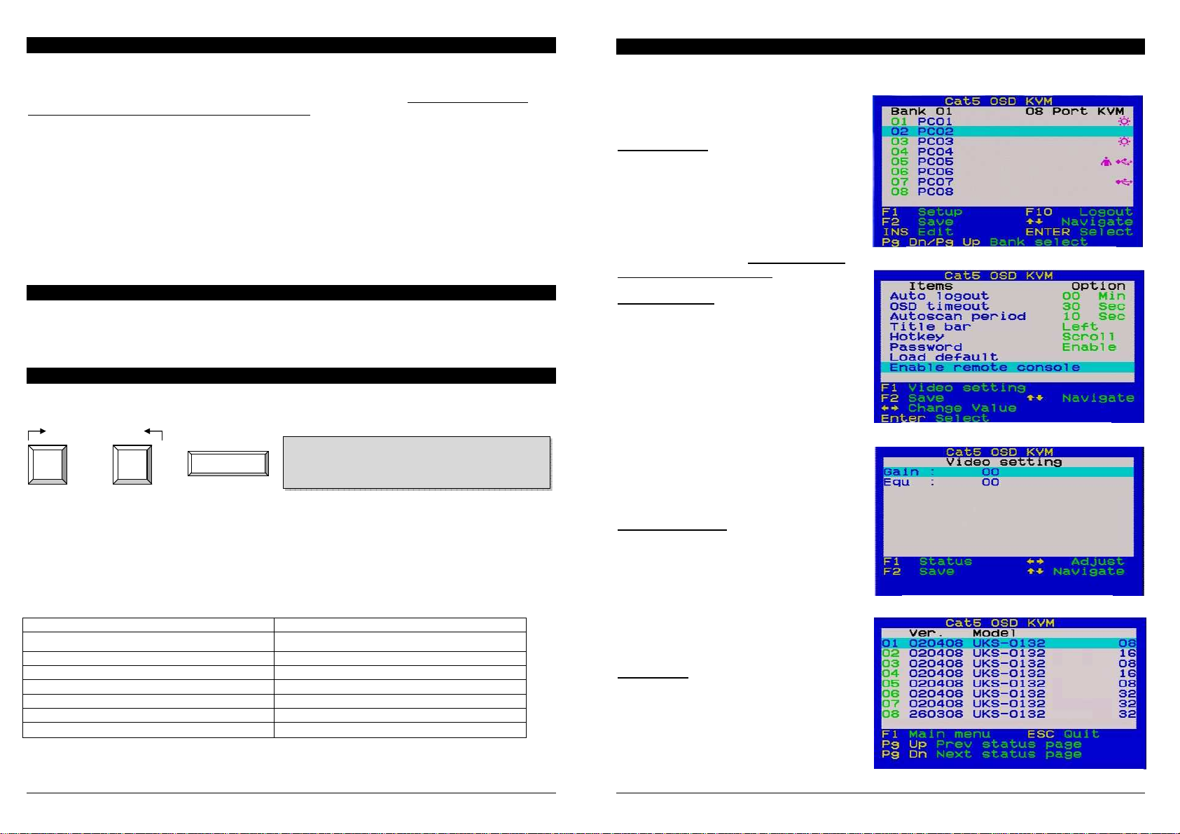
Computer Module Status Submenu
OSD Configuration Menu (Continued)
Computer Module Status Submenu
Use this page to check the firmware version of the
Cat.5/6 Computer Modules attached to a selected
KVM Switch (i.e. 120208 shown here is the FW
version of the KVM Switch), and perform manual
FW upgrades.
To do a manual FW upgrade of individual Cat.5/6
computer modules, just select the module to be
upgraded and press Enter to confirm the
automatic upgrade. During the upgrade process a
download bar will appear indicating the progress
of the upgrade.
In addition you can alternatively press F4 to toggle
between manual and auto (for all Cat.5/6 modules connected to this KVM Switch) upgrade mode. More
detailed information is provided with the Firmware upgrade files.
Troubleshooting
Before calling technical support, please try the following steps for easy troubleshooting.
Q1. My keyboard and/or mouse are locked up. What can I do for troubleshooting without rebooting
the computer and/or KVM?
A1. First, unplug the computer modules PS/2 or USB connections from the computer for few seconds and
plug it in again – alternatively plug the USB connector into to a different USB port. If it is PS2, always connect
the mouse connection first, then the keyboard connection. This should bring back the computer module if
only re-initialization is required. If any of the above does not help then you may have to reboot the computer
for a complete reset of the computer keyboard and mouse.
Q2. My monitor stays dark.
A2. Please check if the computer you want to access is in standby or power save mode with the monitor
switched off. If so please wake up the computer in the usual way.
The contact information for the LINDY technical support teams can be found on the LINDY website for each
country.
KVM Switch CAT-16 IP
No.39639 © LINDY ELECTRONICS LIMITED & LINDY-ELEKTRONIK GMBH - FIRST EDITION (APR 2010)
1
Introduction
The KVM Switch CAT-16 IP is designed to be installed into the back of the LCD Terminal Premium Secure to
provide a combined LCD Terminal KVM Switch in a 19” rack mounted 1U enclosure.
The KVM Switch CAT-16 provides 16 Cat.5/6 KVM server ports supporting both PS/2 and USB keyboard and
mouse connections. The KVM switch incorporates a modular concept design which allows for dual console
access for a Local & Remote user. The local console port allows direct access to the server rack, whilst the
second console option permits KVM over IP access allowing system administrators to access and administer
their servers from a remote office workstation over your LAN or via the internet. The optional KVM over IP
module may be purchased separately and is simply installed into the back of the KVM Switch CAT-16.
The KVM Switch CAT-16 is compatible with most computers that use standard VGA, PS/2 or USB mouse
and keyboards. Server connectivity is provided via the Cat.5/6 computer modules. Up to 7 further KVM
Switch CAT-32 (No.39632/39631) can be cascaded via daisy chain ports. Should you wish to mix other KVM
models or other brand KVMs then it has to be done via port cascading. In this case the other KVM hotkeys
have to be different from the default CAT-16 hotkey (configurable, default hotkey is Scroll Lock).
The KVM Switch CAT-16 has a single user password protection with auto logout security. The security
features for the KVM over IP user are based on SSL and additionally KVM encrypted connections with a
further level of password login. Details can be found in the manual for the KVM over IP Module.
Package Contents
Installation, Cable Requirements & Remote Access KVM over IP Module
The optional remote access KVM over IP module, LINDY No. 39636, can be installed at any time. To install it
into the KVM Switch CAT-16 ensure that the power supply is unplugged. Open the slot on the rear of the
KVM Switch and slide the module into the slot. Fix it with the original screw and store the spare bezel in a
secure place.
To connect each individual computer to the switch, Cat.5/6 computer modules are required. For USB or PS/2
computers different modules have to be used as listed below. A Cat.5e or 6 UTP cable of appropriate length
(max. 100m) is required to connect the KVM Switch to the computer modules
For PS/2 computers: Cat.5/6 Computer module PS/2 & VGA, No. 39633
For USB computers: Cat.5/6 Computer module USB & VGA, No. 39634
To assemble the KVM Switch CAT-16 in the back of the LCD Terminal,install the two
brackets to the KVM Switch using the supplied screws. Then attach the KVM Switch
on the back of the LCD Terminal so that the 3 connectors (IEC, HD15M and HD15 F)
fit properly. Tighten the 4 thumb screws properly.
Daisy Chaining several KVM Switches
The KVM Switch CAT-16 can be daisy chained with up to 7 KVM Switch CAT-32 models providing an
additional 32 computer ports each, 240 computers in total. The Daisy Chain OUT port of the KVM Switch
CAT-16 has to be connected to the Daisy Chain IN port of the next slave KVM switch CAT-32 using the
Daisy Chain Cable supplied with the CAT-32. Longer cables are available from LINDY, No. 39637 (1m),
39638 (2m). When all KVMs have been installed connect the power supplies to each KVM Switch and power
up the KVM switches in sequence starting from the master KVM.
KVM Switch CAT-16 IP
LCD Terminal installation kit
Firmware upgrade Cable
User manuals in different languages
you how to quickly set up the device for use. For the features and detailed operating
instructions of the KVM over IP module please refer to the manual enclosed with the
KVM over IP module (No. 39636).