LineEye SI-60 User manual

Interface Converter
Instruction Manual
34th
The CD-ROM attached to a product contains the newest English and Japanese
instruction manuals in a PDF format. Please also refer to them.
LAN RS-232C
SI-60 / SI-60F / SI-60F-L
LAN RS-232C x2
SI-60X
LAN(PoE) RS-232C
SI-60P / SI-60FP

1
Notice
Under the copyright laws, it is prohibited to reprint or duplicate any part or the whole of
this instruction manual without priority from LINEEYE CO., LTD. ("LINEEYE")
All company and product names in this manual are trademarks or registered trademarks of
their respective companies.
The contents of this manual and specications of the products are subject to change
without notice.
This manual has been designed and edited with great care to give you all information. If
you have any questions, feel free to direct your inquiries to LINEEYE.
LINEEYE makes no warranty or guarantee, either expressed or implied with respect to its
quality, performance, merchantability, or tness for a particular purpose. LINEEYE shall
not be liable for direct, in-direct, special, incidental, or consequential damages resulting
from any defect in the product. The warranty and remedies set forth above are exclusive
and in lieu of all others.
Thank you for your purchase of SI series. To use it correctly,
you are advised to read and understand this instruction manual
thoroughly. Keep this together with the warranty.
Introduction
Copyright ©2010-2021 LINEEYE CO., LTD. All rights reserved.

2
LINEEYE has developed and manufactured this product for purpose of using with
electrical devices such as a computer, a personal device, a measurement device,
semiconductor manufacturing equipment, a vending machine, a sequencer, display
equipment and so on. LINEEYE does not manufacture this product under the
purpose of using with equipment which may cause malfunction to do harm to the
human body: control equipment for nuclear, aircraft equipment, life maintenance
equipment, traffic signals, etc. Therefore, LINEEYE makes no guarantee with
the mentioned-above use. If you use this product for the purposes mentioned
above, please contact LINEEYE considering safety like Fail Safe under your
responsibilities.
Do not disassemble or modify the converter and AC adapter.
This may cause overheating, a re, an electric shock, injury or unit malfunction.
Stop using the converter immediately when smoke, smells, or unusual sound emanates
from itself.
Continuous use may cause a burn, re, or electric shock.
Keep the products dry. Keep them away from water.
Failure to do so may cause overheating, an electric shock, or unit malfunction.
Do not insert the metal scrap or the rubbish such as lead wires into the opening.
Doing so may cause overheating, an electric shock, or unit malfunction.
Never touch the converter and AC adapter with wet hands.
Doing so may cause an electric shock.
Remove the dust on the AC adapter periodically to prevent the heat and ignition.
*"Injury" indicates injury, burn, an electric shock, or the like which does not
require hospitalization or the extended hospital visit. "Material damage" indicates
damage related to a house, a building, furniture, apparatus, livestock or a pet.
Danger Level
Be sure to read the following
Safety Information
Should the device be used without following these symbols, there
is a possibility of accidents, such as a death or a serious injury,
occurring.
Should the device be used without following these symbols, there
is a possibility of accidents, such as an injury and material damage,
occurring.

3
Do not install the converter in the unstable or vibrating place.
Doing so may cause unit malfunction or injury.
Do not install the converter in any temperature and humid places, or any places which has
the extreme temperature change.
Doing so may cause unit malfunction.
Do not install the converter in any places exposed to direct sunlight.
Doing so may cause a burn or unit malfunction by overheating.
Be sure not to short-circuit the pins on the connector.
Doing so may cause unit malfunction or injury.
Use the included AC adapter with the converter only.
Failure to do so may cause re or injury by overheating.
Be sure to hold the converter when you disconnect the AC adapter from it.
Failure to do so may cause re or an electric shock by damaging a cord.
Please do not damage the power cable by pulling, stamping, or tearing.
This may result in a injury, an electric shock, re, explosion and or a breakdown due to
overheating.
Do not place the cord of the AC adapter near heating equipment.
Doing so may cause re or an electric shock by melting the cord's cover.
Never use the converter in the place where an inammable gas leaks.
Doing so may cause ignition.
Do not conduct the installation or wiring work when power is applied.
Doing so may cause an electric shock or unit malfunction.
Do not use the damaged cables.
Doing so may cause re by overheating.
Use the included AC adapter or ones specied by LINEEYE.
Failure to do so may cause overheating, re, an electric shock, or injury.
Never touch the converters and cables while thunderbolts are occurring.
Do not connect the power cord to an outlet that has an illegal number of connections.
Doing so may cause re by overheating.

4
■■ Contents ■■
Chapter 1 Before Using The Product 5
1-1. Unpacking and Product
Composition....5
1-2. How to read
this instruction manual ...5
1-3. Overview ....................................6
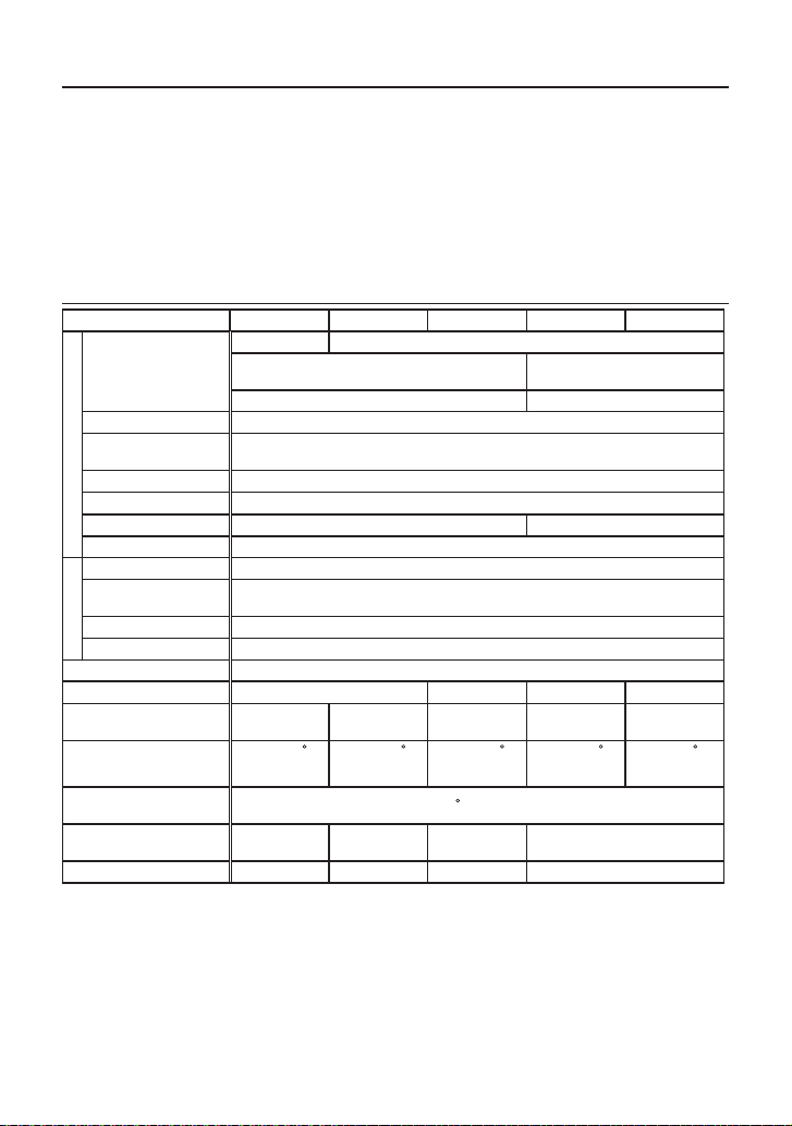
1-4. Specications .............................6
Chapter 2 SI-60F Usage.................... 7
2-1. SI-60F Overview and Features ..7
2-2. SI-60F Panel Explanation ..........8
2-3. SI-60F Cable Connection...........9
2-4. SI-60F Power Source .................9
Chapter 3 SI-60 Usage.................... 10
3-1. SI-60 Overview and Features ..10
3-2. SI-60 Panel Explanation .......... 11
3-3. SI-60 Cable Connection...........12
3-4. SI-60 Power Source .................12
Chapter 4 SI-60X Usage ................. 13
4-1. SI-60X Overview and Features13
4-2. SI-60X Panel Explanation .......14
4-3. SI-60X Cable Connection........15
4-4. SI-60X Power Source ..............15
Chapter 5 Basic Conguration........ 16
5-1. Connect to the LAN network...16
5-2. Basic conguration ..................16
5-3. Default IP address ....................17
5-4. Usage of DeviceInstaller..........17
5-5. Conrm IP address...................18
5-6. Assign IP address .....................19
Chapter 6 Conguration Using
Web Manager . 20
6-1. Web Manager Usage ................20
6-2. Communication conditions of
serial port .........................................22
6-3.Set up LAN connection mode...22
6-4. Other Setting ............................23
Chapter 7 Setup Example................ 24
7-1. Server mode usage ..................24
7-2. Client Mode Usage ..................25
7-3. Using two units of converter....26
Chapter 8 COM Port Redirector ..... 28
8-1. About Virtual COM Port .........28
8-2. Basic Setting.............................28
8-3. Install COM Port Redirector....28
8-4. COM Port Redirector...............29
Chapter 9 Documents...................... 30
9-1. Factory setting..........................30
9-2. How to apply the factory setting31
9-3. General-purpose I/O pins.........34
9-4. LAN Connector Specication 34
9-5. Installation Method ..................35
9-6. Ordering information ...............37
9-7. Option.......................................37
Chapter 10 Warranty and
After-Sales Service... 38
10-1. Troubleshooting .....................38
10-2. Warranty and Repair ..............40
10-3. After-Sales Service.................40

5
Chapter 1 Before Using The Product
1-1. Unpacking and Product Composition
Make sure of the following when unpacking the product.
Please let your LINEEYE distributor or LINEEYE know if you nd any damage to
the product caused by transportation, or if there are accessories lacking.
SI-60, SI-60F, SI-60F-L, SI-60X
Converter : 1
AC Adapter : 1*1 *3
Utility CD-ROM : 1*2 *3
Instruction Manual : 1*3
Warranty : 1
SI-60P, SI-60FP
Converter : 1
Utility CD-ROM : 1*2
Instruction Manual : 1
Warranty : 1
*1 For the foreign market (not Japan), the model (with -E) includes an AC adapter of
AC100V-240V (6A181WP09). For Japanese market the model (without -E) includes
an AC adapter of AC100V (VFN-650B)..
*2 This CD-ROM includes manuals and tools for setup. Please read the README.txt for
further details.
*3 -NS models do not have these items.
1-2. How to read this instruction manual
First, please read instruction about power supply and how to connect the device at the chapter of the
model. Then read chapter 5, chapter 6, and chapter 8 for the details of the conguration and IP address
setting.
Description of I/O pins on the XPort
The description of I/O pins of XPort at conguration diers depending on the version of the WEB manager.
And the version of the WEB manager also diers depending on the version of the XPort. Please refer to the
following information to apprehend the meaning of the description at conguration.
Web Manager Ver1.8.0.1 or before : CP0, CP1, CP2
Web Manager Ver1.9.0.1 or later : CP1, CP2, CP3. (Examples in this manual use this
description)
SI-60F-L
SI-60F-L is the model which has a dierent type of body but has same function as that of SI-60F. When you need
information about SI-60F, please see the reference about SI-60F. Please note that SI-60F-L is for wall mounting, thus
optional L Bracket and DIN plate cannot be used for SI-60F-L.
SI-60FP and SI-60P
SI-60FP and SI-60P are the model which has the same function as that of SI-60F and SI-60 and also support PoE (Power
over Ethernet: IEEE 802.3af/at) power supply. When you need information about SI-60FP or SI-60P, please see the
reference about SI-60F and SI-60 because the functions other than PoE are the same as those of SI-60F and SI-60.

6
1-3. Overview
SI-60F/SI-60X/SI-60 are communication converters to convert asynchronous
communication of serial interface to TCP/IP communications on Ethernet LAN. SI-60/
SI-60F convert one port of RS-232C and SI-60X converts two ports of RS-232C. These
converters have built-in Lantronix XPort at the LAN interface part. You can control
the device which has a serial port from a PC on the network by socket communication.
By using COM port redirector, which is included in the CD-ROM, you can use it like
com port communication. It is also possible to extend the serial line without PC by
connecting the two devices by LAN.
1-4. Specications
SI-60X SI-60FP SI-60F/(-L) SI-60P SI-60
S
e
r
i
a
l
Interface
RS-232C x2 RS-232C
Dsub9 Pin (Male)
#4-40 UNC (inch screw)
Dsub25 Pin (Female)
M2.6 mm Screw
DTE xed DTE/DCE Switchable
Synchronous Method Asynchronous
Baud Rate (bps) 300/600/1200/2400/4800/9600/19200/38400/57600/115200/230400/
460800 *1/921600 *1
Data Frame Structure
Data (7 or 8) + Parity (Even, Odd or None) + Stop (1 or 2)
Flow Control Xon/o RTS/CTS
LED Display SD,RD SD,RD,RS,CS,(6-20)
Surge Protection 15KV ESD
L
A
N
Interface Ethernet IEEE802.3 RJ-45 connector 10BASE-T/100BASE-TX
Protocol ARP, TCP/IP,UDP/IP, ICMP, SNMP, TFTP, Telnet, DHCP, BOOTP, HTTP,
AutoIP
LED Display 10BASE-T*2,100BASE-TX,*2 Activity, Link, Full/Half duplex*2
Transformer Insulation 1500V
Management Web manager, Telnet connection, Serial port connection
Power Supply DC5 to 30V DC5 to 25V DC5 to 30V DC5 to 12V
Power Consumption 1.5W / 2.8VA*3 1.5W(DC-IN)
2W(PoE) 1.5W / 2.8VA*3 1.5W(DC-IN)
2W(PoE) 3W / 4.2VA*3
Operating
Temperature,Humidity
-10 to +50 C,
10 to 95%RH
-20 to +50 C,
10 to 95%RH
-10 to +50 C,
10 to 95%RH
-20 to +50 C,
10 to 95%RH
-10 to +50 C*4,
10 to 95%RH
Storage
Temperature,Humidity -20 to +80 C, 10 to 95%RH
External Dimension
(W x D x H)
78×85×
24mm
58×88×
24mm
82×88×
24mm*5 65×95×24mm
Weight 220g 170g 170g 200g
*1 SI-60 cannot be used at 460.8Kbps and 921.6Kbps.
*2 On SI-60F and SI-60, you can distinguish 10BASE-R or 100BASE-TX and Half-duplex or Full-
duplex by seeing the lighting color of the LED.
*3 Act as a Class 1 receive device of Power over Ethernet: IEEE802.3af/at
*4 In the case of using the attached AC adapter (AC100V).
*5 When the power supply voltage, which is supplied from the connector (SI-60), is DC10V or
higher the operating temperature is limited up to +40 degree.
*6 Includes the mount part.

7
Chapter 2 SI-60F Usage
2-1. SI-60F Overview and Features
SI-60F converts asynchronous communications of RS-232C interface to TCP/IP or
UDP/IP communications on Ethernet LAN. Having XPort as its LAN interface, SI-
60F oers highly-reliable communication.
*For further detail about conguration and IP address setting, please refer to chapter 5, 6, and 8.
SI-60F/SI-60FP
*The appearance of SI-60FP diers at model name and description on the LAN connector.
SI-60F-L (Wall hanging model)
The functions of SI-60F and SI-60F-L are the same. For the detailed dimensions
of SI-60F-L, please refer to “To attach to the wall (SI-60F-L)” of 9-6. Installation
Method.

8
2-2. SI-60F Panel Explanation
No. Name Explanation Note
1 Power LED It lights when the SI-60F is powered.
2 Data Status LED
It lights when SD/RD signal of RS-232C is active.
The numbers in the parentheses indicate the pins of
RS-232C.
3AC Adapter Jack A socket to connect to an AC adapter. [ 2-4. ]
4 Ethernet Connector Ethernet IEEE802.3 RJ-45 connector
10Base-T/100Base-TX auto-detection available. [ 9-4.]
5RS-232C
Connector Dsub9 pin (male) Screw: #4-40 UNC(inch screw)
6 Rubber foot Rubber foot to place SI-60F horizontally [ 9-5.]
7 MAC address seal The hardware address (MAC address) of the unit.
RS-232C Connector Pin Assignment
Pin
No. Name I/O
Direction *1 Description
1 CD - non-connected
2 RD In Reception Data
3 SD Out Transmission Data
4 ER In Internal connection to 6 pin *2
5 GND - Signal Grand
6 DR In Internal connection to 4 pin *2
7 RS Out Transmission Request
8 CS In Transmission Permit
9 CI - non-connected
*1
"Out" means a direction to output signals from the converter.
"In" means a direction to input signals to the converter.
*2 Inputs the negated signals to the CP1 terminal on a built-in XPort.
SD (3)
RD (2)
RS (7)
CS (
8)
DR (6)
ER (4)
GND (5)
LAN Device
Data OUT(TXD)
Data IN(RXD)
CP1(RTS)
CP2
CP3(CTS)
RS-232C
The LAN device for SI-60F is XPort and the one for SI-60FP is xPico.
* Descriptions in () is for SI-60FP
* The numbers in () on RS-232C side are the pin numbers of DSUB connector.

9
2-3. SI-60F Cable Connection
LAN
Connect to the LAN connector of SI-60F with a LAN cable of category 5e or more.
[ 5-1.Connect to the LAN network]
RS-232C
Connect by the proper RS-232C cable which ts the shape of the RS-232C connector
on the target devices. Then, make sure of the input/output specication of signal pins.
e.g.1: Connecting the serial port (Dsub9 pin - male) of SI-60F to the device (Dsub25
pin, female) of DCE specication.
Use straight connection cable such as SI-RS259(SI-RS259 cable is an
optional cable.) to connect.
e.g.2: Connecting the serial port (Dsub9 pin - male) of SI-60F to the device
(DSUB9pin, male) of DTE specication.(male)
Use cross connection cable which both ends with DSUB9pin(female) to
connect.
e.g.3: Connecting the AUX port (Mini DIN8 pin, female) of analyzers, (LE-8200/35
00/2500/7200/3200/2200/1200) to SI-60F.
Use LE2-8V cable to connect.(LE2-8V cable is an optional cable.)
2-4. SI-60F Power Source
There are two ways to supply power to SI-60F.
Supply by AC
1. Connect the plug of the AC adapter to the DC jack of SI-60F.
2. Plug the AC adapter to an outlet to supply power.
Please use appropriate AC adapter which complies with the power specication and
safety standards of the country in which you use SI-60F.
Model Power specication Safety standards
VFN-650B AC 100V ± 15%, 50/60 Hz PSE
6A-181WP09 AC 90 - 264 V, 50/60 Hz PSE/UL/CUL/GS/CCC/CE
Supply by DC
1. Prepare external DC source of 5 - 25V*1, 1.5W*2 or more.
*1: SI-60FP supports up to 30V.
*2: The current consumption is as follows: 250mA (when DC is 5V), 100mA (when DC is
12V), 50mA (when DC is 25V)
2. Connect the DC-IN of SI-60F with the output terminal of the external source by
using SIH-2PG (an option sold separately). It does not matter + or – because the
DC-IN is non-polar.*3
*3: The size of the DC plug which ts in the DC-IN is as follows: Outer diameter is 5.5mm,
inner diameter is 2.1mm, length of top of the plug is 9.5mm.
When powered by a PoE supported hab (SI-60FP).
Power the unit by using LAN cable and a hub which supports PoE (IEEE 802.3af or
IEEE 802.3at). By the hub SI-60FP is regarded as a PD (Powered device) of Class 1 (0.44
– 3.84W).

10
Chapter 3 SI-60 Usage
3-1. SI-60 Overview and Features
SI-60 converts asynchronous communications of RS-232C interface to TCP/IP or
UDP/IP communications on Ethernet LAN. Having XPort as its LAN interface, SI-60
oers highly-reliable communication.
*For further detail about conguration and IP address setting, please refer to
chapter 5, 6, and 8.
SI-60 adopts DSUB25 pin connector and you can switch it to DTE or DTC, which
allows you to connect any device to RS-232C interface of SI-60.
The following chart shows the internal structure of SI-60.
When switched to DTE
SD (2)
RD (3)
RS (4)
CS (5)
DR (6)
ER (20)
GND (7)
SW : DTE
LAN Device
Data OUT(TXD)
Data IN(RXD)
CP1(RTS)
CP2
CP3(CTS)
RS-232C
When switched to DCE
SD (2)
RD (3)
RS (4)
CS (5)
DR (6)
ER (20)
GND (7)
SW : DTE
LAN Device
Data OUT(TXD)
Data IN(RXD)
CP1(RTS)
CP2
CP3(CTS)
RS-232C
The LAN device for SI-60 is XPort and the one for SI-60P is xPico.
* Descriptions in () is for SI-60P
* The numbers in () on RS-232C side are the pin numbers of DSUB connector.
[ 3-2. SI-60 Panel Explanation ]

11
3-2. SI-60 Panel Explanation
* The appearance of SI-60P diers at model name and description on the LAN connector.
No. Name Explanation Note
1
DTE/DCE Switch
Switcher to change the specication of RS-232C connector
of SI-60 to DTE or DCE. [ 3-1.]
2
Power LED
It lights when the SI-60 is powered.
3
Data Status LED
It lights when each signal of RS-232C is active.
The numbers in the parentheses indicate the pins of RS-232C.
4
AC Adapter Jack
A socket to connect to an AC adapter. (Non-polar) [ 3-4. ]
5
Ethernet Connector
Ethernet IEEE802.3 RJ-45 connector 10Base-T/100Base-TX
auto-detection available. [ 9-4.]
6
RS-232C Connector
Dsub25 pin (Female) M2.6 mm Screw
7 Rubber foot Rubber foot to place SI-60 horizontally
[ 9-5.]
8 MAC address seal The hardware address (MAC address) of the unit.
RS-232C Connector Pin Assignment
Pin No. *1 Name I/O Direction *2
Description
DTE DCE
1 FG - Frame Grand
2 SD Out In Transmission Data
3 RD In Out Reception Data
4 RS Out In Transmission Request
5 CS In Out Transmission Permit
6 DR In In Internal connection to 20 pin*3
7 GND - - Signal Grand
9 +DC IN - - External power supply input *4
20 ER In In Internal connection to 6 pin *3
*1 Pins not mentioned in this table indicate the non-connected terminals.
*2
"Out" means a direction to output signals from the converter.
"In" means a direction to input signals to the converter.
*3 Inputs the negated signals to the CP1 terminal on a built-in XPort.
*4
[ 3-4. SI-60
Power Source
]

12
3-3. SI-60 Cable Connection
LAN
Connect to the LAN connector of SI-60 with a LAN cable of category 5e or more.
[ 5-1. Connection to the Networok ]
RS-232C
Connect with the proper RS-232C cable which ts the shape of the RS-232C connector
on the target devices. Then, make sure of the input/output specication of signal pins and
connection of the RS-232C cable. Set DTE/DCE switch.
e.g.1: Use straight connection cable to connect the device which has DCE specications.
Set DTE/DCE switch to DTE.
e.g.2: Use SI-RS259 cable to connect the PC(DTE).
Set DTE/DCE switch to DCE.
e.g.3: Use LE2-8V cable to connect the AUX port (Mini DIN8 pin, female) of analyzers,
(LE-8200/3500/2500/7200/3200/2200/1200) to SI-60.
Set DTE/DCE switch to DTE.
3-4. SI-60 Power Source
There are two ways to supply power to SI-60.
Supply by AC
1. Connect the plug of the AC adapter to the DC jack (DC-IN) of SI-60.
2. Plug the AC adapter to an AC outlet to supply power.
Please use appropriate AC adapter which complies with the power specication and safety
standards of the country in which you use SI-60.
Model Power specication Safety standards
VFN-650B AC 100V ± 15%, 50/60 Hz PSE
6A-181WP09 AC 90 - 264 V, 50/60 Hz PSE/UL/CUL/GS/CCC/CE
* Power consumption when using an AC adapter “VFN-650B” is about 4.2VA (for SI-60).
Supply by RS-232C connector
1. Prepare DC source of 5 - 12V (DC 5 - 9V is recommended), 4W or more.Note:
Current consumption of SI-60 is up to 250mA regardless of supply voltage. External
source of lower voltage is recommended. Because the more voltage is, the more
power consumption and heat tend to be.
2. Process a RS-232C cable and connect the 9th pin of the RS-232C connector with
the plus pole of the external source and connect the 7th pin with the minus pole of
the source.
When powered by a PoE supported hab (SI-60P).
Power the unit by using LAN cable and a hub which supports PoE (IEEE 802.3af or
IEEE 802.3at). By the hub SI-60P is regarded as a PD (Powered device) of Class 1 (0.44
– 3.84W).

13
Chapter 4 SI-60X Usage
4-1. SI-60X Overview and Features
SI-60X converts two ports of asynchronous communications of RS-232C interface to TCP/
IP or UDP/IP communications on Ethernet LAN. Having WiPortNR as its LAN interface, SI-
60X oers access to two RS-232C ports through two local ports of IP addresses set on SI-
60X. SO-60X has a switch to initialize it to factory default setting (INTI SW), which helps
when you cannot nd out the IP address etc. SI-60X is suitable when two devices of RS-
232C interface are nearby and you need to convert the communication data of the devices
into LAN.
*For further detail about conguration and IP address setting, please refer to chapter 5, 6,
and 8.
The following chart shows the internal structure of SI-60X.
WiPortNR
TXD0
RXD0
RTS0
CTS0
CP3
CP4
TXD1
RXD1
RTS1
CTS1
CP5
CP6
CP9
SD (3)
RD (2)
RS (7)
CS (8)
ER (4)
DR (6)
GND (5)
INIT SW
RESETIN
Edge detecting
circuit
RJ-45
LAN
SD (3)
RD (2)
RS (7)
CS (8)
ER (4)
DR (6)
GND (5)
RS-232C (2)
RS-232C (1)

14
4-2. SI-60X Panel Explanation
No. Name Explanation Note
1 DC-IN 1 A socket to connect to an AC adapter. [ 4-4. ]
2 DC-IN 2 XH connector for DC supply (non-polar)Inside of SI-60X , DC-IN 2 is
connected in parallel with DC-IN 1. [ 4-4. ]
3 INIT SW A switch to initialize SI-60X
4 Ethernet Connector Ethernet IEEE802.3 RJ-45 connector 10Base-T/100Base-TX auto-
detection available. [ 9-4.]
5 LAN LED The LED on the left lights when linked.The LED on the right lights
when communicating.
6RS-232C (1)
Connector RS-232C Port 1 *2Dsub9 pin (male) Screw: #4-40 UNC (inch screw)
7. RS-232C (2)
Connector RS-232C Port 2 *2Dsub9 pin (male) Screw: #4-40 UNC (inch screw)
8. Data Status LED (1) It lights when SD/RD signal of RS-232C port 1 is active.
9. Data Status LED (2) It lights when SD/RD signal of RS-232C port 2 is active.
10. Power LED It lights when the SI-60X is powered.
11. Rubber foot Rubber foot to place SI-60X horizontally [ 9-5.]
12. MAC address seal The hardware address (MAC address) of the unit.
RS-232C Connector Pin Assignment
Pin No. Name I/O Direction *1 Description
1 CD - non-connected
2 RD In Reception Data
3 SD Out Transmission Data
4 ER In Internal connection to 6 pin *2
5 GND - Signal Grand
6 DR In Internal connection to 4 pin *2
7 RS Out Transmission Request
8 CS In Transmission Permit
9 CI - non-connected
*1.
“Out” means “from SI-60X” and “In” means “to SI-60X”.

15
4-3. SI-60X Cable Connection
LAN
Connect to the LAN connector of SI-60X with a LAN cable of category 5 or more.
[ 5-1. Connection to the Networok ]
RS-232C
SI-60X has two Dsub9 pin(male) of DTE specication.
Connect by a proper RS-232C cable which ts to the RS-232C connector of the target device.
Please make sure of the input/output specication of signal pins.
e.g.1: To connect the serial port (Dsub9 pin - male) of SI-60X with a device (Dsub25 pin,
female) of DCE specication, use straight connection cable such as SI-RS259. (SI-
RS259 cable is an optional cable.)
Set DTE/DCE switch to DTE.
e.g.2: To connect the serial port (Dsub9 pin - male) of SI-60X with a device (DSUB9pin,
male) of DTE specication, use cross connection cable which has ends of
DSUB9pin (female).
4-4. SI-60X Power Source
There are two ways to supply power to SI-60.
Supply by AC
1. Connect the plug of the AC adapter to the DC-IN1 jack of SI-60X.
2. Plug the AC adapter to an AC outlet to supply power.
Please use appropriate AC adapter which complies with the power specication and safety
standards of the country in which you use SI-60X.
Model Power specication Safety standards
VFN-650B AC 100V ± 15%, 50/60 Hz PSE
6A-181WP09 AC 90 - 264 V, 50/60 Hz PSE/UL/CUL/GS/CCC/CE
Power supply by branch cable
When you place two SI-60Xs nearby, you can supply
power to SI-60X with an AC adapter by using an
optional power branch cable (LAH-2XH). To do this,
please use 6A-181WP09 (AC adapter) because it has
ample output capacity.
AC Adapter
Converter1 Converter 2
Power branch cable
Supply by DC
1. Prepare external DC source of 5 - 30V, 1.5W or more.
*Current consumption of SI-60X is as follows: 250mA (when DC is 5V), 100mA (when
DC is 12V), 45mA (when DC is 30V)
2. Connect the DC-IN2 of SI-60X with the output terminal of the external source by using
optional power cable (such as LAH-15XH). It does not matter + or – because the DC-
IN2 is non-polar.
*A connector of the cable which ts in the DC-IN2 is as follows: XHP-2 (JST Mfg.
Co., Ltd.) and SXH-001T-P0.6 (crimp contact, JST Mfg. Co., Ltd.). Please use
appropriate crimp tools when you make a cable by yourself.

16
Chapter 5 Basic Conguration
5-1. Connect to the LAN network
Connect LAN connector of converter to the HAB/PC using LAN cable.
LAN Cable
HUB
LAN Cable(Cross Cable)
*This converter does not have AutoMDI/MDI-X function to nd the LAN port. To
connect LAN port of PC directly, use the LAN cable with cross connection.
* Try to use a short LAN cable when concerning the noise.
5-2. Basic conguration
Conguration can be set from following procedure.
Set through network using Web browser
Input the IP address in the Web browser of the PC, and set from the Web
manager.
Refer to "Chapter 6".
Use set-up mode
Connect the converter by serial/telnet connection, and then open the set-up mode.
(For serial connection, input the special command after turning on the power to enter into
the set-up mode. Use "RS-232C port 1" for SI-60X.)
Refer to [ XPort User Guide (XPort_UG.pdf) ] and [ WiPort NR User Guide
(WiPort-NR_UG.pdf) ] in the CD-ROM.
If entering the incorrect IP address, it may aect the whole network. To use it
properly, consult with your network manager. Please write down the important
conguration in case of resetting.
IP Address .....................[ . . . ]
Subnet Mask..................[ . . . ]
Default Gateway............[ . . . ]
Above information and passward are necessary to reset the device.
If loosing those, the device may need to be repaired.

17
5-3. Default IP address
As a factory setting, DHCP client mode and AutoIP function automatically set IP address.
* When the IP address is 0.0.0.0 (factory setting), those functions are valid. When IP
address is 0.0.1.0, only DHCP client function is valid.
When having DHCP server in the network
IP address is automatically set from the DHCP server when turning on the power
of device.
When not having DHCP server in the network
One of the IP addresses of "169.254.1.0" to "169.254.254.255" is automatically set by the
AutoIP function when turning on the power of device.
Refer to "Chapter 5.4"
5-4. Usage of DeviceInstaller
Install the DeviceInstaller of Lantronix for setting the IP address.
Preparation: Log to the PC as administrator. If you had already installed the previous
version of DeviceInstaller, uninstall it.
*If you would like to use the converter with XPort rmware Ver.1.8, used the previous
version of DeviceInstaller. The latest XPort rmware is displayed as "Unknown:x5"
or "Unknown:x9".
1 Double click on "setup_di_x86x64cd_4.4.0.4.exe" in the "/lantronix/DeviceInstaller/
ver4.4.x.x" folder. If you nd the latest version in the CD-ROM, use the latest
version.
2 Install it following the wizard.
* OS for DeviceInstaller(v4.4.x.x): Windows x86: 7, 8/8.1, 10
Windows x64: 7, 8/8.1, 10, Server 2008/2012
* If the PC is connected to the Internet,".NET Framework" is automatically installed.
Refer to the "Release.txt" le in the CD-ROM for information of ".NET Framework"
version.

18
3.Click [No] if following dialog is appeared.
5-5. Conrm IP address
1. Connect the converter to the network and turn on the power.
2. Open the DeviceInstaller from Start menu.
3. A device which has a LAN device of Lantronix is displayed on the main window
4. Select the one matched with the hardware (MAC) address and conrm the IP
address. Hardware (MAC) address is written on the backside of label of the
converter.

19
5-6. Assign IP address
1.Click on IP assignment.
2.Select the method and then click [Next].
* Consult with your network manager.
* Recommend not invaliding the [Auto-IP] function.
4. Click [Assign] to validate the conguration.
Do not turn off the power of converter until completing the restart after clicking
[Assign]. Writing the wrong conguration on the LAN device of Lantronix can cause
a malfunction.
*Refer to the online help of DeviceInstaller for appropriate use of DeviceInstaller.
Note
IP address can be set using the set-up mode.
Refer to[Xport User Guide (XPort_UG.pdf)] and [WiPort NR User Guide
(WiPort-NR_UG.pdf)] in the CD-ROM.
IP address can be set using the conguration tool "SILANIOinit".
Refer to [SILANIOinit.txt (instruction)] in the CD-ROM.
To valid the DHCP
client and AutoIP
address function.
To set xed IP
address.
3. Input the IP address in the [IP
Settings]. Then click [Next] .
When selecting
[ Assign a specic IP address ]
3. Select the function to valid in the
[IP discover setting] and then click
[Next].
When selecting
[ Obtain an IP address automatically ]
This manual suits for next models
6
Table of contents
Other LineEye Media Converter manuals
Popular Media Converter manuals by other brands

Hubbell
Hubbell NX Distributed Intelligence NX MEDIA... Installation and operation instructions for

Doepke
Doepke Dupline DSU 2U Operating instuructions

Atlona
Atlona AT-HD-3GSDI user manual

Newlab Electronic Solutions
Newlab Electronic Solutions L440MA04T2A03 user manual

VigilLink
VigilLink VL-SP12-1 user manual

Schumacher
Schumacher XI75DU owner's manual