Linergy DU239P13EGS User manual

GENERAL
These luminaires are used where emergency
light is needed. Each luminaire must be
permanently connected to mains power
supply. In normal operation the power and
charge indicators are ON to indicate that the
battery is charging. In case of a mains power
supply failure the power and the charge
indicators turns off and the luminaire will light
the spot lamps automatically in emergency
mode. When the mains power supply is
restored the device turns to normal operation.
INSTALLATION
To install the luminaire follow the installation
instructions οn page 3.
OPERATION
When the device is powered from the mains,
and the battery(ies) is(are) connected, the
‘power’ and ‘charge’ indicators are ON. The
‘charge’ indicator indicates the battery
charging operation. If it does not light,
probably, the batteries are disconnected. If it
does not light and the batteries are
connected, then contact the technician. The
power indicator confirms the proper
connection to the mains. The TEST button,
has a dual use. If pressed instantlly while the
device is connected to the mains, the device
simulates the power interruption, by lighting
the lamps for 3''. In that way, we can control
the driver circuit of the lamps and the lamps as
indicated in paragraph 3 in the text below.
DIMMING OPTION
When the luminaire is in emergency mode, with
corresponding pressings of the button, we can
choose the illumination of 100%, 50%, 33% or
turned off, either to increase the autonomy time
or not to consume the battery power
unnecessarily. This option is canceled when the
network is restored.
ΑΤΤΕΝΤΙΟΝ!!!
1. Operations for installation, maintainance or
testing must be done by authorized
personnel only.
2. The device must be connected to the
mains power supply through a fuse
dependent by the total amount of the line’s
power load.
3. It is suggested to check every month the
indication LED for battery charging, and by
pushing instantly the TEST button to check
the emergency circuit and the lamps. If the
luminaire does not light contact the
installer.
4. It is suggested to check every 6 months
the minimum autonomy duration by
disconnecting the mains power supply.
Count the time that the lamps light and in
Page 1 from 3
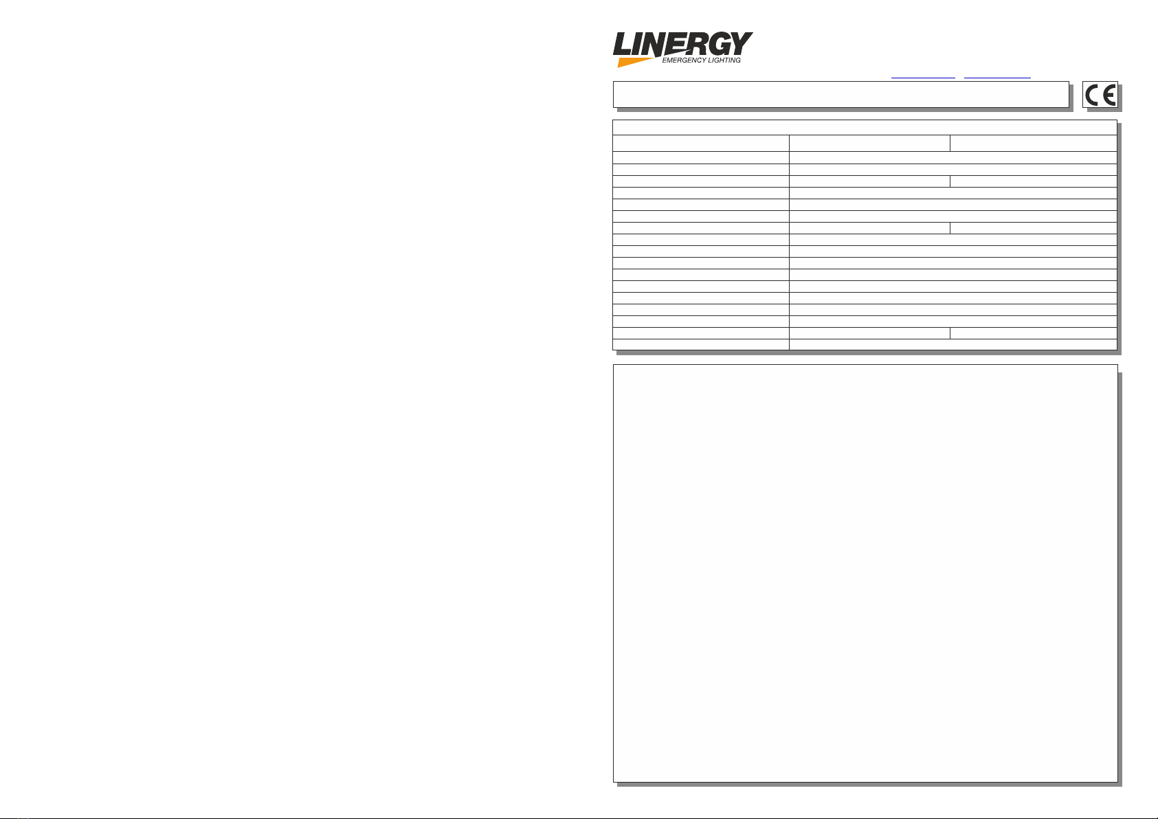
WATERPROOF NON MAINTAINED EMERGENCY LUMINAIRES
Aluminum, ABS/PC, PC
OPERATION TEMPERATURE RANGE
RELATIVE HUMIDITY
EXTERNAL DIMENSIONS
CONSTRUCTION MATERIALS
TYPICAL WEIGHT
GUARANTEE
OPERATION VOLTAGE
MAXIMUM POWER CONSUMPTION
BATTERY (Pb)
CHARGING TIME
INDICATIONS - CONTROLS
BATTERY PROTECTION
MINIMUM AUTONOMOUS DURATION
DEGREES OF COVER PROTECTION
PRODUCED IN ACCORDANCE WITH
EMERGENCY ILLUMINATION
LIGHT SOURCE
24h
Power indicator, battery charge indicator, TEST button
From overcharge and deep discharge
IP65
o
5 to 40 C
Up to 95%
3 years (1 year for the battery)
180 min90 min
3200lm
White power LEDs
6440gr.4250gr.
EN 60598-1, EN 60598-2-22, ΕΝ 55015, ΕΝ 61547, ΕΝ 61000-3-2, ΕΝ 61000-3-3
220-240V AC/50-60Hz
2x12V/7Ah12V/7Ah
307 x 100 x 350 mm.
TECHNICAL CHARACTERISTICS (for LED MODULE Specifications see page 2)
DU239P13EGS DU239P30EGS
13W/13.6VA
GB
LINERGY S.R.L.
VIA ALCIDE DE GASPERI, 9
ACQUAVIVA PICENA (AP) 63075 ITALY
TEL.: +39 0735 5974
FAX: +39 0735 597474
www.linergy.it info@linergy.it-
ISTDUALLED_V2-R2

Page 3 from 3
INSTALLATION PROCEDURE (For wall mounting only)
1. Use the supplied mounting accessories to mount the device (Fig1).
2. Remove the four cover retaining screws (Fig 1).
3. Install the battery cable connectors to the batteries taking care of the polarity, black cable (-)
and red cable (+).
4. Always use in any case round mains cable, with external diameter of 6-9mm (H05RN-F
type 2x1mm² or any other type, at least equal to it’s mechanical and electrical
properties). ATTENTION!! The cable must not be deformed in any way (This
requirement is important to ensure the tightness isolation IP65). Install the cable gland,
pass the round cable through and tighten it all the way.
5. Connect the cables to the respective positions in the terminal block L for phase and N for
neutral.
6. Reinstall the front cover and fasten the retaining screws. (Tightening torque 1Nm).
Pay attention to the 4 sealing o-rings.
WARNING!!
After the installation has finished, charge the batteries for at least 24 hours so as to
obtain the rated autonomy duration.
Page 2 from 3
case of less time than the minimum
autonomy duration the batteries must be
replaced. If the measured time is
considerably less than the minimum
autonomy duration contact the installer.
The replacement of the battery and the
light source must be done using parts of
the same type, by the manufacturer or by a
competent person.
5. In case of inactive use for a period greater
than 2 months, disconnect the battery by
pulling out the battery’s connector.
6. I s not allowed to discard batteries in t i
to common trash bins, they must be
discarded only in battery recycling
points. Do not incinerate.
Battery replacement
It can be done only by a competent person
and after the mains interruption.
1. Follow the step 2 of the installation
procedure.
2. Disconnect the cables and remove the old
battery.
3. Connect the new battery with the same type
(step 3 of the installation procedure) and
place it in the position of the old one.
4. Follow the step 6 of the installation
procedure and power the device.
(*) Non Maintained operation: The luminaire lights
its illumination source, only in power supply’s
failure.
Maintained operation: The luminaire lights its
illumination source, when it is powered by the
mains power supply or not.
NOTE: LED= Light Emitting Diode
LABELING EXPLANATION:
X: Self contained
0: Non Maintained (*)
A: Including test device
90: 1.5 hour duration
180: 3 hours duration
The light source contained in this luminaire shall only be replaced by the manufacturer, or
his agent, or a similar qualified person.
NOTE! The light source is non-user replaceable.
INDICATION LED STATUS (with the mains power supply connected)
CHARGE POWER
Disconnected battery / not charging
Charged battery Normal operation mode
No mains power supply
Indicator ONIndicator OFF
LED CHARACTERISTICS
Linergy s.r.l.
Cable connection between main pcb and led module
Manufacturer
Model Number
Voltage Range
Connections
Nominal Power
Temperature (tc)
DU239P13EGS DU239P30EGS
68 °C max.
17.5-20.5V
14W
1005183
TEST
button
Fig. 1
Power
indicator
Mounting holes
Charge
indicator
Cover
retaining
screws
4L
N
3
ISTDUALLED_V2-R2ISTDUALLED_V2-R2
GENERALE
INSTALLAZIONE
FUNZIONAMENTO
OPZIONE DIMMER
ΑΤΤΕΝZIONE!!!
Pagina 1 di 3
LAMPADA DI EMERGENZA A LED NON PERMANENTE
Alluminio, ABS/PC, PC
TEMPERATURA DI FUNZIONAMENTO
UMIDITA’ RELATIVA
DIMENSIONI
MATERIALI
PESO
GARANZIA
ALIMENTAZIONE
ASSORBIMENTO MASSIMO
BATTERIA (Pb)
TEMPO DI RICARICA
SEGNALAZIONE
BATTERY PROTECTION
AUTONOMIA
CLASSE DI PROTEZIONE
NORMATIVA DI RIFERIMENTO
FLUSSO LUMINOSO
SORGENTE LUMINOSA
24h
Indicatore di alimentazione, indicatore di carica della batteria, pulsante TEST
Da sovraccarico e scarica profonda
IP65
o
5 to 40 C
Superiore al 95%
3 anni (1 anno per le batterie)
180 min90 min
3200lm
LED di alimentazione bianchi
6440gr.4250gr.
EN 60598-1, EN 60598-2-22, ΕΝ 55015, ΕΝ 61547, ΕΝ 61000-3-2, ΕΝ 61000-3-3
220-240V AC/50-60Hz
2x12V/7Ah12V/7Ah
307 x 100 x 350 mm.
CARATTERISTICHE TECNICHE (per le specifiche del MODULO LED, vedere pagina 2)
DU239P13EGS DU239P30EGS
13W/13.6VA
IT
LINERGY S.R.L.
VIA ALCIDE DE GASPERI, 9
ACQUAVIVA PICENA (AP) 63075 ITALY
TEL.: +39 0735 5974
FAX: +39 0735 597474
www.linergy.it info@linergy.it-
Questi apparecchi sono utilizzati laddove è
necessaria luce di emergenza. Ogni
apparecchio d'illuminazione deve essere
collegato alla rete elettrica. Nel normale
funzionamento gli indicatori di carica sono
accesi per indicare che la batteria è in carica.
In caso di mancanza di alimentazione gli
indicatori si spengono e l'apparecchio si
accende automaticamente in modalità
emergenza. Quando viene ripristinata
l'alimentazione di rete, il dispositivo passa al
normale funzionamento.
Per installare l'apparecchio di illuminazione
seguire le istruzioni di installazione a pagina
3.
Quando il dispositivo è alimentato dalla rete,
e la batteria è connessa, gli indicatori 'power'
e 'charge' sono accesi. L'indicatore "charge"
indica la batteria è in ricarica. Se non si
accende, probabilmente, le batterie sono
disconnesse. Se non si accende e le batterie
sono collegate, contattare il tecnico.
L’indicatore di alimentazione (power)
conferma il corretto collegamento alla rete. Il
pulsante TEST, ha un duplice uso. Se
premuto mentre il dispositivo è collegato alla
rete elettrica, si simula l'interruzione di
Quando l'apparecchio è in modalità di
emergenza, con pressioni corrispondenti del
pulsante, possiamo scegliere l'illuminazione del
100%, 50%, 33% o spento. Questa opzione è
annullata quando la rete viene ripristinata.
corrente, mediante l'accensione delle lampade
per 3 ''.
In questo modo, possiamo il funzionemento
delle lampade come indicato al paragrafo 3.
1. Operazioni per l'installazione, manutenzione
o il test deve essere effettuato solo da
personale autorizzato.
2. Il dispositivo deve essere collegato all’
alimentazione di rete tramite un fusibile,
(dipende dal carico di potenza).
3. Si consiglia di controllare ogni mese il
LED di indicazione per la ricarica della batteria,
premendo il pulsante TEST per verificare il
circuito di emergenza e le lampade.
4. Si consiglia di controllare ogni 6 mesi la
durata minima di autonomia di scollegare
l'alimentazione di rete. Verificare il tempo di
accensione delle lampade.
ISTDUALLED_V2-R2

Pagina 3 di 3
PROCEDURA DI INSTALLAZIONE (Solo per montaggio a parete)
Pagina 2 di 3 ISTDUALLED_V2-R2
NOTA: LED
ETICHETTA:
X: SA
0: SE (*)
A: Test dell’apparecchio
90: 1.5 ore
180: 3 ore
NOTA! La sorgente luminosa non è sostituibile dall'utente.
INDICAZIONI DEL LED (collegata alla rete di alimentazione)
CARICA ALIMENTAZIONE
Batteria scollegata / non in carica
Batteria carica Modalità di funzionamento normale
Nessuna alimentazione di rete
Indicatore ONIndicatore OFF
CARATTERISTICHE
Linergy s.r.l.
Connessione via cavo tra il pcb principale e il modulo led
Manufacturer
Model Number
Voltage Range
Connections
Nominal Power
Temperature (tc)
DU239P13EGS DU239P30EGS
68 °C max.
17.5-20.5V
14W
1005183
TEST
Pulsante
Fig. 1
Alimentazione
Indicatore
Fori di montaggio
Carica
Indicatore
Viti del
coperchio
4L
N
3
Se l’autonomia non corrisponde sostituire
le batterie. Se il l’autonomia è
considerevolmente inferiore al minimo
contattare l'installatore.
La sostituzione della batteria e della fonte
di luce deve essere eseguita utilizzando
parti fornite dal produttore.
5. In caso di non utilizzo per un periodo
maggiore di 2 mesi, scollegare la batteria
estraendo il connettore.
6. Non è consentito smaltire le batterie nei
bidoni della spazzatura comuni, devono
essere smaltite solo nei centri di raccolta.
Non incenerire.
(*) Funzionamento (SE) solo emergenza:
la lampada si accende solo quando c’è un
interruzione dell’energia elettrica che la
alimenta.
Funzionamento (SA) permanente: la
lampada rimane sempre accesa sia in
presenza che in assenza di rete.
La sorgente luminosa contenuta in questo apparecchio deve essere sostituita da
personale qualificato.
1. Utilizzare gli accessori di montaggio in dotazione per montare il dispositivo (Fig. 1).
2. Rimuovere le quattro viti di fissaggio del coperchio (Fig. 1).
3. Installare i connettori del cavo della batteria facendo attenzione alla polarità, cavo nero (-)
e cavo rosso (+).
4. Utilizzare sempre un cavo di alimentazione rotondo, con un diametro di 6-9 mm (H05RN-F
tipo 2x1mm² o qualsiasi altro tipo). ATTENZIONE!! Il cavo non deve essere deformato in
alcun modo (Questo
requisito è importante per garantire l'isolamento di tenuta IP65). Installare il pressacavo,
passare il cavo tondo attraverso e serrarlo fino in fondo.
5. Collegare i cavi alle rispettive posizioni nella morsettiera L per fase e N per neutro.
6. Reinstallare il coperchio anteriore e serrare le viti di fissaggio. (Coppia di serraggio 1 Nm).
Prestare attenzione ai 4 o-ring di tenuta.
AVVERTIMENTO!!
Al termine dell'installazione, caricare le batterie per almeno 24 ore in modo da ottenere
la durata nominale di autonomia.
ISTDUALLED_V2-R2
Sostituzione della batteria.
Può essere fatto solo da personale
competente e dopo l'interruzione di rete.
1. Seguire il passaggio 2 della procedura
di installazione.
2. Scollegare i cavi e rimuovere la vecchia
batteria.
3. Collegare la nuova batteria (passaggio 3
della procedura di installazione) e
posizionarla nella come quella sostituita.
4. Seguire il passaggio 6 della procedura
di installazione e alimentare il dispositivo ..
Si consiglia di controllare ogni mese il
LED di indicazione per la ricarica della
batteria.
This manual suits for next models
1
Table of contents
Languages:
Other Linergy Lantern manuals


Popular Lantern manuals by other brands


shada
shada 1000436 instruction manual

BEGA
BEGA 84 036 Instructions for use

BEGA
BEGA 33 596 Instructions for use

Dale Tiffany
Dale Tiffany GT701162 Assembly instructions

Wagan
Wagan Brite Nite Pop-Up USB Lantern user manual

Eaton
Eaton Crouse-Hinds Pauluhn DLLA M2 Series Installation & maintenance information