LinMot C1250-CM-XC-0S User manual

May 2019
Manual
EtherNet/IP Interface User Manual
Doc.: 0185-1165-E_5V2_MA_EtherNet-IP-CIP-Sync

2 / 33 NTI AG / LinMot
© 2019 NTI AG
This work is protected by copyright.
Under the copyright laws, this publication may not be reproduced or transmitted in any form, electronic or
mechanical, including photocopying, recording, microfilm, storing in an information retrieval system, not even for
didactical use, or translating, in whole or in part, without the prior written consent of NTI AG.
LinMot® is a registered trademark of NTI AG.
Note
The information in this documentation reflects the stage of development at the time of press and is therefore
without obligation. NTI AG reserves itself the right to make changes at any time and without notice to reflect
further technical advance or product improvement.
NTI AG
LinMot
Bodenaeckerstrasse 2
CH-8957 Spreitenbach
Tel.: +41 56 419 91 91
Fax.: +41 56 419 91 92
Email: office@LinMot.com
Homepage: www.LinMot.com

3 / 33NTI AG / LinMot
1. System overview ............................................................................................................... 4
1.1 References ................................................................................................................. 4
2. Connection to the EtherNet/IP Network ...................................................................... 4
2.1 Pin Assignment of the Connectors X17-X18 ........................................................... 4
2.2 Default IP Address Settings ...................................................................................... 5
2.3 RT Bus LEDs .............................................................................................................. 5
3. Setup in the PLC ............................................................................................................... 6
3.1 RSLinx Classic ............................................................................................................ 6
3.2 LinMot Configuration in the PLC ............................................................................. 7
3.3 Getting started with the Watch Window ................................................................ 12
3.3.1 Control Word ..................................................................................................... 13
3.3.2 Motion Command Interface ............................................................................. 18
4. EtherNet/IP Parameters ................................................................................................. 25
4.1 EtherNet/IP Dis-/Enable .......................................................................................... 25
4.2 EtherNet/IP \ Ethernet Configuration \ IP Configuration Mode ......................... 26
4.3 EtherNer/IP \ EtherNet Configuration \ IP Configuration ................................... 26
5. Realtime IO Data Mapping ............................................................................................ 26
5.1 Exclusive Owner, CIP Sync, 0x78/0x64 ................................................................. 26
5.1.1 Configuration AssemblyInstance 1 ................................................................ 27
5.1.2 O->T AssemblyInstance 120 (0x78) ................................................................ 27
5.1.3 T->O AssemblyInstance 100 (0x64) ................................................................ 29
5.2 Legacy: Exclusive Owner, As_0x28_0x18 ............................................................. 29
5.2.1 O->T AssemblyInstance 40 ............................................................................. 30
5.2.2 T->O AssemblyInstance 24 ............................................................................. 30
6. CIP Sync Streaming ....................................................................................................... 31

4 / 33 NTI AG / LinMot
1 System overview
The LinMot Ethernet/IP drives have the following functionalities:
Device Property
Value / Remark
Minimal EtherNet/IP cycle time
1 ms
Minimal CIP Sync based streaming period
2 ms
DHCP
Supported
EDS
Supported
IEEE1588 (CIP-Sync)
with Rockwell PLC
DLR Support (Device Level Ring Protocol)
Yes
EtherNet/IP is a real time Ethernet protocol based on the standard Ethernet protocols
TCP/IP and UDP/IP.
For further information on EtherNet/IP please visit: http://www.odva.org
1.1 References
All user manuals are distributed with the LinMot-Talk configuration software. The newest
version can also be downloaded from the LinMot homepage in the download section.
Ref
Title
Source
1
0185-1093-E_XXX_MA_MotionCtrlSW-
SG5-SG7
www.linmot.com
2
0185-1074-E_XXX_MA_Drive-
Configuration-Over-Fieldbus-SG5-SG7
www.linmot.com
2 Connection to the EtherNet/IP Network
2.1 Pin Assignment of the Connectors X17-X18
The Ethernet/IP connector is a standard RJ45 female connector with a pin assignment
as defined by EIA/TIA T568B:

5 / 33NTI AG / LinMot
X17 - X18
RealTime Ethernet Connector
Pin
Wire color code
Assignment 100
BASE-TX
1
2
3
4
5
6
7
8
case
WHT/ORG
ORG
WHT/GRN
BLU
WHT/BLU
GRN
WHT/BRN
BRN
-
Rx+
Rx-
Tx+
-
-
Tx-
-
-
-
RJ-45
Use standard patch cables (twisted pair, S/UTP, AWG26) for
wiring. This type of cable is usually referred to as a “Cat5e-
Cable”.
2.2 Default IP Address Settings
The default IP address is 192.168.1.xxx, where the last byte xxx is defined via the two
hex switches S1 and S2. S1 sets the high and S2 the low digit.
S1, S2
IP Selectors
S1
S2
Bus ID High (0h...Fh)
Bus ID Low (0h...Fh)
The switch value S1 = S2 = 0 (factory default setting) is a special
configuration which acquires the IP address via DHCP.
2.3 RT Bus LEDs
RT Bus LEDs
Function
The RT Bus LEDs have no
function.
They are always turned off.

6 / 33 NTI AG / LinMot
3 Setup in the PLC
Use only AB PLC firmware 18.0 or higher!
The following steps describe the integration of a LinMot Ethehernet/IP drive in the PLC.
In the example an Allen Bradley master PLC is used. RSLinx tool can only be used to
see if the device is on the network and under which IP-address it can be accessed. The
whole configuration is done in the PLC, which is described in chapter 3.2.
3.1 RSLinx Classic
In the RSLinx the LinMot device should occur under the defined IP address as
“Unrecognized Device”
LinMot Device with the IP address 192.168.1.89. in the RSLinx tool.

7 / 33NTI AG / LinMot
LinMot device properties
3.2 LinMot Configuration in the PLC
The LinMot Drive must be configured in the PLC using an EDS-File.
To configure the LinMot with the EDS File, the EDS-File must be downloaded into the
configuration software of the PLC. In the RSLogix 5000 there is the EDS Hardware
Installation Tool, which is used for the installation. It can be found in the menu under
"Tools".
Then you can click next until the "Options" window is shown. In this window "Register
an EDS file(s)" has to be selected.

8 / 33 NTI AG / LinMot
In the "Registration" window, “Register a directory of EDS files” has to be selected. The
path of the directory is:
../LinMot-TalkX.X BuildX/Firmware/Interfaces/EtherNetIP_NX/EDS
After this selection you can click next and finish the EDS Hardware Installation.

9 / 33NTI AG / LinMot
When the EDS-Files are downloaded in the PLC configuration software, the LinMot can
be configured in the I/O configuration section, in the Ethernet section as a new module.
In the section “Module Type Vendor Filters” there is the Vendor “NTI Limited”, where the
drive can be selected.
After creating a new module, on the Tab "General", under "Module Definition" using the
button "Change ...", two communication types can be chosen.
Exclusive Owner, CIPSync, 0x78/0x64: Realtime IO with configuration module and
CIP Sync Timestamp (Default)
Legacy: Exclusive Owner, As_0x28_0x18: Realtime IO with configuration module,
only for retrofit without CIP Sync functionality, no streaming supported
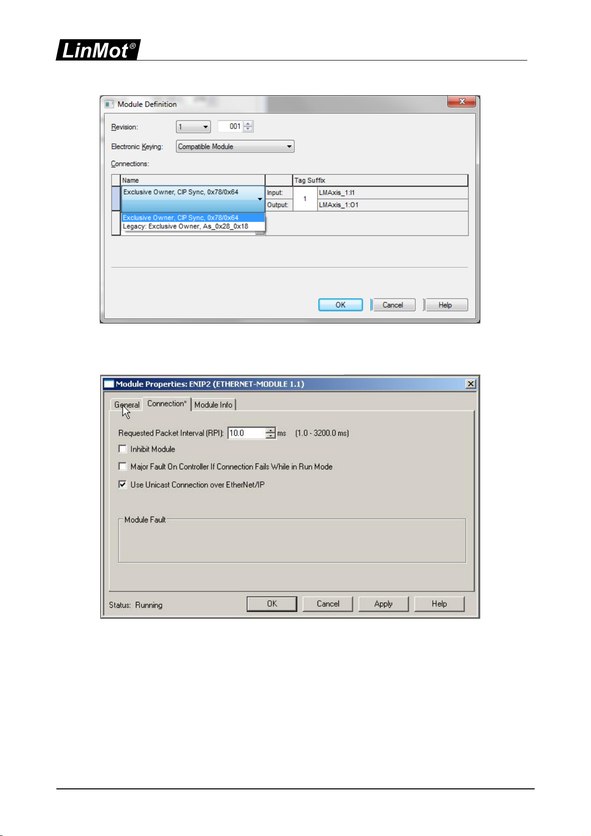
10 / 33 NTI AG / LinMot
In the Connection tab of the Module Properties the desired cycle time is specified in the
range between 1ms and 3200ms.
Only Unicast Connection is supported.
To add more modules the EDS-File registration does not need to be repeated.
If the setup was successful the LinMot module status will be "Running".

11 / 33NTI AG / LinMot
The table below shows which EDS-File is for which Drive. If the full EDS folder is loaded
in the configuration tool, the names of the Drives are visualized.
File Name
Art.-Number
Drive Type
C1250CMXC0S.eds
0150-2900
C1250CMXC0S
C1250CMXC1S.eds
0150-2901
C1250CMXC1S
12 / 33 NTI AG / LinMot
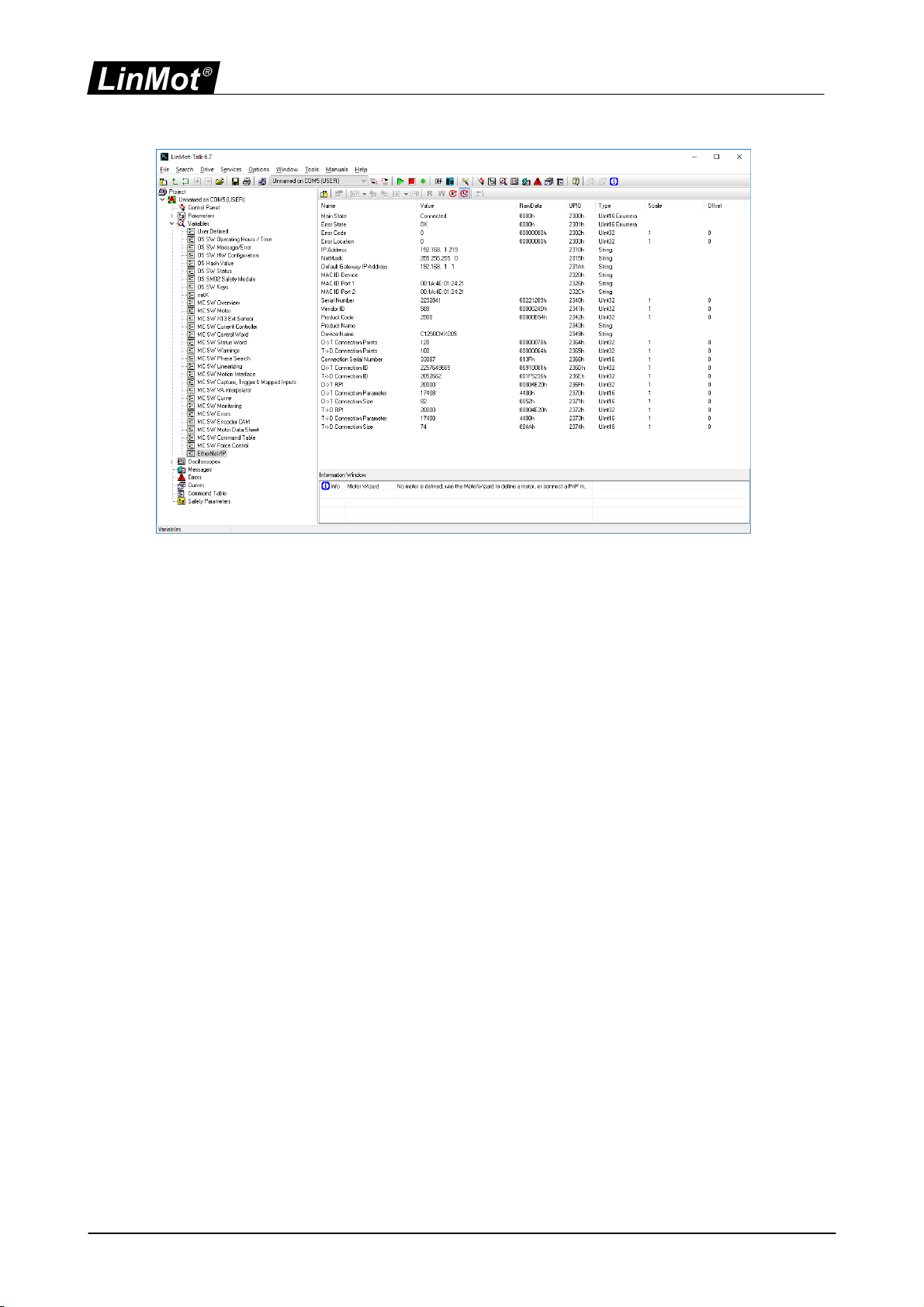
In the LinMot-Talk configuration software the EtherNet/IP connection state is shown in
"Variables\EtherNet/IP". If set up correctly, the "Main State" should change to
"Connected" after some time when powered on.
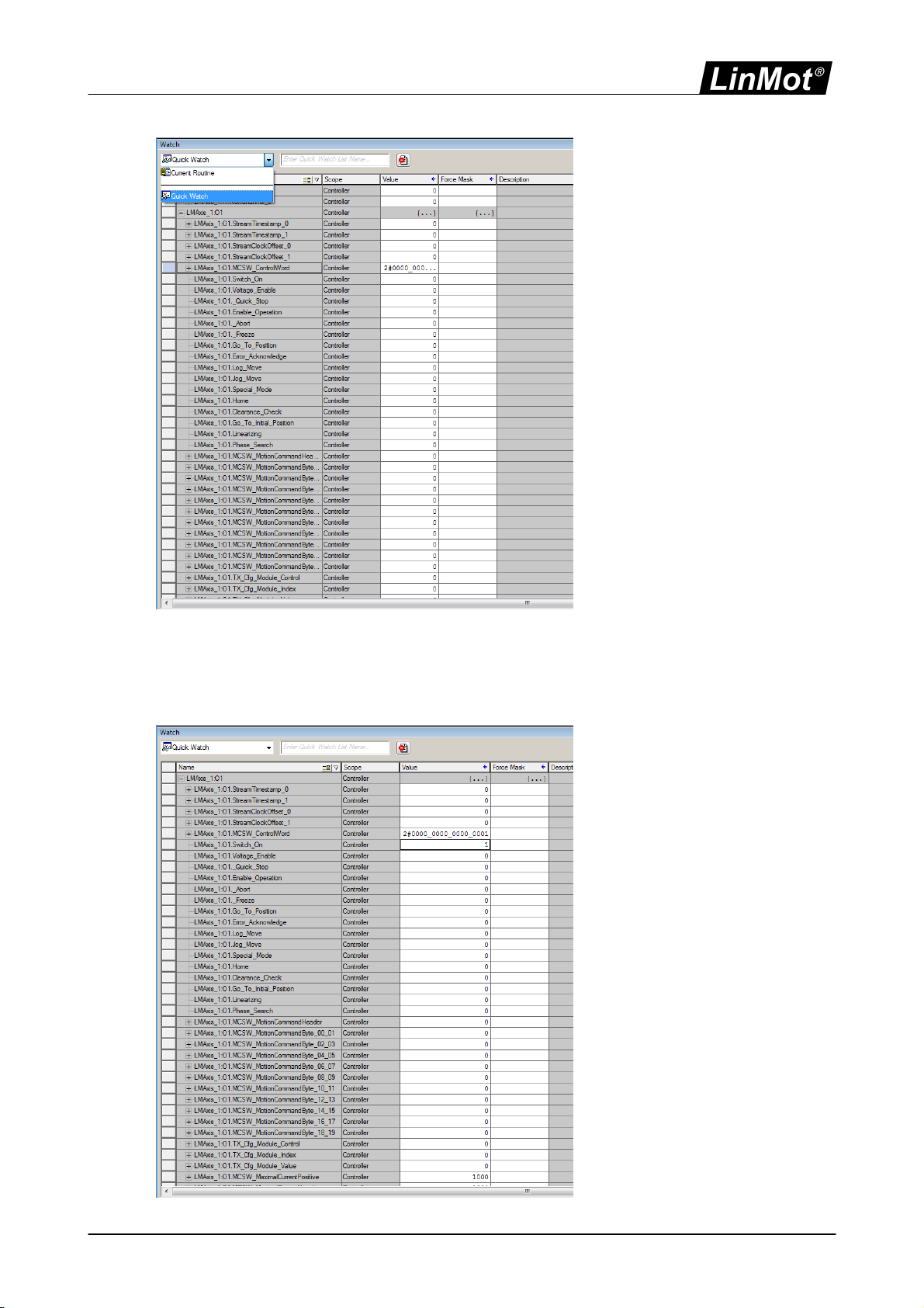
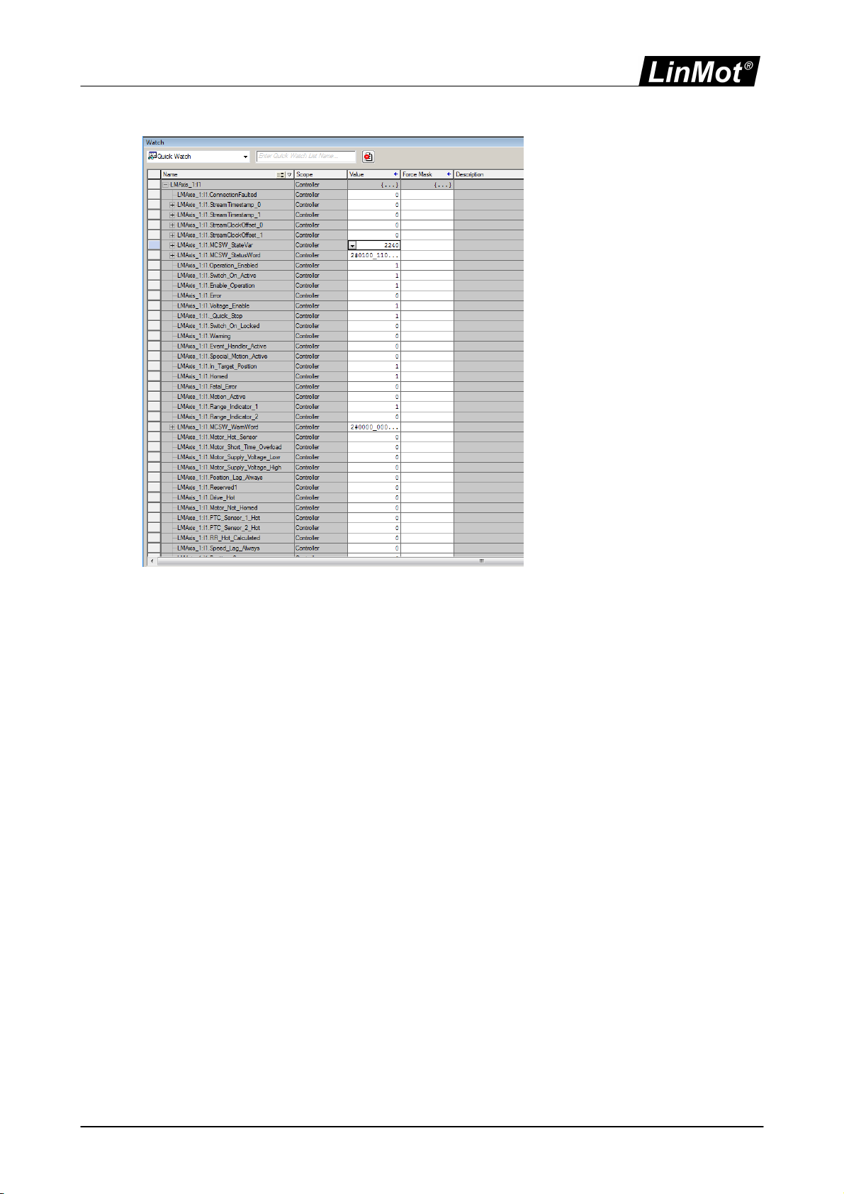
3.3 Getting started with the Watch Window
In this section the basics of the LinMot device handling are explained. Instead of
programming the LinMot drive, data can be directly set with the watch window. For the
next steps, map the modules input data and output data in the quick watch window as
shown below.
In the following examples it is assumed that a motor has been configured, the power
supply is on and the drive is correctly embedded in the Ethernet/IP network.
13 / 33NTI AG / LinMot
3.3.1 Control Word
The Control Word is mapped to the output data word 4 (byte 16/17). If setting this value
to 1 the “Switch On” bit (bit 0) of the Control Word is set.
14 / 33 NTI AG / LinMot
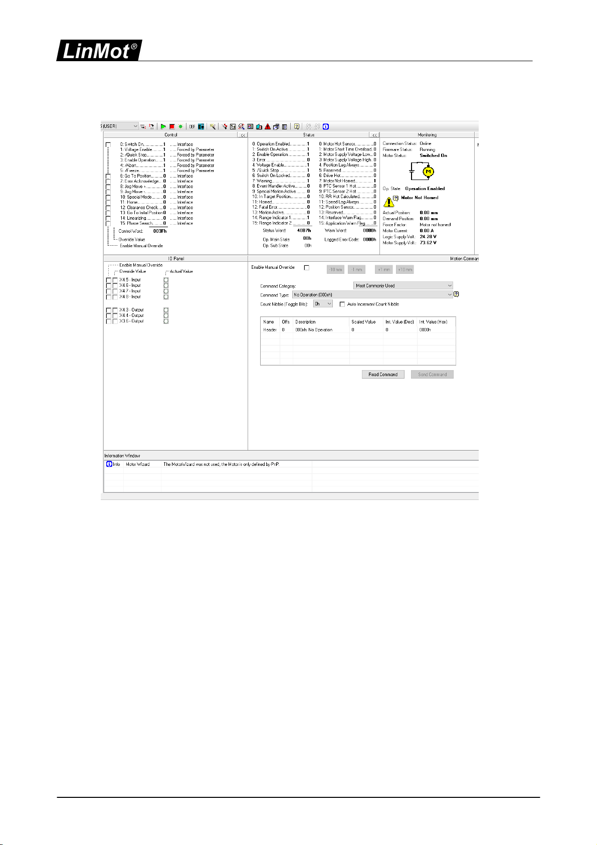
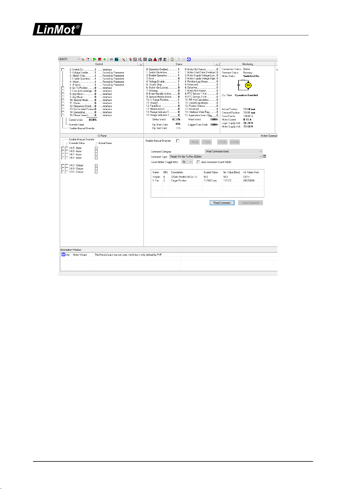
This can also be monitored on the Control Panel of the LinMot-Talk software.
Setting the Control Word to 2049 (0x0801) sets also the “Home” bit (Bit 11) in the
Control Word. Wait until the input word 4 “State Var” has the value 2319 (0x090F) Main
State 9 (Homing) Sub State 0x0F (Homing finished).

15 / 33NTI AG / LinMot

16 / 33 NTI AG / LinMot
The Control Word can then be set to 1 again, the drive will change to Main State 8
(Operation Enabled) Sub State 0xC0 (Homed and In Target Position), the corresponding
State Var has the value 2240.
17 / 33NTI AG / LinMot

18 / 33 NTI AG / LinMot
3.3.2 Motion Command Interface
Other output data are mapped to the “Motion Command
Interface” (MCSW_MotionCommandHeader and MCSW_MotionCommandByte_0 ... 19).
The first word (MCSW_MotionCommandHeader) is the motion command header, the
remaining (MCSW_MotionCommandByte 0 ... 19) are the command specific motion
parameters. In the next example we will set up a “Predef VAI Go To Pos (020xh)” Motion
Command. First we set the target position low word
(MCSW_MotionCommandByte_00_01) to 0 then the target position high word
(MCSW_MotionCommandByte_02_03) to 2 and the motion command header
(MCSW_MotionCommandHeader) to 513 (0x0201).

19 / 33NTI AG / LinMot
20 / 33 NTI AG / LinMot
Press the “Read Command” button to see the sent command.
We will use the same command to move back to 0mm. Change the target position high
word to 0. Then change the count nibble in the motion command header to 0.
This manual suits for next models
1
Table of contents
Other LinMot DC Drive manuals

LinMot
LinMot E1130-DP-HC User manual

LinMot
LinMot C1250-EC-XC-0S User manual

LinMot
LinMot C1150-SE-XC-0S User manual

LinMot
LinMot C1251-MI-XC-2S-XE User manual

LinMot
LinMot E1100-CO Instruction Manual

LinMot
LinMot C1250-PD-XC-0S User manual

LinMot
LinMot B1100 Series User manual

LinMot
LinMot B1100-PP User manual

LinMot
LinMot E1250-LU-UC User manual

LinMot
LinMot E1100-GP User manual


