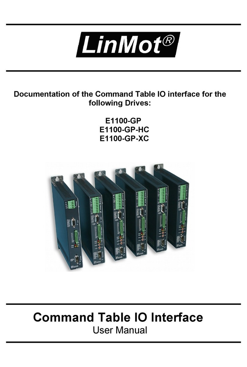
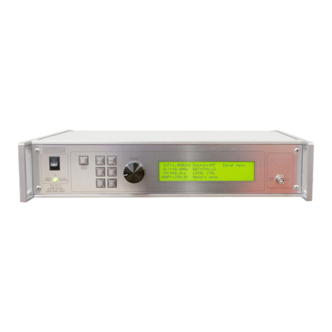
LinMot B1100 Series User manual

Sinoide Application SW
Documentation of the Sinoide Application SW
-E1100 / B1100 Drive Series
Sinoide Application SW
User Manual

Sinoide Application
LinMot
© 2013 NTI AG
This work is protected by copyright.
Under the copyright laws, this publication may not be reproduced or transmitted in any form, electronic or mechanical, including
photocopying,
recording, microfilm, storing in an information retrieval system, not even for didactical use, or translating, in whole or in
part, without the prior written consent of NTI AG.
LinMot® is a registered trademark of NTI AG.
Note
The information in this documentation reflects the stage of development at the time of press and is therefore without obligation.
NTI AG. reserves itself the right to make changes at any time and without notice to reflect further technical advance or product
improvement.
Document Version 3.18 / Whp, December 2 13
Page 2/15 User Manual Sinoide Application / 6/12/2 13 NTI AG / LinMot

Sinoide Application
LinMot
TABLE OF CONTENT
SYSTEM OVERVIEW............................................................................................................4
1.1 REFERENCES.........................................................................................................................4
1.2 DEFINITIONS, ITEMS, SHORTCUTS.............................................................................................4
1.3 DATA TYPES.........................................................................................................................4
2 INSTALLATION ON DRIVE..............................................................................................5
3 SINOIDE FUNCTIONALITY..............................................................................................6
3.1 OVERVIEW MOTION COMMANDS.............................................................................................6
3.2 DETAILED MOTION COMMAND DESCRIPTION.............................................................................7
3.2.1 Sin VA Go To Pos (3E0xh)........................................................................................7
3.2.2 Sin VA Increment Demand Pos (3E1xh)....................................................................7
3.2.3 Sin VA Go To Pos rom Actual Pos (3E4xh)............................................................7
3.2.4 Sin VA Increment Actual Pos (3E6xh).......................................................................7
3.2.5 Sin VA Go To Pos On Rising Trigger Event (3EAxh)...............................................8
3.2.6 Sin VA Increment Demand Pos On Rising Trigger Event (3EBxh)...........................8
3.2.7 Sin VA Go To Pos On alling Trigger Event (3ECxh)..............................................8
3.2.8 Sin VA Increment Demand Pos On alling Trigger Event (3EDxh).........................9
3.2.9 Bestehorn VAJ Go To Pos (3 0xh)...........................................................................9
3.2.10 Bestehorn VAJ Increment Demand Pos (3 1xh).....................................................9
3.2.11 Bestehorn VAJ 16 Bit Go To Pos (3 2xh)...............................................................9
3.2.12 Bestehorn VAJ Go To Pos rom Actual Pos (3 4xh)...........................................10
3.2.13 Bestehorn VAJ Increment Actual Pos (3 6xh)......................................................10
3.2.14 Bestehorn VAJ Go To Pos On Rising Trigger Event (3 Axh)...............................10
3.2.15 Bestehorn VAJ Increment Demand Pos On Rising Trigger Event (3 Bxh)..........11
3.2.16 Bestehorn VAJ Go To Pos On alling Trigger Event (3 Cxh).............................11
3.2.17 Bestehorn VAJ Increment Demand Pos On alling Trigger Event (3 Dxh)........12
4 SETPOINT GENERATION...............................................................................................13
4.1 SINE VA MOTION...............................................................................................................13
4.1.1.1 Para eters and Output......................................................................................13
4.2 BESTEHORN VAJ MOTION...................................................................................................14
4.2.1.1 Para eters and Output......................................................................................14
5 CONTACT ADDRESSES...................................................................................................15
Page 3/15 User Manual Sinoide Application / 6/12/2 13 NTI AG / LinMot

Sinoide Application
LinMot
System Overview
This user Manual describes the Sinoide Application SW functionality of the LinMot E11 /
B11 drives.
1.1 References
Ref Title Source
1 Installation_Guide_E11 .pdf www.linmot.com
2 Installation_Guide_B11 .pdf www.linmot.com
3 Usermanual_LinMot-Talk_4.pdf www.linmot.com
The documentation is distributed with the LinMot-Talk configuration software or can be
downloaded from the Internet from the download section of our homepage.
1.2 Definitions, Items, Shortcuts
Shortcut Meaning
LM LinMot linear motor
OS Operating system (Software)
MC (SW) Motion Control (Software)
Intf Interface (Software)
Appl Application (Software)
VAI VA-Interpolator (Max velocity limited acceleration position interpolator)
Pos Position
Vel Velocity
Acc Acceleration
Dec Deceleration
UPID Unique Parameter ID (16 bit)
1.3 Data types
Type Range/Format Num of bytes
Bool Boolean, False/True 1/8
Byte ..255 1
Char ASCII 1
String Array of char last char = h X
SInt16 -32768..32767 2
UInt16 ..65535 2
SInt32 -2147483648..2147483647 4
UInt32 ..4294967295 4
Page 4/15 User Manual Sinoide Application / 6/12/2 13 NTI AG / LinMot

Sinoide Application
LinMot
2 nstallation on Drive
For installing the Sinoide firmware on the drive, start the LinMot-Talk software and press the
install firmware button . Choose the file “Firmware_Buildxxxxxxxx.sct” and press “Open”.
The wizard will guide you through the installation. When asking for the application software
choose “Sinoide”
Press ok and follow the rest of the wizard.
Page 5/15 User Manual Sinoide Application / 6/12/2 13 NTI AG / LinMot

Sinoide Application
LinMot
3 Sinoide Functionality
The Sinoide Application SW is a MC Motion Command Interface extension, with the Sinoide
functionality. Additional the Autostart application is included.
3.1 verview Motion Commands
Page 6/15 User Manual Sinoide Application / 6/12/2 13 NTI AG / LinMot
Master
ID
Sub
ID
E
1
1
B
1
1
Description
3Eh h X X Sin VA Go To Pos
1h X X Sin VA Increment Demand Pos
4h X X Sin VA Go To Pos From Actual Pos
6h X X Sin VA Increment Actual Pos
Ah X X Sin VA Go To Pos On Rising Trigger Event
Bh X X Sin VA Increment Demand Pos On Rising Trigger Event
Ch X X Sin VA Go To Pos On Falling Trigger Event
Dh X X Sin VA Increment Demand Pos On Falling Trigger Event
3Fh h X X Bestehorn VAJ Go To Pos
1h X X Bestehorn VAJ Increment Demand Pos
2h X X Bestehorn VAJ 16 Bit Go To Pos
4h X X Bestehorn VAJ Go To Pos From Actual Pos
6h X X Bestehorn VAJ Increment Actual Pos
Ah X X Bestehorn VAJ Go To Pos On Rising Trigger Event
Bh X X Bestehorn VAJ Increment Demand Pos On Rising Trigger Event
Ch X X Bestehorn VAJ Go To Pos On Falling Trigger Event
Dh X X Bestehorn VAJ Increment Demand Pos On Falling Trigger Event

Sinoide Application
LinMot
3.2 Detailed Motion Command Description
3.2.1 Sin VA Go To Pos (3E0xh)
Name Byte
Offset
Description Type Unit
Header 3E xh: Sin VA Go To Pos UInt16 -
1. Par 2 Target Position SInt32 .1 um
2. Par 6 Maximal Velocity UInt32 1E-6 m/s
3. Par 1 Acceleration UInt32 1E-5 m/s2
Half period sine motion profile, regarding the limitations of maximal acceleration and maximal
velocity.
3.2.2 Sin VA ncrement Demand Pos (3E1xh)
Name Byte
Offset
Description Type Unit
Header 3E1xh: Sin VA Increment Demand Pos UInt16 -
1. Par 2 Position Increment SInt32 .1 um
2. Par 6 Maximal Velocity UInt32 1E-6 m/s
3. Par 1 Acceleration UInt32 1E-5 m/s2
Half period sine motion profile, regarding the limitations of maximal acceleration and maximal
velocity. The new Target Position value will be determined by the firmware. It is calculated by
adding the Position Increment argument to the Demand Position value (relative move). The
command execution starts immediately when the command has been sent.
3.2.3 Sin VA Go To Pos From Actual Pos (3E4xh)
Name Byte
Offset
Description Type Unit
Header 3E4xh: Sin VA Go To Pos From Actual Pos UInt16 -
1. Par 2 Target Position SInt32 .1 um
2. Par 6 Maximal Velocity UInt32 1E-6 m/s
3. Par 1 Acceleration UInt32 1E-5 m/s2
Half period sine motion profile, regarding the limitations of maximal acceleration and maximal
velocity. The command execution starts immediately when the command has been sent. This
command should be used if the Actual Position does not match with the current Demand
Position value, but it can be assumed that the motor stands still (Actual Velocity assumed to
be zero, e.g. because the motor stands on a hard stop). This can happen after a Press
command, where the actual motor position is defined through external conditions and the
motor could not and had not to follow the demand position. By starting this command, the
former accepted difference between Actual Position and Demand Position can be eliminated.
3.2.4 Sin VA ncrement Actual Pos (3E6xh)
Name Byte
Offset
Description Type Unit
Header 3E6xh: Sin VA Increment Actual Pos UInt16 -
1. Par 2 Position Increment SInt32 .1 um
2. Par 6 Maximal Velocity UInt32 1E-6 m/s
3. Par 1 Acceleration UInt32 1E-5 m/s2
Page 7/15 User Manual Sinoide Application / 6/12/2 13 NTI AG / LinMot

Sinoide Application
LinMot
Half period sine motion profile, regarding the limitations of maximal acceleration and maximal
velocity. The new Target Position value will be determined by the firmware. It is calculated by
adding the Position Increment argument to the Actual Position value (relative move). The
command execution starts immediately when the command has been sent.
3.2.5 Sin VA Go To Pos On Rising Trigger Event (3EAxh)
Name Byte
Offset
Description Type Unit
Header EAxh: Sin VA Go To Pos On Rising Trigger Event UInt16 -
1. Par 2 Target Position SInt32 .1 um
2. Par 6 Maximal Velocity UInt32 1E-6 m/s
3. Par 1 Acceleration UInt32 1E-5 m/s2
This command defines a new sine motion command (see description of command 'Sin VA
Go To Pos (3E xh)'. The command will be started on each rising edge on the Trigger signal.
This command is used to synchronize the execution of the motion command to a hardware
signal. The command activates the Event Handler (see Status Word bit 8). The Event
Handler starts the new Sin VA motion on the rising trigger event. The Event Handler can be
deactivated by using the command 'Clear Event Evaluation ( 8xh)'. The trigger input must
be configured with parameter <UPID>$1 39.
3.2.6 Sin VA ncrement Demand Pos On Rising Trigger Event (3EBxh)
Name Byte
Offset
Description Type Unit
Header 3EBxh: Sin VA Increment Demand Pos On Rising
Trigger Event
UInt16 -
1. Par 2 Position Increment SInt32 .1 um
2. Par 6 Maximal Velocity UInt32 1E-6 m/s
3. Par 1 Acceleration UInt32 1E-5 m/s2
This command defines a new Sin VA motion command (relative move, see description of
command 'Sin VA Increment Demand Pos (3E1xh)'). The command will be started on each
rising edge on the Trigger signal. This command is used to synchronize the execution of the
motion command to a hardware signal. The command activates the Event Handler (see
Status Word bit 8). The Event Handler starts the new Sin VA motion on the rising trigger
event. The Event Handler can be deactivated by using the command 'Clear Event Evaluation
( 8xh)'. The trigger input must be configured with parameter <UPID>$1 39.
3.2.7 Sin VA Go To Pos On Falling Trigger Event (3ECxh)
Name Byte
Offset
Description Type Unit
Header ECxh: Sin VA Go To Pos On Falling Trigger Event UInt16 -
1. Par 2 Target Position SInt32 .1 um
2. Par 6 Maximal Velocity UInt32 1E-6 m/s
3. Par 1 Acceleration UInt32 1E-5 m/s2
This command defines a new Sin VA motion command (see description of command 'Sin VA
Go To Pos (3E xh)'). The command will be started on each falling edge on the Trigger
signal. This command is used to synchronize the execution of the motion command to a
hardware signal. The command activates the Event Handler (see Status Word bit 8). The
Page 8/15 User Manual Sinoide Application / 6/12/2 13 NTI AG / LinMot

Sinoide Application
LinMot
Event Handler starts the new Sin VA motion on the falling trigger event. The Event Handler
can be deactivated by using the command 'Clear Event Evaluation ( 8xh)'. The trigger input
must be configured with parameter <UPID>$1 39.
3.2.8 Sin VA ncrement Demand Pos On Falling Trigger Event (3EDxh)
Name Byte
Offset
Description Type Unit
Header 3EDxh: Sin VA Increment Demand Pos On Falling
Trigger Event
UInt16 -
1. Par 2 Position Increment SInt32 .1 um
2. Par 6 Maximal Velocity UInt32 1E-6 m/s
3. Par 1 Acceleration UInt32 1E-5 m/s2
This command defines a new Sin VA motion command (relative move, see description of
command 'Sin VA Increment Demand Pos ( E1xh)'). The command will be started on each
falling edge on the Trigger signal. This command is used to synchronize the execution of the
motion command to a hardware signal. The command activates the Event Handler (see
Status Word bit 8). The Event Handler starts the new Sin VA motion on the falling trigger
event. The Event Handler can be deactivated by using the command 'Clear Event Evaluation
( 8xh)'. The trigger input must be configured with parameter <UPID>$1 39.
3.2.9 Bestehorn VAJ Go To Pos (3F0xh)
Name Byte
Offset
Description Type Unit
Header 3F xh: Bestehorn VAJ Go To Pos UInt16 -
1. Par 2 Target Position SInt32 .1 um
2. Par 6 Maximal Velocity UInt32 1E-6 m/s
3. Par 1 Acceleration UInt32 1E-5 m/s2
4. Par 14 Jerk UInt32 1E-4 m/s3
Bestehorn Motion Profile, regarding the limitations maximal jerk, acceleration and maximal
speed.
3.2.10 Bestehorn VAJ ncrement Demand Pos (3F1xh)
Name Byte
Offset
Description Type Unit
Header 3F1xh: Bestehorn VAJ Increment Demand Pos UInt16 -
1. Par 2 Position Increment SInt32 .1 um
2. Par 6 Maximal Velocity UInt32 1E-6 m/s
3. Par 1 Acceleration UInt32 1E-5 m/s2
4. Par 14 Jerk UInt32 1E-4 m/s3
Bestehorn Motion Profile, regarding the limitations maximal jerk, acceleration and maximal
speed. The new Target Position value will be determined by the firmware. It is calculated by
adding the Position Increment argument to the Demand Position value (relative move). The
command execution starts immediately when the command has been sent.
3.2.11 Bestehorn VAJ 16 Bit Go To Pos (3F2xh)
Name Byte
Offset
Description Type Unit
Page 9/15 User Manual Sinoide Application / 6/12/2 13 NTI AG / LinMot

Sinoide Application
LinMot
Header 3F2xh: Bestehorn VAJ 16 Bit Go To Pos UInt16 -
1. Par 2 Target Position SInt16 Scaled
2. Par 4 Maximal Velocity UInt16 Scaled
3. Par 6 Acceleration UInt16 Scaled
4. Par 8 Jerk UInt16 Scaled
Bestehorn Motion Profile, regarding the limitations maximal jerk, acceleration and maximal
speed. With 16 bit motion parameters: UPID 1455h for Position, UPID 1456 for Maximal
Velocity, UPID 1457h for Acceleration and UPID 1458h for Jerk Scaling.
3.2.12 Bestehorn VAJ Go To Pos From Actual Pos (3F4xh)
Name Byte
Offset
Description Type Unit
Header 3F4xh: Bestehorn VAJ Go To Pos From Actual Pos UInt16 -
1. Par 2 Target Position SInt32 .1 um
2. Par 6 Maximal Velocity UInt32 1E-6 m/s
3. Par 1 Acceleration UInt32 1E-5 m/s2
4. Par 14 Jerk UInt32 1E-4 m/s3
Bestehorn Motion Profile, regarding the limitations maximal jerk, acceleration and maximal
speed. The command execution starts immediately when the command has been sent. This
command should be used if the Actual Position does not match with the current Demand
Position value, but it can be assumed that the motor stands still (Actual Velocity assumed to
be zero, e.g. because the motor stands on a hard stop). This can happen after a Press
command\c where the actual motor position is defined through external conditions and the
motor could not and had not to follow the demand position. By starting this command, the
former accepted difference between Actual Position and Demand Position can be eliminated.
3.2.13 Bestehorn VAJ ncrement Actual Pos (3F6xh)
Name Byte
Offset
Description Type Unit
Header 3F6xh: Bestehorn VAJ Increment Actual Pos UInt16 -
1. Par 2 Position Increment SInt32 .1 um
2. Par 6 Maximal Velocity UInt32 1E-6 m/s
3. Par 1 Acceleration UInt32 1E-5 m/s2
4. Par 14 Jerk UInt32 1E-4 m/s3
Bestehorn Motion Profile, regarding the limitations maximal jerk, acceleration and maximal
speed. The new Target Position value will be determined by the firmware. It is calculated by
adding the Position Increment argument to the Actual Position value (relative move). The
command execution starts immediately when the command has been sent.
3.2.14 Bestehorn VAJ Go To Pos On Rising Trigger Event (3FAxh)
Name Byte
Offset
Description Type Unit
Header 3FAxh: Bestehorn VAJ Go To Pos On Rising
Trigger Event
UInt16 -
1. Par 2 Target Position SInt32 .1 um
2. Par 6 Maximal Velocity UInt32 1E-6 m/s
3. Par 1 Acceleration UInt32 1E-5 m/s2
4. Par 14 Jerk UInt32 1E-4 m/s3
Page 1 /15 User Manual Sinoide Application / 6/12/2 13 NTI AG / LinMot

Sinoide Application
LinMot
This command defines a new Bestehorn motion command (see description of command
Bestehorn VAJ Go To Pos (3F xh)'). The command will be started on each rising edge on
the Trigger signal. This command is used to synchronize the execution of the motion
command to a hardware signal. The command activates the Event Handler (see Status Word
bit 8). The Event Handler starts the new Bestehorn motion on the rising trigger event. The
Event Handler can be deactivated by using the command 'Clear Event Evaluation ( 8xh)'.
The trigger input must be configured with parameter <UPID>$1 39.
3.2.15 Bestehorn VAJ ncrement Demand Pos On Rising Trigger
Event (3FBxh)
Name Byte
Offset
Description Type Unit
Header 3FBxh: Bestehorn VAJ Increment Demand Pos On
Rising Trigger Event
UInt16 -
1. Par 2 Position Increment SInt32 .1 um
2. Par 6 Maximal Velocity UInt32 1E-6 m/s
3. Par 1 Acceleration UInt32 1E-5 m/s2
4. Par 14 Jerk UInt32 1E-4 m/s3
This command defines a new Bestehorn motion command (relative move\c see description
of command Bestehorn VAJ Increment Demand Pos (3F1xh)'). The command will be started
on each rising edge on the Trigger signal. This command is used to synchronize the
execution of the motion command to a hardware signal. The command activates the Event
Handler (see Status Word bit 8). The Event Handler starts the new Bestehorn motion on the
rising trigger event. The Event Handler can be deactivated by using the command 'Clear
Event Evaluation ( 8xh)'. The trigger input must be configured with parameter
<UPID>$1 39.
3.2.16 Bestehorn VAJ Go To Pos On Falling Trigger Event (3FCxh)
Name Byte
Offset
Description Type Unit
Header 3FCxh: Bestehorn VAJ Go To Pos On Falling
Trigger Event
UInt16 -
1. Par 2 Target Position SInt32 .1 um
2. Par 6 Maximal Velocity UInt32 1E-6 m/s
3. Par 1 Acceleration UInt32 1E-5 m/s2
4. Par 14 Jerk UInt32 1E-4 m/s3
This command defines a new Bestehorn motion command (see description of command
Bestehorn VAJ Go To Pos (3F xh)'). The command will be started on each falling edge on
the Trigger signal. This command is used to synchronize the execution of the motion
command to a hardware signal. The command activates the Event Handler (see Status Word
bit 8). The Event Handler starts the new Bestehorn motion on the falling trigger event. The
Event Handler can be deactivated by using the command 'Clear Event Evaluation ( 8xh)'.
The trigger input must be configured with parameter <UPID>$1 39.
Page 11/15 User Manual Sinoide Application / 6/12/2 13 NTI AG / LinMot

Sinoide Application
LinMot
3.2.17 Bestehorn VAJ ncrement Demand Pos On Falling Trigger
Event (3FDxh)
Name Byte
Offset
Description Type Unit
Header 3FDxh: Bestehorn VAJ Increment Demand Pos On
Falling Trigger Event
UInt16 -
1. Par 2 Position Increment SInt32 .1 um
2. Par 6 Maximal Velocity UInt32 1E-6 m/s
3. Par 1 Acceleration UInt32 1E-5 m/s2
4. Par 14 Jerk UInt32 1E-4 m/s3
This command defines a new Bestehorn motion command (relative move\c see description
of command Bestehorn VAJ Increment Demand Pos (3F1xh)'). The command will be started
on each falling edge on the Trigger signal. This command is used to synchronize the
execution of the motion command to a hardware signal. The command activates the Event
Handler (see Status Word bit 8). The Event Handler starts the new Bestehorn motion on the
falling trigger event. The Event Handler can be deactivated by using the command 'Clear
Event Evaluation ( 8xh)'. The trigger input must be configured with parameter
<UPID>$1 39.
Page 12/15 User Manual Sinoide Application / 6/12/2 13 NTI AG / LinMot

Sinoide Application
LinMot
4 Setpoint Generation
4.1 Sine VA Motion
The Sine generates a position curve from one position to another due to the parameter
values of target position, maximal speed and acceleration. A new target position can only be
started when the previous motion was finished.
4.1.1.1 Parameters and utput
The Sine Motion is defined by the following parameters:
•Target Position [SInt32; .1um/s]
•Maximal Speed [UInt32; 1E-6 m/s]
•Acceleration [UInt32; 1E-5 m/s2]
The Sine Motion generates as outputs:
•Position [SInt32; .1um]
•Velocity [SInt32; 1E-6 m/s]
•Acceleration [SInt32; 1E-5 m/s2]
Page 13/15 User Manual Sinoide Application / 6/12/2 13 NTI AG / LinMot

Sinoide Application
LinMot
4.2 Bestehorn VAJ Motion
The Besthorn generates a position curve from one position to another due to the parameter
values of target position, maximal speed acceleration and jerk. A new target position can
only be started when the previous motion was finished.
4.2.1.1 Parameters and utput
The Bestehorn Motion is defined by the following parameters:
•Target Position [SInt32; .1um/s]
•Maximal Speed [UInt32; 1E-6 m/s]
•Acceleration [UInt32; 1E-5 m/s2]
•Jerk [UInt32; 1E-4 m/s3]
The Bestehorn Motion generates as outputs:
•Position [SInt32; .1um]
•Velocity [SInt32; 1E-6 m/s]
•Acceleration [SInt32; 1E-5 m/s2]
Page 14/15 User Manual Sinoide Application / 6/12/2 13 NTI AG / LinMot

Sinoide Application
LinMot
5 Contact Addresses
-----------------------------------------------------------------------------------------------------------------------------
SW TZERLAND NT AG
Haerdlistr. 15
CH-8957 Spreitenbach
Sales and Administration: +41-( )56-419 91 91
Tech. Support: +41-( )56-544 71
Tech. Support (Skype) : skype:support.linmot
Fax: +41-( )56-419 91 92
Web: http://www.linmot.com/
-----------------------------------------------------------------------------------------------------------------------------
USA LinMot, nc.
2 4 E Morrissey Dr.
Elkhorn, WI 53121
Sales and Administration: 877-546-327
262-743-2555
Tech. Support: 877-8 4- 718
262-743-1284
Fax: 8 -463-87 8
262-723-6688
E-Mail: [email protected]
Web: http://www.linmot-
usa.com/
-----------------------------------------------------------------------------------------------------------------------------
Please visit http://www.linmot.com/ to find the distribution near you.
S art solutions are…
Page 15/15 User Manual Sinoide Application / 6/12/2 13 NTI AG / LinMot
Other manuals for B1100 Series
1
This manual suits for next models
1
Table of contents
Other LinMot DC Drive manuals
LinMot
LinMot C1250-CM-XC-0S User manual
LinMot
LinMot B1100-PP User manual
LinMot
LinMot E1100-GP User manual
LinMot
LinMot E1100 Series User manual

LinMot
LinMot E1130-DP-HC User manual

LinMot
LinMot C1250-PD-XC-0S User manual

LinMot
LinMot E1250-LU-UC User manual

LinMot
LinMot E1100-CO Instruction Manual

LinMot
LinMot C1150-SE-XC-0S User manual

LinMot
LinMot Step User manual