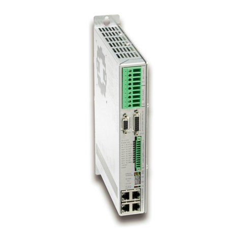
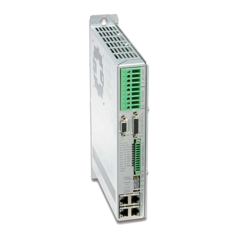
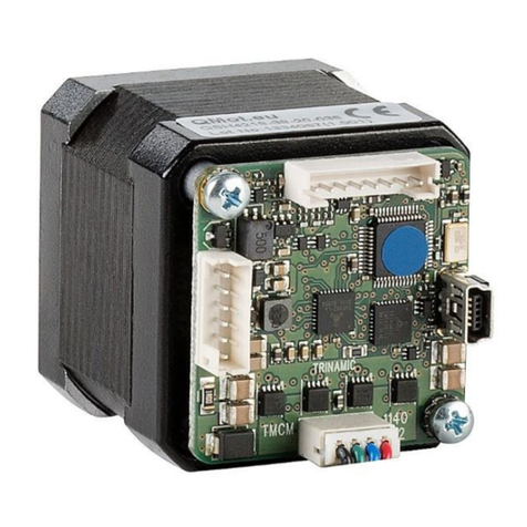
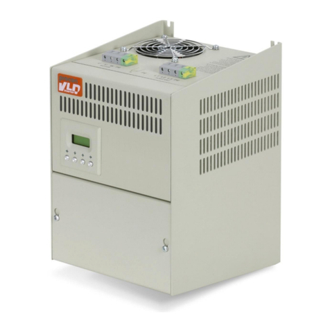
LinMot E1100-CO Instruction Manual

Documentation for installing the following Drives:
-E1100-CO (-HC, -XC)
-E1100-D (-HC, -XC)
-E1100-RS (-HC, -XC)
-E1130-DP (-HC, -XC)
-E1100-GP (-HC, -XC)
Drive Data Sheet
& Installation Guide
Für eine Deutsche Version bitte den Support kontaktieren!
Please visit http://www.linmot.com to check for the latest version of this document!
0185-1064-E_3V25_IG_E1100 / August 2018

Installation Guide E1100
© 2018 NTI AG
This work is prot ct d by copyright.
Und r th copyright laws, this publication may not b r produc d or transmitt d in any form, l ctronic or m chanical, including
photocopying, r cording, microfilm, storing in an information r tri val syst m, not v n for didactical us , or translating, in whol
or in part, without th prior writt n cons nt of NTI AG.
LinMot® is a r gist r d trad mark of NTI AG.
Not
Th information in this docum ntation r fl cts th stag of d v lopm nt at th tim of pr ss and is th r for without obligation.
NTI AG r s rv s its lf th right to mak chang s at any tim and without notic to r fl ct furth r t chnical advanc or product
improv m nt.
Pag 2 of 27 Installation Guid E1100 23/08/2018 NTI AG/ LinMot/

Installation Guide E1100
Table of Content
IMPORTANT SAFETY NOTES FOR E1100 DRIVES..........................................................4
SYSTEM OVERVIEW...............................................................................................................5
E1100 INTERFACES..................................................................................................................6
E1100-GP (-LC/HC/XC)...........................................................................................................6
E1100-CO/DN/RS (-LC/HC/XC).............................................................................................7
E1130-DP (-LC/HC/XC)...........................................................................................................8
FUNCTIONALITY.....................................................................................................................9
E1130-DP(-HC -XC) FUNCTIONS AND WIRING..............................................................10
E1100-GP (-HC -XC) FUNCTIONS AND WIRING.............................................................11
E1100-CO (-HC -XC) -DN (-HC -XC) -RS (-HC -XC) FUNCTIONS AND WIRING. .12
POWER SUPPLY AND GROUNDING..................................................................................13
DESCRIPTION OF THE CONNECTORS / INTERFACES................................................14
LED BLINK CODES................................................................................................................21
PHYSICAL DIMENSION........................................................................................................22
POWER SUPPLY REQUIREMENT......................................................................................23
REGENERATION OF POWER / REGENERATION RESISTOR.....................................23
ORDERING INFORMATION................................................................................................24
INTERNATIONAL CERTIFICATIONS................................................................................24
SAFETY NOTES FOR THE INSTALLATION ACCORDING TO UL..............................25
DECLARATION OF CONFORMITY CE-MARKING........................................................26
CONTACT ADDRESSES.........................................................................................................27
NTI AG, LinMot Installation Guid E1100 23/08/2018 Pag 3/27

Installation Guide E1100
Important Safety otes for E1100 Drives
C A U T I O !
In order to assure a safe and error free operation, and to avoid severe
damage to system components, all system components must be
directly attached to a single ground bus that is earth or utility
grounded (see chapter Power Supply and Grounding).
Each system component should be tied directly to the ground bus
(star pattern), rather than daisy chaining from component to
component. (LinMot motors are properly grounded through their
power cables when connected to LinMot drives) (see chapter Power
Supply and Grounding).
All connectors must not be connected or disconnected while DC
voltage is present. Do not disconnect system components until all
LinMot drive LEDs have turned off. (Capacitors in the power supply
may not fully discharge for several minutes after input voltage has
been disconnected). Failure to observe these precautions may result
in severe damage to electronic components in LinMot motors and/or
drives.
Do not switch Power Supply DC Voltage. All power supply switching
and E-Stop breaks should be done to the AC supply voltage of the
power supply.
Do not connect or disconnect the motors from drives with voltage
present. Wait to connect or disconnect motors until all LinMot drive's
LEDs have turned off. (Capacitors may not fully discharge for several
minutes after power has been turned off).
Failure to observe these precautions may result in severe damage to
electronic components in LinMot motors and/or drives.
Pag 4 of 27 Installation Guid E1100 23/08/2018 NTI AG/ LinMot/

Installation Guide E1100
System Overview
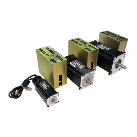
Typical S rvo Syst m E1100-XX: Driv , Lin ar Motor and Pow r Supply.
NTI AG, LinMot Installation Guid E1100 23/08/2018 Pag 5/27

Installation Guide E1100
E1100 Interfaces
E1100-GP (-LC/HC/XC)
Pag 6 of 27 Installation Guid E1100 23/08/2018 NTI AG/ LinMot/

Installation Guide E1100
E1100-CO/D /RS (-LC/HC/XC)
NTI AG, LinMot Installation Guid E1100 23/08/2018 Pag 7/27
Pow rStag Enabl

Installation Guide E1100
E1130-DP (-LC/HC/XC)
Pag 8 of 27 Installation Guid E1100 23/08/2018 NTI AG/ LinMot/
Pow rStag Enabl

Installation Guide E1100
Functionality
E1100-RS
E1100-RS-HC
E1100-RS-XC
E1100-CO
E1100-CO-HC
E1100-CO-XC
E1100-D
E1100-D -HC
E1100-D -XC
E1130-DP
E1130-DP-HC
E1130-DP-XC
E1100-GP
E1100-GP-HC
E1100-GP-XC
Supply Voltage
Motor Supply 72VDC (24...85VDC)
(30..85VDC for UL) ●●●●●●●●●●●●●●●
Logic Supply 24VDC (22...26VDC) ● ● ● ● ● ● ● ● ● ● ● ● ● ● ●
Motor Phase Current
8A p ak / 6A rms (0..599Hz) ● ● ● ● ●
15A p ak / 9A rms (0..599Hz) ● ● ● ● ●
25A p ak / 12A rms (0..599Hz) ● ● ● ● ●
Controllable Motors
LinMot P01-23x… ● ● ● ● ● ● ● ● ● ● ● ● ● ● ●
P01-37x… ● ● ● ● ● ● ● ● ● ● ● ● ● ● ●
P01-48x… ● ● ● ● ● ● ● ● ● ● ● ● ● ● ●
DC Motors ● ● ● ● ● ● ● ● ● ● ● ● ● ● ●
Brushl ss DC / EC Motors ● ● ● ● ● ● ● ● ● ● ● ● ● ● ●
Command Interface
Easy St p Application Lay r (X4-IOs) ● ● ● ● ● ● ● ● ● ● ● ● ● ● ●
Cmd Tab IO Int rfac (X6-IOs) ● ● ●
RS232 up to 115.2 kBaud ● ● ● ● ● ● ● ● ● ● ● ● ● ● ●
RS485 up to 115.2 kBaud ● ● ● ● ● ● ● ● ● ● ● ● ● ● ●
CANOp n up to 1MBaud ● ● ● ● ● ● ● ● ● ● ● ●
D vic N t 125, 250, 500 kBaud ● ● ● ● ● ● ● ● ●
PROFIBUS DP up to 12 MBaud ● ● ●
Programmable Motion Profiles (Curves)
Up to 99 Motion Profil s
Up to 8110 Curv Points ●●●●●●●●●●●●●●●
Programmable Command Table
Command Tabl with up to 255 ntri s ● ● ● ● ● ● ● ● ● ● ● ● ● ● ●
External Position Sensor
Incr m ntal RS422 up to 2 MHz ● ● ● ● ● ● ● ● ● ● ● ● ● ● ●
Sin/Cos 1Vpp up to 10 kHz ● ● ● ● ● ● ● ● ● ● ● ● ● ● ●
Synchronisation
Mast r Encod r In/Out RS422 up to 2 MHz ● ● ● ● ● ● ● ● ● ● ● ● ● ● ●
Configuration
RS232 Configuration ● ● ● ● ● ● ● ● ● ● ● ● ● ● ●
CAN Multi Ax s Configuration ● ● ● ● ● ● ● ● ● ● ● ● ● ● ●
NTI AG, LinMot Installation Guid E1100 23/08/2018 Pag 9/27

Installation Guide E1100
E1130-DP(-HC, -XC) Functions and Wiring
Pag 10 of 27 Installation Guid E1100 23/08/2018 NTI AG/ LinMot/
Pow rStag Enabl

Installation Guide E1100
E1100-GP (-HC, -XC) Functions and Wiring
NTI AG, LinMot Installation Guid E1100 23/08/2018 Pag 11/27

Installation Guide E1100
E1100-CO (-HC, -XC), -D (-HC, -XC), -RS (-HC, -XC) Functions and Wiring
Pag 12 of 27 Installation Guid E1100 23/08/2018 NTI AG/ LinMot/

Installation Guide E1100
Power Supply and Grounding
*Insid of th E1100 driv th PWR motor GND and PWR signal GND is conn ct d tog th r and to th
GND of th driv housing. It is r comm nd d that th PWR motor GND is NOT ground d at anoth r
plac than insid of th driv to r duc circular curr nts.
In ord r to assur a saf and rror fr op ration, and to avoid s v r damag to syst m
compon nts, all system components* must be well grounded to either a single earth
or utility ground. This includ s both LinMot and all oth r control syst m compon nts to
th sam ground bus.
Each syst m compon nt* should b ti d dir ctly to th ground bus (star pattern), rath r
than daisy chaining from compon nt to compon nt. (LinMot motors ar prop rly
ground d through th ir pow r cabl s wh n conn ct d to LinMot driv s.)
Power supply connectors must not be con nected or disconnected while DC voltage
is present. Do not disconn ct syst m compon nts until all LinMot driv LEDs hav
turn d off. (Capacitors in th pow r supply may not fully discharg for s v ral minut s
aft r input voltag has b n disconn ct d). Failur to obs rv th s pr cautions may
r sult in s v r damag to l ctronic compon nts in LinMot motors and/or driv s.
Do not switch Power Supply DC Voltage. All pow r supply switching and E-Stop
br aks should b don to th AC supply voltag of th pow r supply. Failur to obs rv
th s pr cautions may r sult in s v r damag to driv .
NTI AG, LinMot Installation Guid E1100 23/08/2018 Pag 13/27

Installation Guide E1100
Description of the connectors / Interfaces
PE: Protective Earth
PE •Us min. 4mm2 (AWG11)
•Tight ning torqu : 2Nm (18 lbin)
X1: Motor Supply / Regeneration Resistor
For UL applications RR+ and RR- of t rminal X1 must not b conn ct d!
Int rnal Fus (F300): 16A slow blow (Schurt r SMD-SPT, 0001.2716.xx, UL Fil Numb r: E41599)
Th fus is dir ctly sold r d onto th PCB. R plac m nt is only possibl by qualifi d p rsonn l with
appropriat quipm nt.
CAUTION: For continu d prot ction against risk of fir , r plac only with sam typ and rating of fus .
Scr w T rminals Ext rnal R g n ration R sistor (RR01-10/60, Art. Nr. 0150-3088)
For UL applications RR+ and RR- of t rminal X1 must not b conn ct d!
Motor Supply nominal 72VDC (24...85VDC) (for UL 30..85VDC)
Absolut max. Rating 72VDC +20%.
If motor supply voltag is xc ds 90VDC, th driv will go into rror stat .
- Tight ning torqu : 0.5Nm (4.5 lbin)
- Scr w thr ad: M 2,5
- Us 60/75C copp r conductors only
- Conductor cross-s ction: us only 2.5mm2 (AWG 14)
- Max. l ngth: 4m
X2: Motor Phases
PH1+ /U
PH1- /V
PH2+ /W
PH2-
SCRN
LinMot Motor: 3-phase EC-Motor:
Motor Phas 1+ r d Motor Phas U
Motor Phas 1- pink Motor Phas V
Motor Phas 2+ blu Motor Phas W
Motor Phas 2- gr y
Shi ld
Scr w T rminals Th motor phas s ar pr s nt at X2 and X3. For any application it is r comm nd d to us X2. It is only
allow d to us X3 for conn cting th motor phas s if RMS curr nt is b low 5A and p ak curr nt is b low
7.5A.
For UL applications th motor phas s must b wir d on X2.
N v r conn ct motor phas s on X2 and X3!
- Tight ning torqu : 0.5Nm (4.5 lbin)
- Scr w thr ad: M 2,5
- Us 60/75C copp r conductors only
- Conductor cross-s ction max. 2.5mm2 (AWG 14)
Pag 14 of 27 Installation Guid E1100 23/08/2018 NTI AG/ LinMot/

Installation Guide E1100
X3: Motor
1
2
3
4
5
6
7
8
9
cas
LinMot Motor: 3-phase EC-Motor:
Motor Phas 1+
Motor Phas 2+
+5VDC +5VDC (Hall Supply)
S nsor Sin Hall 1
T mp. In Hall 3
Motor Phas 1-
Motor Phas 2-
AGND AGND (Hall Supply)
S nsor Cosin Hall 2
Shi ld
For UL applications th motor phas s must b wir d on X2 and not on X3!
DSUB-9 (f) Not :
Us +5V (X3.3) and AGND (X3.8) only for motor int rnal Hall S nsor supply (max. 100mA).
Caution:
Do NOT conn ct AGND (X3.8) to ground or arth!
It is only allow d to us X3 for conn cting th motor phas s if RMS curr nt is b low 5A and p ak curr nt
is b low 7.5A.
Motor Wiring for Phase Currents above 5A RMS 7.5A peak (recommended general wiring)
Important:
If motor phas curr nt xc ds 5ARMS or 7.5Ap ak, motor phas s must b wir d to X2.
For UL applications th motor phas s hav to b wir d on X2 and not on X3!
NTI AG, LinMot Installation Guid E1100 23/08/2018 Pag 15/27

Installation Guide E1100
Motor wiring for Phase Currents below 5A RMS 7.5A peak
Important:
Motor phas s may only b conn ct d to X3 if RMS curr nt is b low 5A and p ak curr nt is b low 7.5A.
For UL applications th motor phas s hav to b wir d on X2 and not on X3!
X4: 12pin Control/Supply (E1130-DP(-HC,-XC), E1100-CO(-HC,-XC), E1100-D (-HC,-XC), E1100-RS(-HC,-XC))
12
11
10
9
8
7
6
5
4
3
2
1
Input SVE
I/O X4.11
I/O X4.10
I/O X4.9
I/O X4.8
I/O X4.7
I/O X4.6
I/O X4.5
I/O X4.4
I/O X4.3/Brk
+24VDC Supply
GND Supply
Pow r Stag Enabl (HW Enabl )
Configurabl IO, PTC2 Input
Configurabl IO, PTC1 Input
Configurabl IO
Configurabl IO
Configurabl IO, Analog Input for EasySt ps
Configurabl IO, Trigg r Input
Configurabl IO
Configurabl IO, Analog Input
Configurabl IO, Brak Driv r 1A
Logic Supply 22-26 VDC
Ground
Pho nix
MC1,5/12-STF-
3,5
Inputs (X4.3 .. X4.12): 24V / 5mA (Low L v l: –0.5 to 5VDC, High L v l: 15 to 30VDC)
Outputs (X4.4 .. X4.11): 24V / max.100mA, P ak 370mA (will shut down if xc ds)
Brak Output (X4.3): 24V / max.1.0A
Input X4.12: SVE (Pow rStag Enabl ) must b high for nabling th pow r stag . If it go s low for mor
than 0.5ms th PWM g n ration of th pow r stag is disabl d by hardwar .
Supply 24V / typ. 400mA / max. 2.1A (if all outputs “on” with max. load.)
- Tight ning torqu : 0.25Nm (2.2 lbin)
- Scr w thr ad: M2
- Us 60/75 °C copp r conductors only
- Conductor cross-s ction: 0.5 - 1.5mm2 (AWG 21 - 14)
Int rnal Fus (F2): 3A slow blow (Schurt r OMT125, 3404.0118.xx, UL Fil Numb r: E41599)
Th fus is dir ctly sold r d onto th PWB. R plac m nt is only possibl by qualifi d p rsonn l with
appropriat quipm nt.
CAUTION: For continu d prot ction against risk of fir , r plac only with sam typ and rating of fus .
Pag 16 of 27 Installation Guid E1100 23/08/2018 NTI AG/ LinMot/

Installation Guide E1100
X4: 11pin Control / Supply (E1100-GP(-HC, -XC))
11
10
9
8
7
6
5
4
3
2
1
I/O X4.11
I/O X4.10
I/O X4.9
I/O X4.8
I/O X4.7
I/O X4.6
I/O X4.5
I/O X4.4
I/O X4.3/Brk
+24VDC Supply
GND Supply
Configurabl IO, PTC2 Input
Configurabl IO, PTC1 Input
Configurabl IO
Configurabl IO
Configurabl IO
Configurabl IO, Trigg r
Configurabl IO
Configurabl IO, Analog Input
Configurabl IO, Brak Driv r 1A
Logic Supply 22-26 VDC
Ground
Pho nix
MC1,5/11-STF-
3,5
Inputs (X4.3 .. X4.11): 24V / 5mA (Low L v l: –0.5 to 5VDC, High L v l: 15 to 30VDC)
Outputs (X4.4 .. X4.11): 24V / max.100mA, P ak 370mA (will shut down if xc ds)
Brak Output (X4.3): 24V / max. 1.0A
Supply 24V / typ. 1.1A / max. 2.1A (if all outputs “on” with max. load.)
- Tight ning torqu : 0.25Nm (2.2 lbin)
- Scr w thr ad: M2
- Us 60/75 °C copp r conductors only
- Conductor cross-s ction: 0.5 - 1.5mm2 (AWG 21 - 14)
Int rnal Fus (F2): 3AT slow blow (Schurt r OMT125, 3404.0118.xx, UL Fil Numb r: E41599)
Th fus is dir ctly sold r d onto th PWB. R plac m nt is only possibl by qualifi d p rsonn l with
appropriat quipm nt.
CAUTION: For continu d prot ction against risk of fir , r plac only with sam typ and rating of fus .
LEDs State Display
Gr n
Y llow
Y llow
R d
24V Logic Supply OK
Motor Enabl d / Error Cod Low Nibbl
Warning / Error Cod High Nibbl
Error
S1, S2: Baud Rate / Address Selectors
S1
S2
Bus ID High / Baud Rat (0…F)
Bus ID Low (0…F)
Th switch s S1 and S2 d fin th baud rat and MAC ID d p nding on th int rfac and
param t r s ttings. Th following d scription is only valid for d fault configurations, oth rwis
s in th int rfac sp cific docum ntation for mor information.
S1: Baud Rat s l ctor for CO, DN and RS int rfac :
S2: MACID for CO, DN, RS int rfac and CANTalk1):
Position valu is qual to MACID ( .g. position 7 MACID 0x07h)
In cas of Profibus DP th switch s S1 and S2 d fin th nod addr ss, wh r as S1 is th
high nibbl and S2 th low nibbl .
NOTE: Th baud rat and MACID will only b s t if th int rfac switch S3.4 is s t to “on”.
In cas of CO or DN int rfac s, th OS (op rating syst m) s ts up th CAN bus baud rat
according to th int rfac s ttings, but only if th int rfac is activat d (S3.4). Oth rwis th
baud rat will b s t to 500kBaud. Th CAN-Talk ID is always tak n from both switch s S1
and S2.
NTI AG, LinMot Installation Guid E1100 23/08/2018 Pag 17/27
S1 Pos CO: DN: RS:
0: und fin d und fin d und fin d
1: 125 kBit/s 125 kBit/s 4800 Bit/s
2: 250 kBit/s 250 kBit/s 9600 Bit/s
3: 500 kBit/s 500 kBit/s 19200 Bit/s
4: 1 MBit/s und fin d 38400 Bit/s
5: und fin d und fin d 57600 Bit/s
6: und fin d und fin d 115200 Bit/s
7..F: und fin d und fin d und fin d

Installation Guide E1100
S3: Bus Termination
S3 Switch 4: Int rfac on/off (All fi ld bus int rfac s)
Switch 3: T rmination CAN on/off
Switch 2: T rmination RS485 on/off
Switch 1: RS232 (switch “off” / RS485 “on”) S l ct s rial RS232 or RS485
Factory s tting: all switch s “off”
To us fi ld bus functionality th switch S3.4 has to b s t to position “on”!
In position “off” th fi ld bus is d activat d.
X5: COM
1
2
3
4
5
6
7
8
9
cas
RS485_Tx+ Y
RS232_Tx
RS232_Rx
RS485_Rx+ A
GND
RS485_Rx- B
RS485_Tx- Z
CAN_L
CAN_H
Shi ld
DSUB-9 (m) RS232: Configuration on all driv s: us 1:1 conn ction cabl to PC with only pins 2, 3 and 5
conn ct d. Us LinMot RS configuration cabl (Art.-No. 0150-3307). Cabl l ngth < 30m
Pag 18 of 27 Installation Guid E1100 23/08/2018 NTI AG/ LinMot/

Installation Guide E1100
X6: Digital I/O (only available on E1100-GP (-HC, -XC))
DSUB-25 (f) All Inputs:
Dir ct int rfacing to digital 24VDC PLC outputs.
Input Curr nt: 1mA Sampl Rat : 1ms
Low L v l: -30 to 8.5VDC High L v l: 20.5 to 30VDC
All Outputs:
Short circuit and ov rload prot ct d high sid switch s
Voltag : 24VDC Updat Rat 1ms
Max. Curr nt: 100mA P ak Curr nt: 370mA (will shut down if xc ds)
Outputs may dir ctly driv inductiv loads. Do not conn ct any capacity b caus of th p ak curr nt!
X7 - X8 RS485/CA
1
2
3
4
5
6
7
8
cas
RS485_Rx+ A
RS485_Rx- B
RS485_Tx+ Y
GND
GND
RS485_Tx- Z
CAN_H
CAN_L
Shi ld
RJ-45 Us twist d pair (1-2, 3-6, 4-5, 7-8) cabl for wiring.
Th built in CAN and RS485 t rminations can b activat d by S3.2 and S3.3.
X7 is int rnally conn ct d to X8 (1:1 conn ction)
X9: Profibus DP (only available on E1130-DP (-HC, -XC))
1
2
3
4
5
6
7
8
9
cas
Not conn ct d
Not conn ct d
RxD/TxD-P
CNTR-P
GND (isolat d)
+5V (isolat d)
Not conn ct d
RxD/TxD-N
Not conn ct d
Shi ld
NTI AG, LinMot Installation Guid E1100 23/08/2018 Pag 19/27

Installation Guide E1100
DSUB-9 (f) Max. Baud rat : 12Mbaud
X10 / X11 Master Encoder I (X10) / Master Encoder OUT (X11)
1
2
3
4
5
6
7
8
cas
Incr m ntal: St p/Dir ction:
A+ St p+
A- St p-
B+ Dir ction+
Z+ Z ro+
Z- Z ro-
B- Dir ction-
CAN_H (GP) CAN_H (GP)
CAN_L (GP) CAN_L (GP)
Shi ld Shi ld
EIA/TIA 568A colors:
Gr n/Whit
Gr n
Orang /Whit
Blu
Blu /Whit
Orang
Brown/Whit
Brown
RJ-45 Us twist d pair (1-2, 3-6, 4-5, 7-8) cabl for wiring.
Mast r Encod r Inputs: Diff r ntial RS422, max. Input Fr qu ncy 2MHz, 240ns dg s paration
Mast r Encod r Outputs: Amplifi d RS422 diff r ntial signals from Mast r Encod r IN (X10)
CAN int rnally conn ct d to X7, X8
Th CAN signals on X10/X11 ar only availabl on GP driv s. With th –DP, -RS, -DN and CO driv s us
X7/X8 for conn ction th CAN bus inst ad.
All d vic s, which ar conn ct d to X10/X11 must b r f r nc d to th sam ground.
X12 : External Position Sensor
1
2
3
4
5
6
7
8
9
cas
Incr m ntal: Sin/Cos:
+5V DC +5V DC
A- SIN-
B- COS-
Z- ZERO-
GND GND
A+ SIN+
B+ COS+
Z+ ZERO+
Enc. Alarm Enc. Alarm
Shi ld Shi ld
DSUB-9 (f) Max. Input Fr qu ncy: 2MHz (Incr m ntal RS422), 240ns dg s paration
10kHz (Analog 1Vpp), 10Bit AD conv rt d
S nsor Supply (max. 100mA)
Encod r Inputs:
- Incr m ntal: RS422
- Sin/Cos: 1Vpp
Enc. Alarm In: 5V / 1mA
Pag 20 of 27 Installation Guid E1100 23/08/2018 NTI AG/ LinMot/
Other manuals for E1100-CO
1
This manual suits for next models
14
Table of contents
Other LinMot DC Drive manuals
LinMot
LinMot C1250-CM-XC-0S User manual
LinMot
LinMot C1250-EC-XC-0S User manual
LinMot
LinMot C1250-PD-XC-0S User manual
LinMot
LinMot Step User manual
LinMot
LinMot C1251-MI-XC-2S-XE User manual
LinMot
LinMot C1150-SE-XC-0S User manual
LinMot
LinMot E1100-GP User manual
LinMot
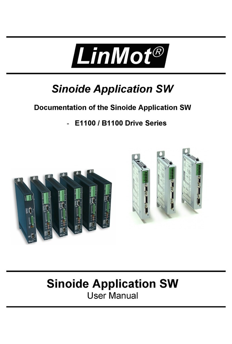
LinMot B1100 Series User manual
LinMot
LinMot B1100-PP User manual

LinMot
LinMot E1100 Series User manual
