LinMot C1250-PD-XC-0S User manual
Documentation of the PROFIdrive Interface of the following
Drives:
•C1250-PD-XC-0S/1S
•C1450-PD-VS-0S/1S
•E1450-PD-QN-0S/1S
PROFINET PROFIdrive Interface
User Manual

Page 2/38 User Manual PROFINET PROFIdrive Interface NTI AG / LinMot
© 2018 NTI AG
This work is protected by copyright.
Under the copyright laws, this publication may not be reproduced or transmitted in any form, electronic or mechanical, including
photocopying, recording, microfilm, storing in an information retrieval system, not even for didactical use, or translating, in whole
or in part, without the prior written consent of NTIAG. LinMot® is a registered trademark of NTIAG.
Note:
The information in this documentation reflects the stage of development at the time of press and is therefore without obligation.
NTI AG reserves itself the right to make changes at any time and without notice to reflect further technical advance or product
improvement.
Document version 1.3 / Whp, August 2018

NTI AG / LinMot User Manual PROFINET PROFIdrive Interface Page 3/38
1System overview............................................................................................................ 5
1.1 References.............................................................................................................. 5
1.2 Port assignement.................................................................................................... 5
2Setup in Simotion Motion Control System ...................................................................... 6
2.1 Assumed preconditions........................................................................................... 6
2.2 TIA Configuration .................................................................................................... 6
2.2.1. Create a new project........................................................................................ 6
2.2.2. Configure a Device........................................................................................... 7
2.2.3. Add new Device............................................................................................... 7
2.2.4. Select Device................................................................................................... 8
2.2.5. Configure PROFINET....................................................................................... 8
2.2.6. Install LinMot GSDML device description file.................................................... 9
2.2.7. Select correct GSDML device description file................................................... 9
2.2.8. Add NTI drive to PROFINET network..............................................................10
2.2.9. Assign NTI drive to the SIMOTION..................................................................11
2.2.10. Define the PROFINET Topology..................................................................11
2.2.11. Add communication module to the NTI PROFIdrive drive................................12
2.2.12. Define the PROFIBUS Cycle time................................................................14
2.2.13. Compile the HW Configuration ....................................................................14
2.2.14. Download the HW Configuration..................................................................15
2.3 SIMOTON SCOUT TIA Configuration.....................................................................16
2.3.1. Insert axis........................................................................................................17
2.3.2. Configure axis.................................................................................................17
2.3.3. Download SIMOTION SCOUT configuration...................................................21
2.3.4. Move the Axis with the Control panel...............................................................24
3Process Data Object (PDO) Configuration ....................................................................28
3.1 Input PDO Modules................................................................................................28
3.1.1. Standard telegram 3........................................................................................28
3.1.2. Standard telegram 5........................................................................................28
3.1.3. Standard telegram 7........................................................................................28
3.1.4. Standard telegram 9........................................................................................29
3.1.5. Siemens telegram 105 ....................................................................................29
3.1.6. Siemens telegram TDB 200 ............................................................................29
3.1.7. Real Time Config telegram 404.......................................................................29
3.1.8. Actual Position telegram 405...........................................................................29
3.1.9. Demand Position telegram 406.......................................................................29
3.1.10. WarnWord telegram 407..............................................................................29
3.1.11. ErrorCode telegram 408..................................................................................30

Page 4/38 User Manual PROFINET PROFIdrive Interface NTI AG / LinMot
3.1.12. Demand Current 32b telegram 409..............................................................30
3.1.13. Mon Channel 1 telegram 410.......................................................................30
3.1.14. Mon Channel 2 telegram 411.......................................................................30
3.1.15. Mon Channel 3 telegram 412.......................................................................30
3.1.16. Mon Channel 4 telegram 413.......................................................................30
3.1.17. Demand Current 16b telegram 414..............................................................30
3.1.18. Actual Velocity telegram 415........................................................................30
3.1.19. Demand Velocity telegram 416....................................................................31
3.2 Output PDO Modules.............................................................................................32
3.2.1. Standard telegram 3........................................................................................32
3.2.2. Standard telegram 5........................................................................................32
3.2.3. Standard telegram 7........................................................................................32
3.2.4. Standard telegram 9........................................................................................32
3.2.5. Siemens telegram 105 ....................................................................................33
3.2.6. Siemens telegram TDB 200 ............................................................................33
3.2.7. Real Time Config telegram 404.......................................................................33
4Asynchronous Configuration Protocol............................................................................34
4.1 PROFIdrive Profile Area.........................................................................................34
4.2 Manufacturer specific Profile Area..........................................................................34
4.3 Suported Services..................................................................................................34
5PROFIdrive Parameters................................................................................................35
5.1 Parameters ............................................................................................................35
5.1.1. PROFdrive/Dis-/Enable...................................................................................35
5.1.2. PROFdrive/Byte Order....................................................................................35
5.1.3. PROFdrive/Word Order...................................................................................35
5.1.4. PROFdrive/Monitoring Channels.....................................................................36
5.1.5. PROFdrive/Axis Configuration/ Axis Type........................................................36
5.1.6. PROFdrive/Axis Configuration/ Linear/Rotative Reference Velocity.................36
5.1.7. PROFdrive/Axis Configuration/ MDI Configuration ..........................................36
6Connecting to the PROFINET Network .........................................................................37
6.1 Pin Assignment of the Connectors X17-X18...........................................................37
7Contact Addresses........................................................................................................38

NTI AG / LinMot User Manual PROFINET PROFIdrive Interface Page 5/38
1 System overview
PROFINET is the open real-time Ethernet network, in this manual the PROFIdrive profile
drivs are described. The LinMot drives act as slave in this network and is implemented with
the TPS1 chip from Renesas.
For further information on the PROFINET and PROFIdrive fieldbus protocols please visit:
http://www.profibus.com/
1.1 References
All user manuals are distributed with the LinMot-Talk software the newest versions can be
downloaded from the LinMot homepage in the download section.
Ref
Title
Source
1
User Manual Motion Control SW
www.linmot.com
2
LinMot Drive Configuration over Fieldbus Interfaces SG5
www.linmot.com
1.2 Port assignement
Within the PROFINET network normally the topology is defined, for easy setup and
replacement of devices. The real time Ethernet RJ45 connector X17 is the P1 port
and the real time RJ45 connector X18 is the P2 port in this context.
PLC/ Master
X17/ P1
X18 / P2
Other Devices

Page 6/38 User Manual PROFINET PROFIdrive Interface NTI AG / LinMot
2 Setup in Simotion Motion Control System
In the following steps the integration of a LinMot PROFIdrive servo drive with a LinMot linear
motor into the SIMOTION motion controller is described. In the example a Siemens
SIMOTION D445 and a Linmot C1250-PD-XC-0S drive is used.
2.1 Assumed preconditions
The SIMOTION is in factory reset condition, the programming PC is connected over
X127/P1. The Linmot drive is completely wired, the PROFINET is wired from the SIMOTION
X150/P1 to the LinMot X17.
It is supposed, that the motor and the drive have PnP functionality, means the motor is
basically setup automatically, otherwise the mtor has to be setup manually with the LinMot-
Talk Motor-Wizard in the drive.
To achieve a good response of the master setpoint, it is important to tune also the
position controller in the LinMot-drive well!
2.2 TIA Configuration
2.2.1. Create a new project
Start the TIA Portal and create a new project BSP_10.

NTI AG / LinMot User Manual PROFINET PROFIdrive Interface Page 7/38
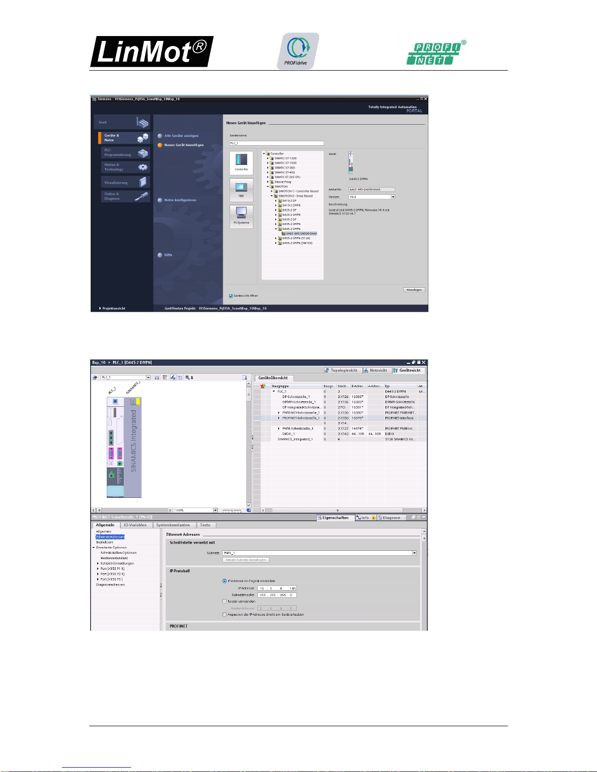
2.2.2. Configure a Device
2.2.3. Add new Device
Page 8/38 User Manual PROFINET PROFIdrive Interface NTI AG / LinMot
2.2.4. Select Device
2.2.5. Configure PROFINET
Add the PROFINET network PN/IE_1 here assigned to X150 and choose the IP-address and
subnet netmask.

NTI AG / LinMot User Manual PROFINET PROFIdrive Interface Page 9/38
Define the SIMOTION controller as Sync master in the real time settings
2.2.6. Install LinMot GSDML device description file
If not already installed, install now the newest device description file of the device you want
to use. The device description files are distributed together with the firmware under path
C:\Program Files (x86)\LinMot\LinMot-Talk 6.4 Build 20151112\Firmware\Interfaces\ProfiNet\GSDML_PD
2.2.7. Select correct GSDML device description file
Page 10/38 User Manual PROFINET PROFIdrive Interface NTI AG / LinMot
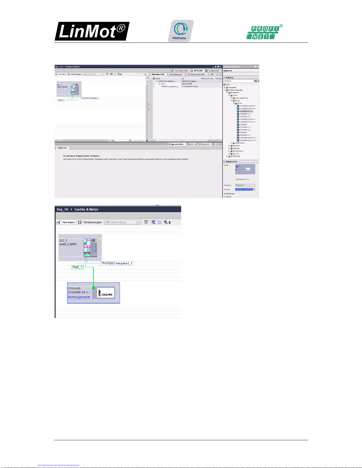
2.2.8. Add NTI drive to PROFINET network
Now change to the network view and add the desired LinMot PROFIdrive device.
Select the correct NTI drive and drag and drop it to the PN/IE1 network
Then Network looks like this.

NTI AG / LinMot User Manual PROFINET PROFIdrive Interface Page 11/38
2.2.9. Assign NTI drive to the SIMOTION
Assigne the LinMot drive to the SIMOTION master PLC_1.
Select PLC_1 as IO Controller
2.2.10. Define the PROFINET Topology
Change to Topology view, and wire the PROFINET connection from PLC-1 X150/P1 port to
the C1250-PD/P1 port.

Page 12/38 User Manual PROFINET PROFIdrive Interface NTI AG / LinMot
2.2.11. Add communication module to the NTI PROFIdrive drive
Double click in the Topology view the LinMot drive, then automatically the device view of the
LinMot drive opens.
Drag and drop from the Catalog the DO with standard telegr. 5 to the device Slot 1. Double
click the device and define the isochronous mode.

NTI AG / LinMot User Manual PROFINET PROFIdrive Interface Page 13/38
Double click thethe Slot 1.2 and assign the I/O address to the Servo Process image.
Page 14/38 User Manual PROFINET PROFIdrive Interface NTI AG / LinMot
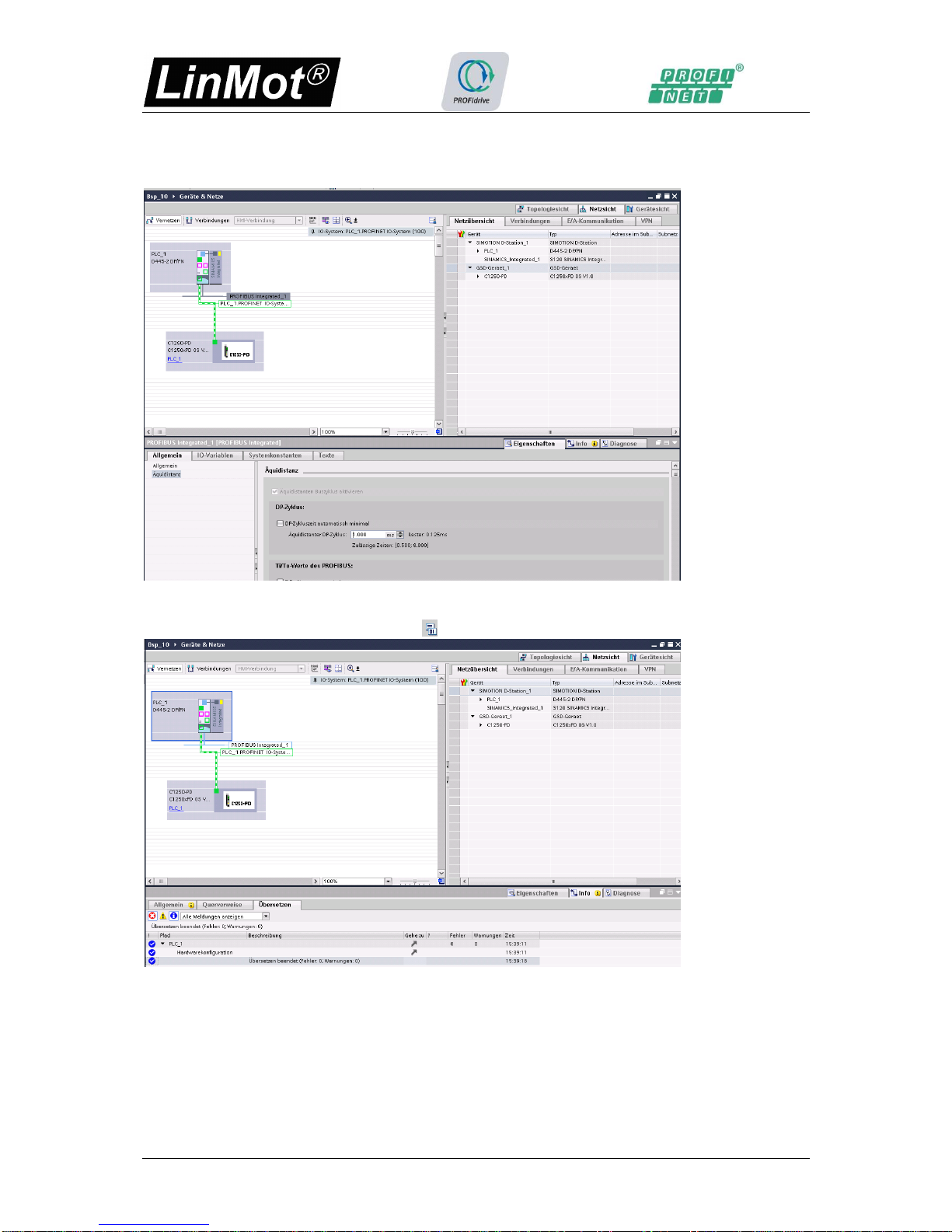
2.2.12. Define the PROFIBUS Cycle time
For the SIMOTION D devices the DP cycle time has to be the same as the Isochronous
PROFINET IO cycle time, so change it to 1ms.
2.2.13. Compile the HW Configuration
Select the SIMOTION device and click Compile button for compiling the HW configuration.
NTI AG / LinMot User Manual PROFINET PROFIdrive Interface Page 15/38
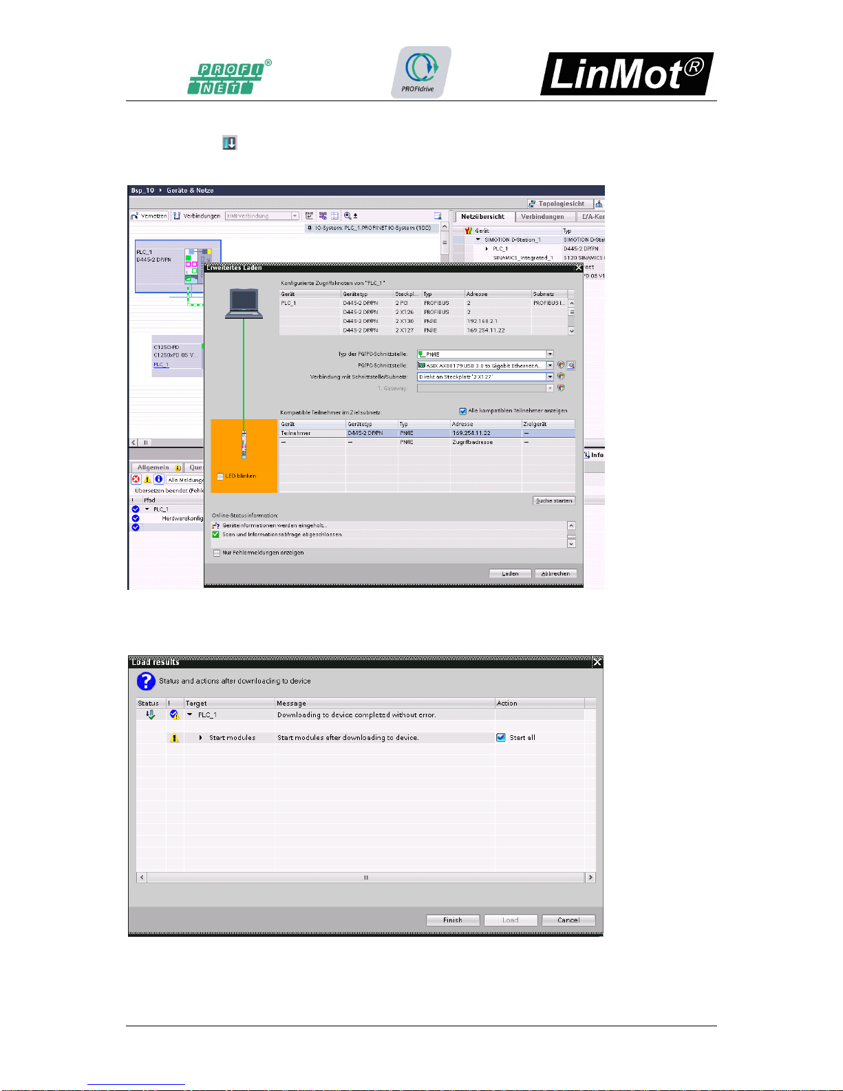
2.2.14. Download the HW Configuration
By clicking the button you start the download of the HW configuration. Select your HW
devices for accessing the SIMOTION master, click search, then select the SIMOTION device
and start the loading by clicking on the “Load” button.
After successful download you get ask for starting the devices select “Start all” check box
and click the “Finish” button.

Page 16/38 User Manual PROFINET PROFIdrive Interface NTI AG / LinMot
2.3 SIMOTON SCOUT TIA Configuration
Now change to the configuration in the SIMOTION SCOUT configuration tool by double
cklicking the “SIMOTION configuration” in the Project tree
Then the SIMOTION SCOUT TIA tool opens with the configured HW PLC_1 [D445-2DP/PN]
and C1250-PD drive

NTI AG / LinMot User Manual PROFINET PROFIdrive Interface Page 17/38
2.3.1. Insert axis
Open the Axes and double click on the “Insert Axis” entry.
2.3.2. Configure axis
The axis type could be left as suggested, click the next button.

Page 18/38 User Manual PROFINET PROFIdrive Interface NTI AG / LinMot
The drive assignment is also correct mapped to the C1250-PD drive, but change the motor
type to Linear motor, then click Next>.
In the Encoder assignement change the ??? to linear, then click Next>.
NTI AG / LinMot User Manual PROFINET PROFIdrive Interface Page 19/38
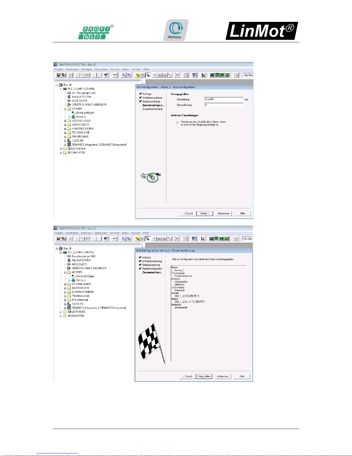
Change the resolution to 1e-004mm because the NTI drives works with a fix resolution of
100nm. Then Click next>.
Now a summary of the configured axis appears. Click Finished.

Page 20/38 User Manual PROFINET PROFIdrive Interface NTI AG / LinMot
To avoid axis errors due too high encoder frequencies the parameter
“encoderFrequencylimit” has to be increased in the “expert list” Tab “Configuration data”
Entry: TypeOfAxis/NumberOfEncoders/Encoder_1/FrequencyLimit/encoderFrequencyLimit to
100’000’000. With this value a theoretical maximal velocity of 10m/s is possible, due the
encoder resolution of 100nm.
This manual suits for next models
5
Table of contents
Other LinMot DC Drive manuals

LinMot
LinMot C1251-MI-XC-2S-XE User manual

LinMot
LinMot B1100 Series User manual

LinMot
LinMot Step User manual

LinMot
LinMot E1250-LU-UC User manual

LinMot
LinMot E1130-DP-HC User manual

LinMot
LinMot B1100-PP User manual

LinMot
LinMot E1100-GP User manual

LinMot
LinMot E1100 Series User manual

LinMot
LinMot C1250-EC-XC-0S User manual

LinMot
LinMot C1150-SE-XC-0S User manual


