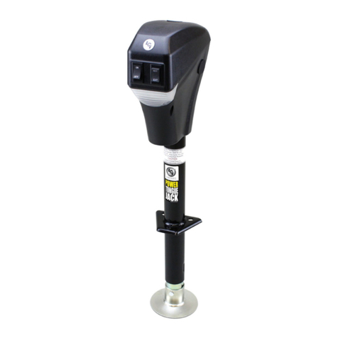
Lippert Components Power Stance User manual

Power Stance™
Tongue Jack
OWNER'S MANUAL

Rev: 12.02.20 Page 2 CCD-0003430
TABLE OF CONTENTS
Introduction 2
Safety 3
Operation 4
Unhitching From Tow Vehicle 4
Hitching to Tow Vehicle 5
Power Swap Auxiliary Cord - Optional 5
Manual Operation 6
Troubleshooting 7
Fuse 7
Clutch 7
Introduction
The Power Stance™ tongue jack is used with travel trailer A-frame applications. The textured casing helps
protect from chips and cracks. Three LED lights provide excellent illumination while reducing power
consumption. Helical cut gears reduce noise and improve operating efficiency. Enhanced rocker switch
improves its durability. The Power Stance tongue jack is protected by an in-line fuse and has an18” stroke
with a 3,500-lb capacity. A chain holder under the jack head provides a place to store chains when they are
not attached to the tow vehicle.
NOTE: The Power Stance tongue jack is designed for vertical movement of the trailer only.
NOTE: Images used in this document are for reference only when assembling, installing and/or operating
this product. Actual appearance of provided and/or purchased parts and assemblies may differ.
Additional information about this product can be obtained from lci1.com/support or by using the myLCI
app. Replacement kits can be ordered from https://store.lci1.com/ or by using the myLCI app.
The myLCI app is free on iTunes® for iPhone® and iPad® and also on Google Play™ for Android™ users.
iTunes®, iPhone®, and iPad® are registered trademarks of Apple Inc.
Google Play™ and Android™ are trademarks of Google Inc.
For information on the assembly or individual components of this product, please visit:
https://support.lci1.com/leveling-and-stabilization-support-tongue-jacks .

Rev: 12.02.20 Page 3 CCD-0003430
The "WARNING" symbol above is a sign that a procedure has a safety risk involved and may cause death or
serious personal injury if not performed safely and within the parameters set forth in this manual.
Failure to follow instructions provided in this manual may result in death, serious personal injury
and/or severe product and property damage, including voiding of the component warranty.
Moving parts can pinch, crush, or cut. Keep clear at all times.
The “CAUTION” symbol above is a sign that a safety risk is involved and may cause personal injury
and/or product or property damage if not safely adhered to and within the parameters set forth
in this manual.
Failure to retract all jacks prior to travel may result in severe product and trailer damage, including
serious personal injury or death to people and pets. Make sure all jacks are retracted prior to travel.
The trailer must be supported per manufacturer's recommendations before working underneath.
Failure to do so may result in death or serious personal injury.
All electrical wiring harnesses shall be loomed and secured to prevent possible damage and
installed in accordance with RVIA electrical standards.
Safety
Read and understand all instructions before installing or operating this product. Adhere to all safety labels.
This manual provides general instructions. Many variables can change the circumstances of the instructions,
i.e., the degree of difficulty, operation and ability of the individual performing the instructions. This
manual cannot begin to plot out instructions for every possibility, but provides the general instructions,
as necessary, for effectively interfacing with the device, product or system. Failure to correctly follow the
provided instructions may result in death, serious personal injury, severe product and/or property damage,
including voiding of the LCI limited warranty.

Rev: 12.02.20 Page 4 CCD-0003430
Fig. 1
Operation
NOTE: The Power Stance power tongue jack can be operated by utilizing either a battery stored in the
trailer, or by drawing power from the tow vehicle using the optional Power Swap Auxiliary Cord™.
NOTE: When RET (Fig. 2A) or EXT (Fig. 2B) on the switch is pushed, the light above the switch (Fig. 3A) will
turn on automatically, and remain on for five minutes. It will then automatically turn off.
NOTE: The Power Stance tongue jack is designed for vertical movement of the trailer only.
Unhitching From Tow Vehicle
1. Chock the tires of the trailer.
2. Make sure the footpad of the Power Stance power tongue jack is pinned securely in place with the
clevis pin and hairpin cotter pin (Fig. 1A).
A
3. Make sure the ground surface under the Power Stance tongue jack is firm and level.
4. Push EXT (Fig. 2B) to extend the Power Stance tongue jack until the footpad touches the ground and
the coupler clears the hitch ball.
NOTE: When RET (Fig. 2A) or EXT (Fig. 2B) is pushed, the light above the switch (Fig. 3A) will turn on
automatically, and remain on for five minutes. It will then automatically turn off.
5. Disconnect all electrical and mechanical connections between the trailer and tow vehicle.
NOTE: Chains can be stored on the chain holder (Fig. 2D) when not in use.
6. Move the tow vehicle away from the trailer.
7. Push RET (Fig. 2A) as needed to return the front of the trailer to level.
Fig. 2 Fig. 3
A
A
B
C
D

Rev: 12.02.20 Page 5 CCD-0003430
Hitching to Tow Vehicle
1. Chock the tires of the trailer.
2. Press EXT (Fig. 2B) if needed to allow the coupler to clear the hitch ball.
3. Position the tow vehicle under the trailer's hitch.
4. Push RET (Fig. 2A) to retract the Power Stance tongue jack until the coupler properly mounts the hitch
ball and the leg of the Power Stance tongue jack is fully retracted.
5. Reconnect all electrical and mechanical connections between the trailer and tow vehicle.
6. Make sure the leg of the Power Stance tongue jack is fully retracted and tire chocks are removed prior
to moving the tow vehicle.
Power Swap Auxiliary Cord - Optional
The Power Swap Auxiliary Cord (Fig. 4) allows the user to power the Power Stance tongue jack from the
battery of the tow vehicle when there is no battery power from the trailer.
NOTE: The Power Swap Auxiliary Cord is optional and sold separately.
All electrical wiring harnesses shall be loomed and secured to prevent possible damage and
installed in accordance with RVIA electrical standards.
Fig. 4
A
B
1. Insert the 7-way plug (Fig. 4A) into the 7-way connector on the tow vehicle.
2. Insert the 2-pin connector (Fig. 4B) into the plug receptacle of the Power Stance tongue jack (Fig. 2C).

Rev: 12.02.20 Page 6 CCD-0003430
Manual Operation
NOTE: In the event of loss of power, the Power Stance tongue jack can be operated manually.
1. Manually unhitching from tow vehicle:
A. Chock the tires of the trailer.
B. Be sure the footpad of the Power Stance tongue jack is pinned securely in place with the clevis pin
and hairpin cotter pin (Fig. 5B).
C. Make sure the ground surface under the power tongue jack is firm and level.
Fig. 5
A
B
D. Open the rubber plug (Fig. 6A) on top of the Power Stance tongue jack's gearbox to expose the
manual drive shaft.
Fig. 6
A
E. Insert the socket end of the manual crank handle (Fig. 7A) into the manual drive shaft.
Fig. 7
A

Rev: 12.02.20 Page 7 CCD-0003430
F. Turn the manual crank handle (Fig. 7) clockwise until trailer is supported and the coupler clears the
hitch ball.
G. Move the tow vehicle away from the trailer.
H. Lower the trailer until it is level by turning the manual crank handle counterclockwise.
I. Remove the manual crank handle (Fig. 7).
J. Replace the rubber plug (Fig. 6A).
2. Manually reconnecting to tow vehicle:
A. Chock the tires of the trailer.
B. Make sure the footpad of the Power Stance tongue jack is pinned securely in place with the clevis
pin and hairpin cotter pin (Fig. 5B).
C. Open the rubber plug (Fig. 6B) on top of the Power Stance tongue jack’s gearbox to expose the
manual drive shaft.
D. Insert the socket end of the manual crank handle (Fig. 7A) into the manual drive shaft.
E. Turn the manual crank handle clockwise to allow the coupler to clear the hitch ball.
F. Position the tow vehicle under the trailer hitch.
G. Turn the manual crank handle counterclockwise until the coupler properly mounts the hitch ball.
Continue to turn the manual crank handle counterclockwise until the leg of the Power Stance
tongue jack (Fig. 5A) is fully retracted.
H. Remove the manual crank handle (Fig. 7).
I. Replace the rubber plug (Fig. 6A).
J. Make sure tire chocks are removed prior to moving the tow vehicle.
Troubleshooting
Fuse
The Power Stance tongue jack is provided with a 30A ATO-type in-line fuse which will need to be replaced if
it blows. The battery must be fully charged prior to operating the Power Stance tongue jack.
Low voltage from the battery will cause the fuse to blow prematurely.
NOTE: When RET or EXT on the switch is pushed, the light above the switch (Fig. 3A) will turn on
automatically, and remain on for five minutes. It will then automatically turn off.
Clutch
The Power Stance tongue jack is provided with a clutch and a motor. The clutch will slip under two conditions:
A. The Power Stance tongue jack has reached its extend or retract limit.
B. The tongue weight of the trailer has exceeded the capacity limits of the Power Stance tongue
jack. Items stored in the trailer can vastly influence the weight on the Power Stance tongue jack.
Reorganize stored items if the Power Stance tongue jack motor clutch continues to slip.
Release the switch immediately when clutch noise occurs. The clutch is the overload protection for the
motor. The clutch should not slip during normal operation. Slipping will cause excessive wear to the clutch
and motor.

The contents of this manual are proprietary and copyright protected by Lippert Components, Inc. (LCI).
LCI prohibits the copying or dissemination of portions of this manual unless prior written consent from an
authorized LCI representative has been provided. Any unauthorized use shall void any applicable warranty.
The information contained in this manual is subject to change without notice and at the sole discretion of LCI.
Revised editions are available for free download from lci1.com.
Please recycle all obsolete materials.
For all concerns or questions, please contact
Lippert Components, Inc.
Table of contents
Other Lippert Components Jack manuals

Lippert Components
Lippert Components Stabilizer Jack User manual
Lippert Components
Lippert Components Level-Up 5th Wheel User manual

Lippert Components
Lippert Components Atwood RV Power Jack Owner's manual
Lippert Components
Lippert Components 285318 Installation instructions

Lippert Components
Lippert Components LCI User manual

Lippert Components
Lippert Components Standalone Smart Jack Manual
Lippert Components
Lippert Components Smart Jack 643589 Installation instructions

Lippert Components
Lippert Components 285318 Manual
Lippert Components
Lippert Components JT's Strong Arm 191023 Installation instructions


