CURTMFG.COM •PRODUCT SUPPORT: 877.287.8634 •16574-INS-RC •08/30/2022 •ECN9936 •PAGE 1
Product Registration and Warranty
CURT stands behind our products with
industry-leading warranties. To get copies
of the product warranties, register your
purchase or provide feedback, visit:
warranty.curtgroup.com/surveys
Weight Carrying Capacity
Gross trailer weight (GTW) 25,000 lbs.
Vertical load 6,250 lbs.
INSTALLATION MANUAL 16574
Tools Required
Torque wrench Socket set
Level of Difficulty
Easy
Installation difficulty levels are based on time
and effort involved and may vary depending on
the installer level of expertise, condition of the
vehicle and proper tools and equipment.
NOTICE
Visit www.curtmfg.com for a full-color copy of this
instruction manual, as well as helpful videos, guides and much more!
Before you begin installation, read all instructions thoroughly.
Proper tools will improve the quality of installation and reduce the time required.
Periodic inspection of your product should be performed
to ensure all hardware and / or components remain secure.
To help prevent damage to the product or vehicle, refer to the specified
torque specifications when securing hardware during the installation process.
WARNING
Never exceed the vehicle manufacturer's recommended towing capacity. Trailer and
contents combined must not exceed tow vehicle, hitch and / or trailer tow ratings.
Exceeding rated capacity may result in separation. Exceeding rated capacity may result
in damage to 5th wheel hitch, towing vehicle, trailer and / or cause serious injury or death.
Fully instruct and demonstrate the operation of this 5th wheel slider to the end user. Include
the importance of observing all warnings contained herein. Provide this manual in its entirety
to the end user. Serious injury or death may result if all warnings are not observed.
To avoid serious injury, do not expose hands, body parts or clothing between
the truck and trailer or the truck's bed sides and trailer. Extreme care should
be observed to avoid serious injury to self, property and observers.
Improperly coupled trailers can separate and drop without notice. Never position
yourself or others under the trailer's kingpin area (danger zone) during coupling and
uncoupling. If for any reason you must position any part of your body under the trailer,
between the truck and the trailer or between the trailer's kingpin and 5th wheel hitch,
you must follow the steps in the 'Danger Zone Precautions' section above.
Parts List*
Item Qty Description
1 1 Slider assembly
2 4 Rail pin
3 4 Rail clip
4 4 Rubber spacer
5 2 Pin plate
6 4
Replacement 5th wheel head bolts
* 5th wheel base rails are required
for installation (sold separately)
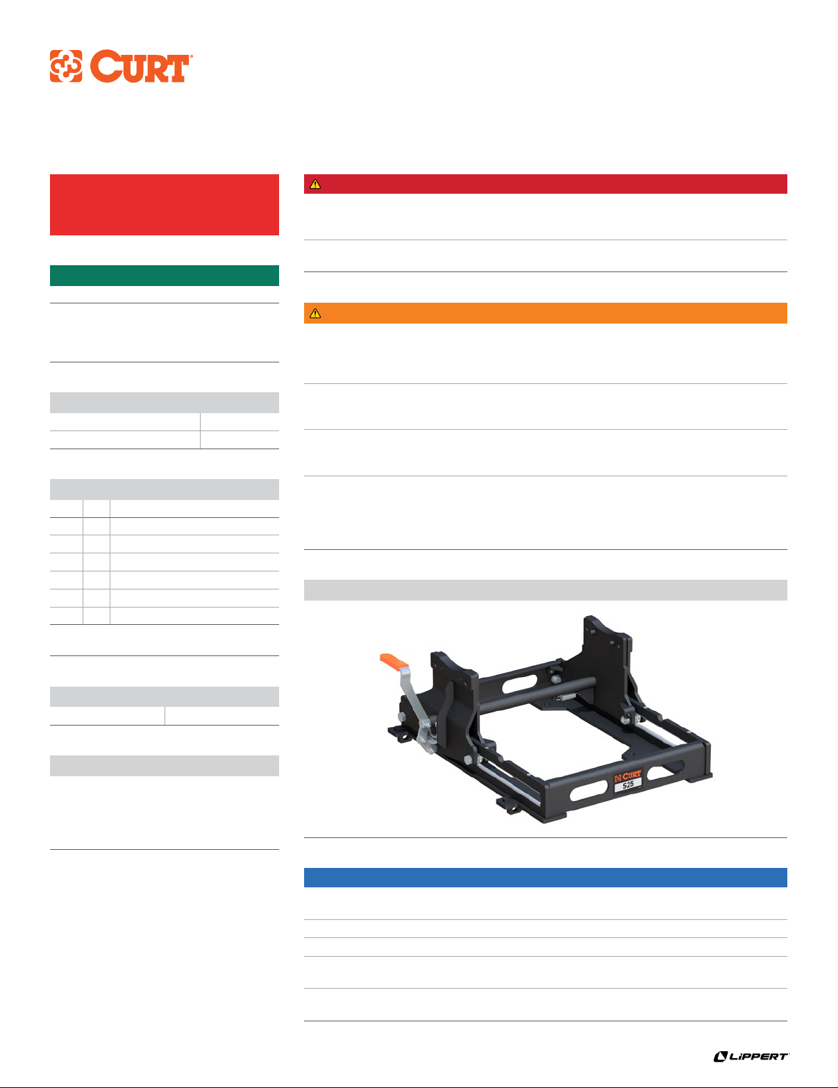
Product Photo
This is the first of two manuals
required to complete this installation.
The second manual is included with
your 5th wheel head.
DANGER ZONE PRECAUTIONS
Block all trailer tires in front and behind with appropriate wheel chocks. Do not
substitute objects such as, but not limited to: stones, wood blocks, etc. Front trailer
lifting jacks must be supporting the trailer and resting on a firm and level surface.
Towing vehicle must be stationary with automatic transmission
in park (manual in neutral), emergency brake applied and engine off.


