2
lippert.com 432-LIPPERT (432-547-7378) Rev: 08.29.22
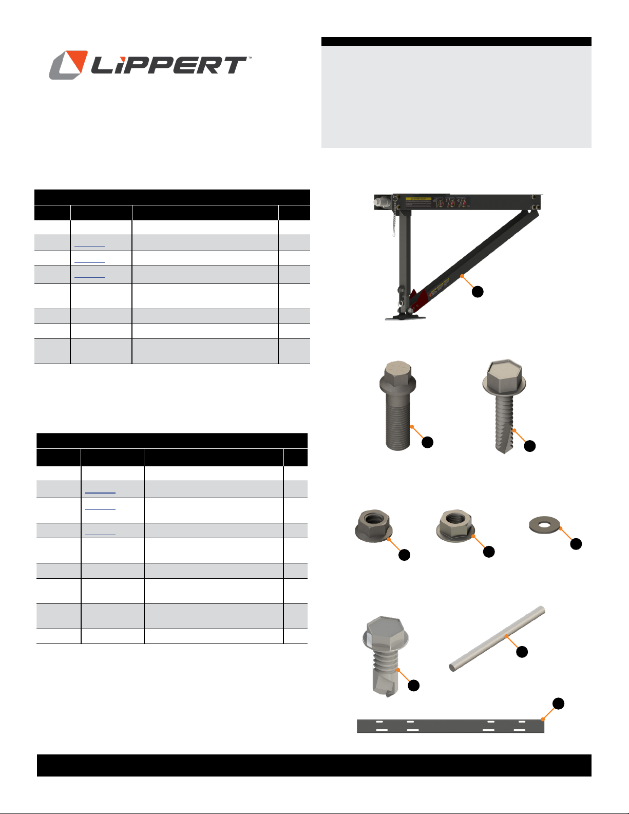
Quick Drop Stabilizer
Installation and Owner’s Manual
(For Aftermarket Applications)
CCD-0004455
Introduction
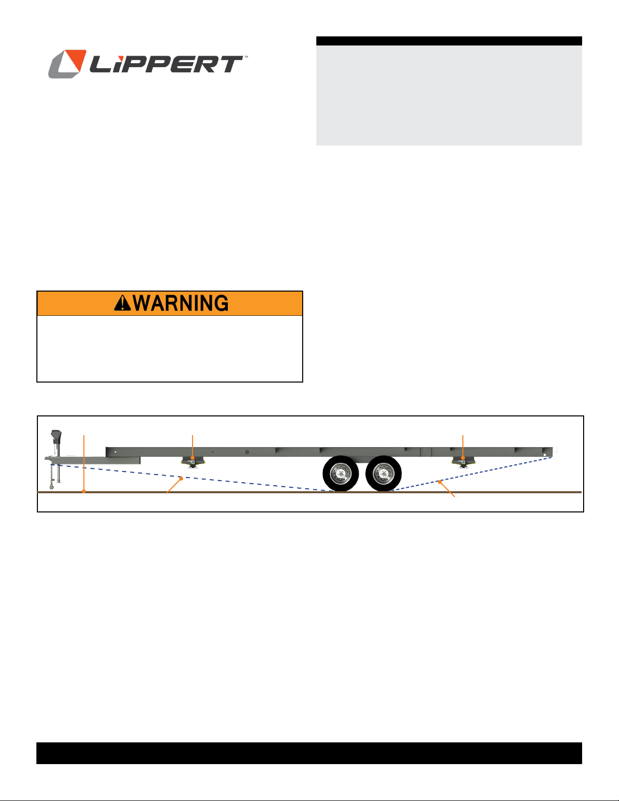
Quick Drop Stabilizers can be installed on travel trailers
and 5th wheels. Travel trailer options include both front and
rear stabilizers or a rear stabilizer only, while 5th wheels
typically utilize only a rear stabilizer.
Additional information about this product can be obtained
from lci1.com/support or by downloading the free
LippertNOW. The app is available on Apple App Store®for
iPhone®and iPad®and also on Google Play™for Android™
users.
iPhone®, and iPad®are registered trademarks of Apple Inc.
Google Play™and Android™are trademarks of Google Inc.
Safety
Read and understand all instructions before installing or
operating this product. Adhere to all safety labels.
This manual provides general instructions. Many variables
can change the circumstances of the instructions, i.e., the
degree of difficulty, operation and ability of the individual
performing the instructions. This manual cannot begin
to plot out instructions for every possibility, but provides
the general instructions, as necessary, for effectively
interfacing with the device, product or system. Failure
to correctly follow the provided instructions may result
in death, serious personal injury, severe product and/
or property damage, including voiding of the LCI limited
warranty.
Quick Drop Stabilizers are intended for the purpose of
stabilizing the trailer after the trailer has been leveled. The
use of this system for any reason other than which it is
intended is prohibited by Lippert’s Limited Warranty and
may result in serious personal injury or death. Quick Drop
Stabilizers are designed as a stabilizing component system
and should not be used to provide service for any reason
under the trailer such as changing tires or repairing or
replacing any components beneath the trailer.
THE “WARNING” SYMBOL ABOVE IS A SIGN THAT
AN INSTALLATION PROCEDURE HAS A SAFETY
RISK INVOLVED AND MAY CAUSE DEATH, SERIOUS
PERSONAL INJURY OR SEVERE PRODUCT OR
PROPERTY DAMAGE IF NOT PERFORMED SAFELY
AND WITHIN THE PARAMETERS SET FORTH IN THIS
MANUAL.
QUICK DROP STABILIZERS ARE DESIGNED AS
A STABILIZING COMPONENT ONLY. DO NOT USE
ANY QUICK DROP STABILIZERS TO LEVEL A
TRAILER. USE OF QUICK DROP STABILIZERS TO
LIFT A TRAILER FOR SERVICE CAN CREATE A
DANGEROUS SITUATION THAT CAN RESULT IN
DEATH, SERIOUS PERSONAL INJURY OR SEVERE
PRODUCT OR PROPERTY DAMAGE.
MOVING PARTS CAN PINCH, CRUSH OR CUT. KEEP
CLEAR AND USE CAUTION.