8
lippert.com 432-LIPPERT (432-547-7378) Rev:06.30.22
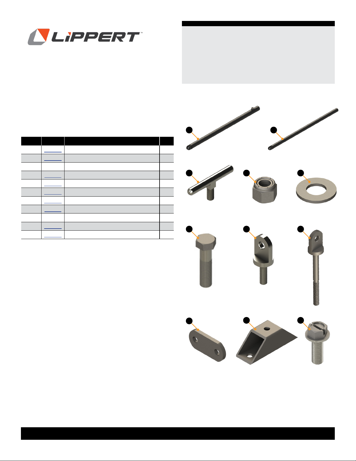
JT’s Strong Arm™
Travel Trailer
Installation and Owner’s Manual
(For Aftermarket Applications)
CCD-002345
9.
10.
11.
the top side of the stabilizers.
12.
⁄
⁄
and a ⁄
step on the opposite side.
13.
⁄
⁄⁄
NOTE:
14.
Steps 8-10. Repeat for opposite side.
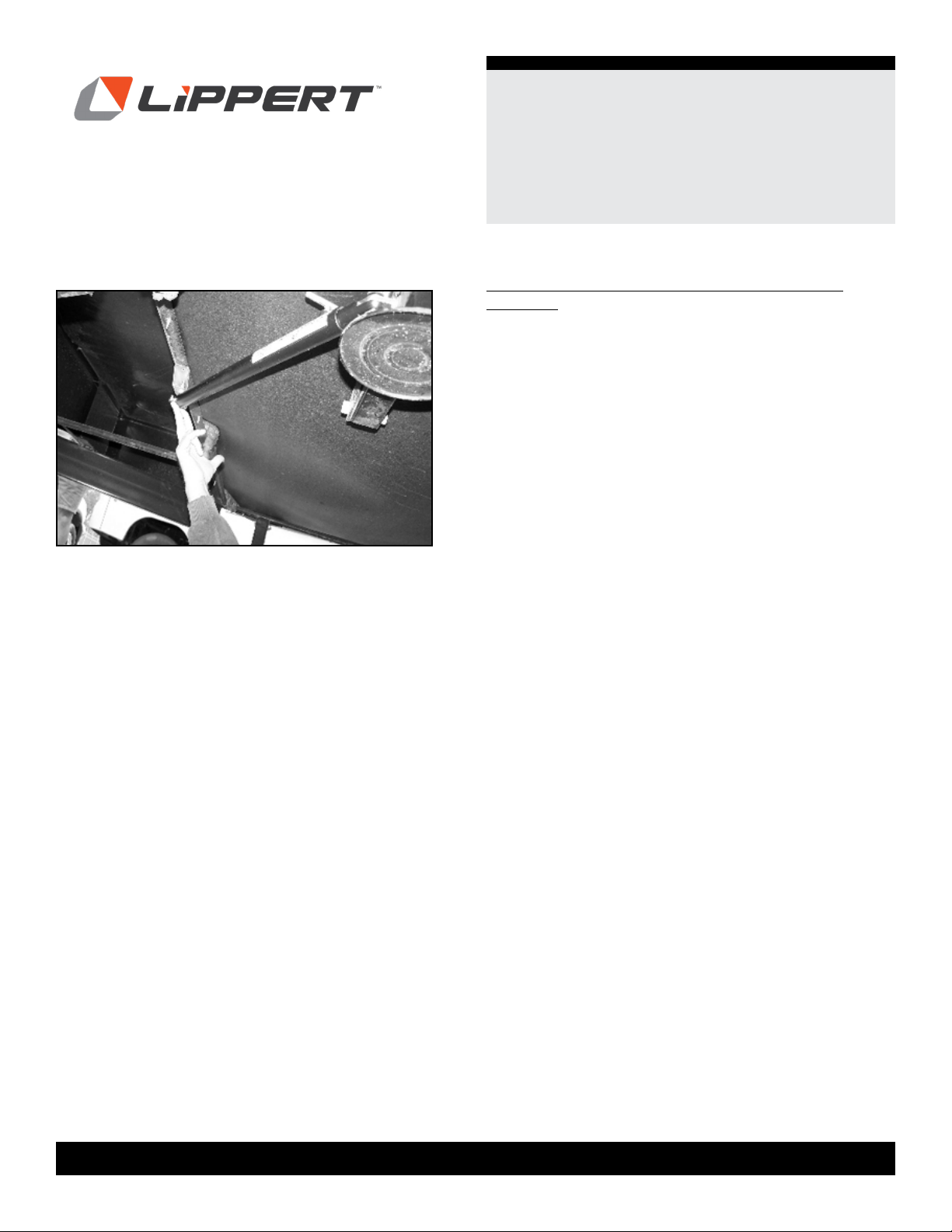
15.
⁄⁄
⁄
(Fig.11). Repeat this step on the
opposite side.
Chassis Specific Instructions: C-Channel
1. Attach a ⁄
⁄⁄
2.
3.
4.
of the cross-member front-to-back on the bottom of the
cross-member.
5.
6.
⁄
bit.
7. ⁄
⁄⁄
Fig.11