Rev: 01.04.22 Page 9 CCD-0004321
A
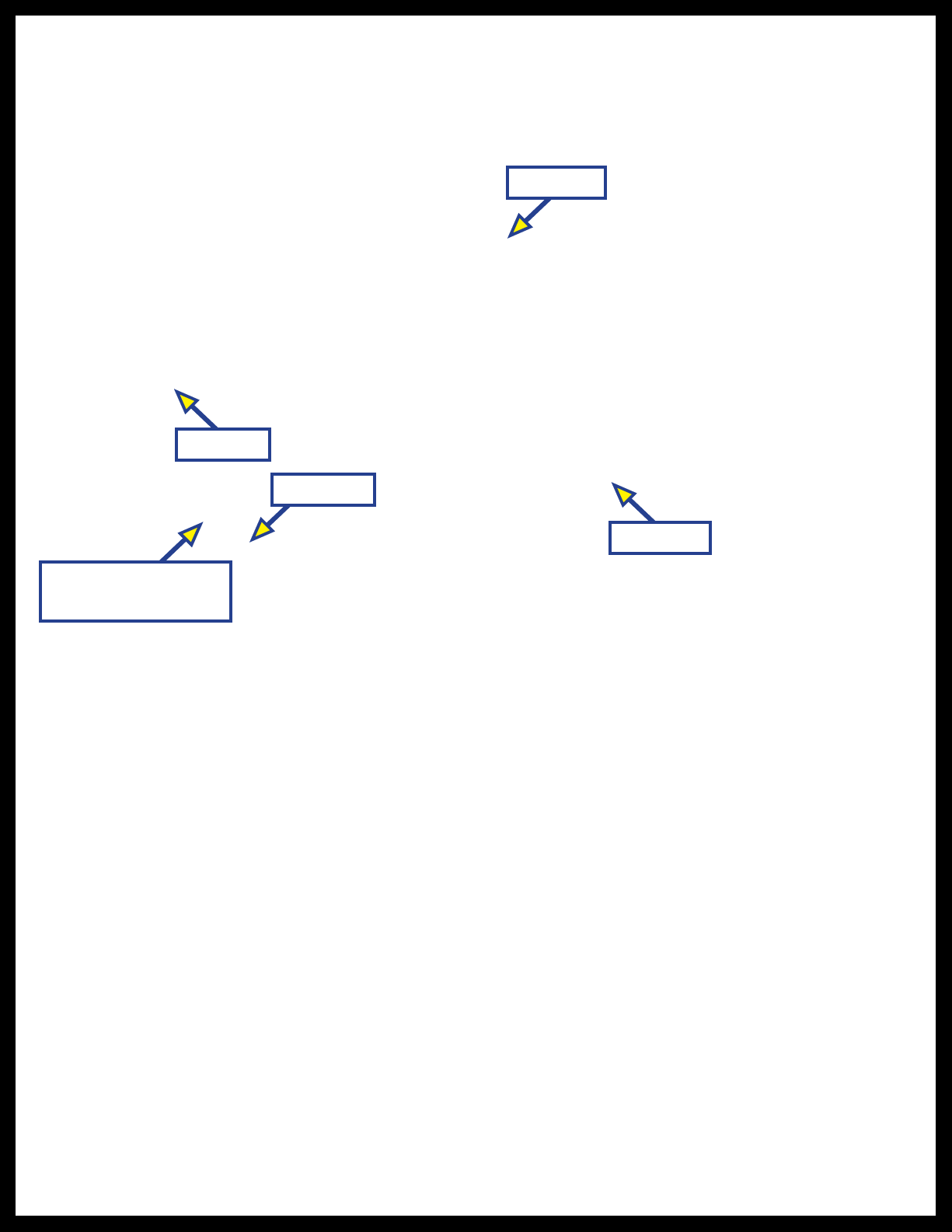
Fig. 6
E. Pull downward on each tie-down's adjustment buckle (Fig. 6A) until the fly extension is taut and
does not sag.
If the power bimini is equipped with the Lippert high speed mesh top, the fly extension can also be reversed
and passed underneath the top to provide rain and additional sun protection. The reversed use of the fly
extension is secured to the rear rails with the same stanchions and tie-down straps used at the front.
Do NOT exceed 15 mph when y extension is deployed. Exceeding maximum speed limit with y
extension deployed can cause damage to the extension and void product warranty.
The maximum 15 mph speed limit MUST still be observed when the fly extension is deployed in the
reversed position. Even when deployed in the reverse position, exceeding the maximum speed limit can
cause damage to the extension.
If the fly extension is stored, follow the same procedure to deploy it as outlined for securing it to the front of
the boat (previous steps 1 and 2) except walk the extension towards rear of the boat.
If the fly extension is already deployed to the front of the boat, deploy it to the rear of theboat as follows:
1. Use adjustment buckles to loosen tie-down straps, then unclip them from their saddles.
2. Slide the locking button on the locking plates back, then lift the stanchion pole out of the
lockingplate.
3. Grasp the stanchions and walk the fly extension towards the rear of the boat, under the top.
4. Insert each stanchion in its respective locking plate.
5. Extend and clip each stanchion's tie-down strap onto its saddle.
6. Use adjustment buckles to pull tie-down straps until the fly extension is taut and does not sag.
To store the fly extension, do as follows:
1. Loosen tie-down straps and unclip them from their saddles.
2. Remove the stanchions from their locking plates.
3. Place the stanchions and tie-down straps onto the fly extension material.
4. Roll the stanchions and straps up into the fly extension material towards the front storage pocket of
the top.
5. Tuck the rolled up material into the storage pocket.
6. Zip the storage pocket closed.
Bimini Speakers
Use of the protective boot, fly extension or position of the bimini top will not affect speaker performance.
1. Turn on electrical power to the boat.
2. Turn on and operate the boat's entertainment system.
3. Use the entertainment system's controls to adjust speaker balance, tone and volume.