Lithionics Battery 12V130A-G31-LRBM8 User manual

MiniBMS
12V130A-G31-LRBM8 User Guide
RB
®
TECHNOLOGY
®
NeverDie® Compact Series 100 Internal BMS
Part Number: 74-505

Notice of Copyright
12V130A-G31-LRBM8 User Guide Copyright © 2021 all rights reserved. No part of this document may be reproduced in any form
without the express consent of Lithionics Battery, Clearwater, FL 33765 USA. Lithionics Battery reserves the right to revise this
document and make periodic changes to the contents without obligation or organization of such changes and revisions.
Index
Index.................................................................................................................................................................................................2
Safety................................................................................................................................................................................................2
Overview..........................................................................................................................................................................................2
Battery Installation.....................................................................................................................................................................3
First Power-up...............................................................................................................................................................................4
Operation ........................................................................................................................................................................................4
Battery Charging ..........................................................................................................................................................................5
Power Button with Status Light.............................................................................................................................................6
Maintenance and Storage.........................................................................................................................................................6
Bluetooth App................................................................................................................................................................................7
BMS Functions...............................................................................................................................................................................9
Battery Specifications ..............................................................................................................................................................10
Troubleshooting & FAQ............................................................................................................................................................11
Contact Information .................................................................................................................................................................11
Safety
▪All electrical work should be performed in accordance with local and national electrical codes.
▪Assume that voltage is present at the battery terminals, use insulated tools and gloves while working on the system.
▪Always turn off equipment connected to the battery in addition to turning OFF the Power switch on the battery to isolate it from
other electrical circuits, before performing any repairs or maintenance on the system.
▪Always use proper wire sizes to connect the system to inverters, chargers or other equipment.
▪Always use crimped connections to connect to the battery terminals.
▪Read and follow the inverter, charger or other equipment manufacturers safety precautions prior to connecting the battery to
that equipment.
▪Always use charging equipment compatible with Lithium Iron Phosphate battery chemistry. See battery charging section below.
Overview
The 12V130A-G31-LRBM8 battery is a lithium-ion iron phosphate (LiFePO4) chemistry battery with an internal Battery Management
System (BMS) technology called NeverDie® Compact BMS. The BMS monitors voltage, current and temperature of the cells inside the
battery and protects the battery from potential damage by disconnecting the battery circuit when the monitored parameters go
outside of the allowed limits. The BMS also transmits monitoring data over the integrated Bluetooth interface, allowing customers to
check the battery data on their mobile phones or tablets.

LITHIONICS BATTERY, CLEARWATER, FL 33765 USA
PH: 727.726.4204 | FAX: 727.797.8046 | WEB: LITHIONICSBATTERY.COM
Page 3of 11
Battery Installation
Before installation, check the battery for visible damage including cracks, dents, deformation and other visible abnormalities. The top
surface of the battery and terminal connections should be clean, free of dirt and corrosion, and dry.
Battery power should be turned off prior to the installation and for storage. Check the LED integrated into the Power button to make
sure it is completely off. If the LED is on or blinking, press and hold the Power button for 3 seconds until LED turns off.
Lithium batteries do not release gas during normal use. There are no specific ventilation requirements for battery installation, although
enough airflow should be provided to prevent excessive heat build-up.
The battery should be stored and installed in a clean, cool and dry place, keeping water, oil, and dirt away from the battery. If any of
these materials can accumulate on the top surface of the battery, current leakage can occur, resulting in self-discharge and possible
short circuits.
The orientation of the battery must be with the terminals
facing up as shown. Sideways, and upside-down
orientations are not permitted and will void the warranty.
The battery is equipped with two flat threaded terminals designed for a 5/16” or M8 size ring terminal lugs secured by the included
M8 bolts, flat washers and lock washers. When using flat washers and lock washers, it is critical to place the ring terminal lug in direct
contact with the top surface of the power terminal first and then place the washers on top of the lug. Connect the positive and negative
battery cables with correct polarity and double check the polarity of battery circuit to avoid potential equipment and battery damage.
CAUTION: Do NOT place any washers between the
battery power terminal and the ring terminal lug, as this
could create a high resistance path and cause excessive
heating of the connection which could then lead to
permanent battery damage and/or fire.
If you must attach more than one lug to each terminal,
ensure that at least 1/4” or 6mm of bolt thread is available
to secure the connection. Additionally, the ring terminal
lugs need to be “clocked” in such a way that they do not
interfere with their flat conducting surfaces. Acquire and
use longer M8x1.25mm stainless bolts as necessary.
Tighten both M8 power terminal bolts to 108in-lbs/12.2Nm to ensure there is good contact with the ring terminal lug.
CAUTION: Over-tightening the terminal bolts can damage the terminal. Loose terminal bolts can result in a high resistance
connection which could then lead to permanent battery damage and/or fire.
For parallel battery connecting, the use of bus
bars or diagonal take-off points is required.
CAUTION: Improper terminal connection or
lug stacking may cause battery damage that
is not covered under warranty.

LITHIONICS BATTERY, CLEARWATER, FL 33765 USA
PH: 727.726.4204 | FAX: 727.797.8046 | WEB: LITHIONICSBATTERY.COM
Page 4of 11
The battery cables should be sized to handle the expected load. Refer to NEC Table 310.15(B)16 for the maximum amperage based on
the cable gauge size. Cable lengths more than 6 feet may require heavier gauge wire to avoid unacceptable voltage drop. When
connecting multiple batteries in parallel to make larger battery banks, it is preferable for all parallel cables to be the same length.
For more information refer to the National Electrical Code for correct cable size, which can be located at www.nfpa.org
The battery circuit must be properly fused to handle the expected load and not to exceed the battery specifications.
After installation is complete, turn on the battery power by a short-press of the Power button. The LED indicator will illuminate to
confirm the battery’s powered on state.
DO NOT connect multiple batteries in series to get higher voltage as it will damage the internal BMS.
DO NOT attempt to disassemble the battery, as it could lead to permanent battery damage and will void your battery warranty.
First Power-up
The battery needs to be fully charged to 14.4V to condition the battery for use. Fully charging the battery calibrates the state-of-charge
percentage to be the most accurate and allows the cells to balance if necessary. The battery should be fully charged to 14.4V at least
once every 2 weeks.
Operation
Before powering on, ensure the battery terminals are insulated and any connected devices are properly fused.
Due to shipping laws and regulations, your battery may be received at a partial state-of-charge (typically 50%). The battery needs to
be fully charged before use. This is necessary to calibrate the state-of-charge meter.
Powering the Battery On The power button is located on the battery lid and/or on the remote accessory harness extension. To turn
the battery on, press the power button for one second. The power button status light will illuminate solid on to confirm the battery is
powered on and operating normally.
Powering the Battery Off Be sure to shut down any high amperage loads prior to turning the battery off. To turn the battery off,
press and hold the power button for 3 seconds. The power button status light will turn off to confirm that battery power is off.
Resetting Power after a Protection Event If the battery detects a fault then it may turn power off. The battery can then be reset by
pressing the power button for one second.
Discharging Discharging may be performed at any time the system is powered On. The NeverDie® feature allows the system to
have a “reserve” amount of energy left in the battery. Once the system is discharged to approximately 12.0V or 10% state-of-charge,
whichever comes first, power will be off to leave a “reserve” amount of energy still left in the battery. The battery will also disconnect
power if the voltage, amperage, or temperature limits are exceeded during discharging. To enable the remaining reserve energy of
the system, press the BMS power button for 1 second. Once the reserve range is enabled the battery should be charged as soon as
possible. See page 9 BMS Functions for further details.
WARNING - If the reserve energy is used and the battery module is left in a deeply discharged state without immediate charging, the
battery module may become permanently damaged.

LITHIONICS BATTERY, CLEARWATER, FL 33765 USA
PH: 727.726.4204 | FAX: 727.797.8046 | WEB: LITHIONICSBATTERY.COM
Page 5of 11
Battery Charging
The charging device(s) connected to the Lithium Battery System must be programmed per the recommended charge settings below.
Using an improper charger or charge settings could result in undesirable battery performance and accelerated wear. The battery will
disconnect power if the voltage, amperage, or temperature limits are exceeded during charging. Please note that voltage rise during
bulk charge stage is very slow, followed by a fast voltage rise at the end of charge. Once charge is completed, the voltage drops down
to a resting level. This behavior is normal and should not cause any concerns.
A lithium iron phosphate (described as LFP or LiFePO4) charger or
charging profile is required for battery charging. The battery
charge voltage should be set to 14.4V, equalization and
temperature compensation must be disabled, and if the charger
supports float mode, set it to 13.4 - 13.6V. If you are not sure if
your charger is suitable for charging your battery, contact
Lithionics Battery® or your dealer to confirm charger
compatibility, or to purchase compatible charger.
NOTE: Due to partial state-of-charge during storage and
shipping, the cells inside the battery may not be perfectly
balanced during the first few charge cycles. You may observe
some high voltage alerts and cell balancing status codes on
the Lithionics Battery® Monitor app, which indicate the
balancing process is in progress. This is perfectly normal
behavior and should not cause any concerns. After a few full
charge cycles the cells will balance out and these alerts will
disappear. There is no adverse effect on battery operation,
you may continue to use the battery normally during these
initial charge cycles.
Screen shots on the left show examples of status
codes related to cell balancing.
Recommended Charge Settings
Recommended Bulk Charging Voltage
14.4V
Recommended Absorb Charging Voltage
14.4V
Recommended Absorb Cycle Time
30 Minutes
Maximum Absorb Cycle Time
60 Minutes
Recommend Float Voltage
13.4V
Maximum Float Voltage
13.6V
Equalization Mode
Disabled
Temperature Compensation
Disabled

LITHIONICS BATTERY, CLEARWATER, FL 33765 USA
PH: 727.726.4204 | FAX: 727.797.8046 | WEB: LITHIONICSBATTERY.COM
Page 6of 11
Power Button with Status Light
The BMS power button is located on the battery lid and includes a status light. You can also attach
the optional remote power button (Lithionics Part # 75-224-196) via the panel mount connector. This
can be useful if the battery is installed in a location that is not easily accessible. The function and
operation of the remote power button remains the same as the main power button on the battery.
Refer to the table below for an explanation of the power button status light blink patterns.
Battery State Status Light
Powered On Solid ON
Powered Off Solid OFF
Charging Slow blink
Low Battery Short blink
Fault Alarm Rapid blink
Status Light pattern over time
< 1 second >
< 1 second >
< 1 second >
< 1 second >
Maintenance and Storage
Maintenance For optimal performance when in use, the battery should be fully charged to 14.4V at least once every 2 weeks.
Fully charging the battery calibrates the state-of-charge percentage to be the most accurate and allows the cells to balance if
necessary.
Storage Storing your battery at the correct specifications is important as it keeps the battery in the healthiest state possible.
Consult the table below for proper storage conditions.
Storage Temperature & Humidity Range
< 1 Month
-4~95°F (-20~35°C), 45~75%RH
< 3 Months
14~86°F (-10~30°C), 45~75%RH
Long Term Storage
If the battery needs to be stored for > 3 months the voltage should be 13.2V
(50% state-of-charge) and stored at the recommended storage specifications
shown above. Additionally, the battery needs at least one charge & discharge
cycle every six months.
Self-Discharge Rate
≤3% per month
Typical storage example < 1 month:
1. Fully charge the battery.
2. Turn the battery OFF using the battery power button.
3. Keep the battery in an environment according to the specifications shown above.
Typical storage example > 1 month, up to 6 months maximum:
1. Reduce the battery state-of-charge to 13.2V which is 50% ±10% state-of-charge.
2. Turn the battery OFF via the BMS power button.
3. Keep the battery in an environment according to the specifications shown above.
4. Every 6 months charge the battery to 100% state-of-charge, then discharge the battery to LVC, then charge it back to 50% ±10%
state-of-charge.
Power Button Operation
Power ON
Press for 1 Second
Power OFF
Press for 3 Seconds
Power Reset
Press for 1 Second (after protection event)

LITHIONICS BATTERY, CLEARWATER, FL 33765 USA
PH: 727.726.4204 | FAX: 727.797.8046 | WEB: LITHIONICSBATTERY.COM
Page 7of 11
Bluetooth App
Lithionics Battery® has developed the Lithionics Battery® Monitor app for iOS and Android mobile platforms, which allows
real time battery information. The battery must be turned on via the Power button before the Bluetooth connection can be made.
When the battery is turned off, Bluetooth is also powered off to save energy. This app can be downloaded for free on the Apple App
Store or the Google Play Store for your iOS 12.4+ or Android 5.0+ device.
To connect Bluetooth:
1) The battery must be in the ON position.
2) Bluetooth must be enabled on your device.
3) Open the Lithionics Battery® Monitor App and accept location permissions.
4) Under the Device List, select the battery you would like to monitor (the device name is
identified by the battery serial number).
Once the Bluetooth connection is made to the battery, the Battery Info section of the
app automatically displays. This section provides useful info such as the battery state-of-
charge percentage, voltage, current, power, internal cell temperature, BMS temperature,
power state and estimated time remaining. Clicking on the Status Code at the bottom
automatically opens the Status Code reader section.
The Status Code Reader section of the app makes it easy to visualize the status by
observing the color-coded table, see example to the left.
Each active description is color coded in green or red, where green indicates information
and red indicates faults or critical conditions requiring attention, such as immediate need
to charge the battery.

LITHIONICS BATTERY, CLEARWATER, FL 33765 USA
PH: 727.726.4204 | FAX: 727.797.8046 | WEB: LITHIONICSBATTERY.COM
Page 8of 11
The Bluetooth app can also be used to access the Firmware
Update section of the app. The BMS firmware version and
update status can be found in the settings menu when
connected to the Battery.
NOTE - The firmware update should only be performed if
necessary.
Additionally, the app provides automatic data logging
when connected to the battery. The log files can be found
under the settings menu and can be easily shared from the
app for troubleshooting or analyzing battery history.

LITHIONICS BATTERY, CLEARWATER, FL 33765 USA
PH: 727.726.4204 | FAX: 727.797.8046 | WEB: LITHIONICSBATTERY.COM
Page 9of 11
BMS Functions
Below is a detailed description of advanced BMS features and how they affect the state of the battery. Some features depend on setup
parameters which are described in detail in the Configuration section of this user guide.
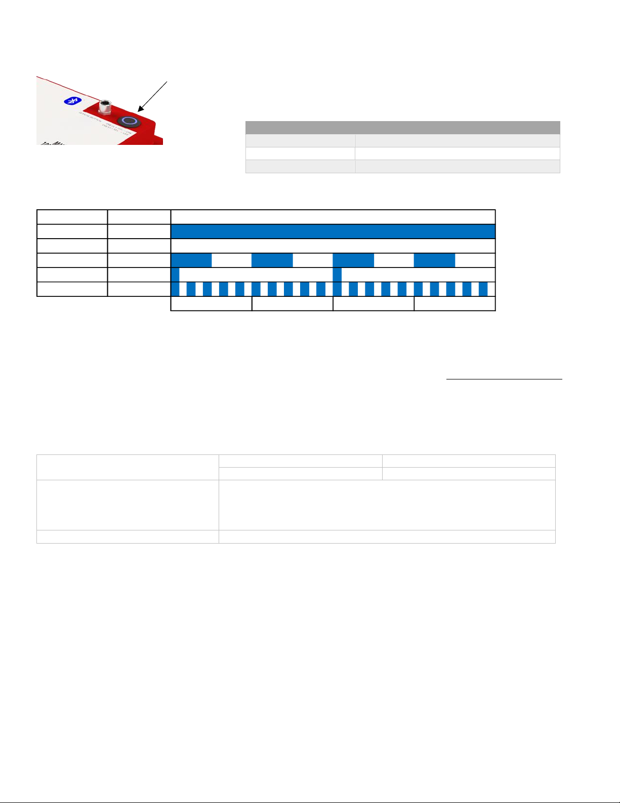
▪Power On/Off –In addition to the automatic disconnect protections, the battery can be manually turned off to disconnect
power at the terminals during installation, service, or storage.
▪Reserve Voltage Cutoff (RVC) –During discharge, the BMS will disable discharge current at approximately 10% state-
of-charge, or when any cell reaches 3.0V (approximately 12.0V total voltage). This allows the battery to store a small energy
reserve. Once the battery is in the RVC state you can use the reserve energy by a short-press of the power button.
oIt is recommended to charge the battery soon once it reaches RVC.
oThe battery will fully power off if it is not charged after sitting for 72 hours to further conserve its energy.
▪Low Voltage Cutoff (LVC) –During discharge, the BMS will disable discharge current when any cell reaches the 2.6V
(approximately 10.4V total voltage). Charging current is allowed, so that the battery can still be charged by a charging source.
Some charging sources require to “see” the battery voltage before allowing charging, in which case LVC lockout can be
temporarily overridden by short-pressing the Power button. This will allow the charger to sense the battery voltage, so
charging can begin.
oIt is recommended to charge the battery immediately once it reaches LVC.
oThe battery will fully power off if it is not charged after sitting 12 hours to further conserve its energy.
▪High Voltage Cutoff (HVC) –During charging, the BMS will disable charge current if any cell reaches 3.75V or higher
(approximately 14.8V total voltage). This should not happen during normal operation if the charging sources are setup with
correct charge settings. Once the charge current is removed the battery voltage will slowly lower and the BMS will
automatically disengage HVC.
▪Cell Temperature Based Cutoff –When the internal battery temperature goes below or above the temperature limits
the BMS will disable charge or discharge current to prevent further use of the battery until the temperature returns to safe
operating limits. Different temperature limits are enforced for charging and discharging due to the nature of LiFePO4
chemistry. Please see the specifications table below for temperature limits.
▪BMS Temperature Based Cutoff –When the BMS temperature goes above 180F the BMS will disable charge and
discharge current to prevent further use of the battery until the temperature lowers to below 160F.
▪Over Current Protection –The BMS will disable discharge or charge current if the amperage exceeds 125A for 2 minutes
continuously. To restore normal operation, remove/address the source of the overload, then short-press the Power Button.
▪Short Circuit Protection –The BMS will immediately disable discharge current if the current value exceeds 1200A. To
restore normal operation, remove/address the source of the short circuit, then short-press the Power Button.
NOTE - The lithium battery is capable of significant power output and may maintain the voltage level during a short circuit
event, producing a very large current capable of melting or welding connection points and damaging cables and connectors.
Even when the BMS detects the short circuit and tries to protect, the BMS may be damaged under such a large current. Make
sure that the battery connection is always properly fused and does not rely on the BMS alone for short circuit protection!

LITHIONICS BATTERY, CLEARWATER, FL 33765 USA
PH: 727.726.4204 | FAX: 727.797.8046 | WEB: LITHIONICSBATTERY.COM
Page 10 of 11
Battery Specifications
Item
Description
Model
12V130A-G31-LRBM8
Nominal Voltage
12.8V
Nominal Capacity
130Ah
Internal Resistance
≤4mΩ
Features
NeverDie® Reserve, High and Low Voltage Cutoff,
High and Low Temperature Cutoff, Short Circuit
Protection, Bluetooth App Support, Remote Reset
Port
NOTE: Battery may not be connected in series to make 24 volts or higher.
Charge
Charging temperature range
32~113°F (0~45°C)
Charge voltage
14.4±0.1V
Recommended float charge voltage (for standby
use)
13.5±0.1V
Recommended charge current
≤50A
Allowed max charge current
100A with starting temp of 77°F (25°C)
Discharge
Discharging temperature range
-4~131°F (-20~55°C)
Output Voltage Range
10.4~14.6V
Recommended discharge current
≤80A
Max continuous discharge current
100A with starting temp of 77°F (25°C)
Surge discharge current
<400A for 30s max with starting temp of 77°F (25°C)
Pulse discharge current
<1000A for 1s max with starting temp of 77°F (25°C)
Reserve cut-off voltage
12.0V±0.05V
Discharge cut-off voltage
10.4±0.1V
Mechanical Characteristics
Dimensions
Length 12.5in (318mm)
Width 6.5in (165mm)
Height 8.46in (215mm)
Weight
Approx. 33.4lbs (15.1Kg)
Storage
Storage Temperature &
Humidity Range
< 1 Month
-4~95°F (-20~35°C), 45~75%RH
< 3 Months
14~86°F (-10~30°C), 45~75%RH
Recommended
storage
59~95°F (15~35°C),45%RH~75%RH
Long Term Storage
If the battery needs to be stored for > 3 months the voltage should be 13.2V
(50%SoC) and stored at the recommended storage specifications shown
above. Additionally, the battery needs at least one charge & discharge cycle
every six months.
Self-discharge rate
Residual capacity
≤3% per month; ≤15% per year
Reversible capacity
≤1.5%per month; ≤8% per year

LITHIONICS BATTERY, CLEARWATER, FL 33765 USA
PH: 727.726.4204 | FAX: 727.797.8046 | WEB: LITHIONICSBATTERY.COM
Page 11 of 11
Troubleshooting & FAQ
When troubleshooting your battery, one of the most helpful tools is the battery Status Code feature of the Lithionics Battery Monitor
App. If the battery shuts down due to a protective BMS feature, please have the Bluetooth app available when resetting the battery
to identify the battery info and status code. It can be helpful to screenshot the battery info screen, which will identify the battery
state-of-charge, voltage, current, temperature, and status code. The following status code descriptions can be used in correcting the
battery fault condition.
Frequently Asked Questions
1. The battery has been charging for a long time, why has it not reached 100%?
Depending on the charger output, charging could take several hours to complete. To confirm the battery is charging, check
the Bluetooth app to verify positive current is going into the battery. The voltage rise during bulk charge stage is very slow,
followed by a fast voltage rise at the end of charge to 14.4V. Once the battery reaches 14.4V, the State-of-Charge percentage
will calibrate to 100%. If no current is measured, confirm the charger is powered on, programmed correctly, and there are no
Fuses, DC breakers or disconnect switches preventing power from transferring.
2. The battery is at 100%, why is it still charging?
It is normal for the charger to finish the charging cycle for a short period of time after the State-of-Charge percentage
calibrates to 100%. A 30-60 minute absorb cycle is recommended as the battery finishes charging and the charging current
reduced. The charger should then switch to a float charging mode at the battery resting voltage.
3. I have lost battery power, why did the battery turn off?
The battery has many automatic protections that could cause the battery to turn off. Most commonly, the battery will turn
off once you reach the 10% reserve range and just needs to be recharged. Using the Bluetooth app and Status Code can
provide you with helpful information for troubleshooting.
4. Why is the battery status light flashing?
The LED flash pattern can indicate if the battery is being charged, in a low voltage state, or experiencing a fault condition.
Reference the chart on page 6 for the status light pattern descriptions.
Contact Information
For technical or warranty support please first contact the dealer where the system was purchased.
Additionally, for factory support please send an email with your battery’s serial number to Support@LithionicsBattery.com
Description of Status Codes in the Lithionics Battery Monitor App
High Voltage State
The battery’s voltage is too high, typically 14.8V (3.75V per cell).
Cell Temp High/Low
The battery’s internal temperature is outside of the operating limits.
NeverDie® Reserve
The battery is in the NeverDie® Reserve State, allowing access to reserve energy.
BMS Temp High
The temperature of the BMS is too high, typically due to high charge or discharge current.
Reserve Range
The battery’s voltage is low (below 12.0V and/or 10%) and should be charged soon.
Low Voltage State
The battery’s voltage is very low (below 10.4V) and should be charged immediately.
Battery Overload
The charge or discharge current is over 125A and power will be turned off after 2 minutes.
Power Off State
The battery was turned off by the Power Button.
Overcurrent State
The discharge current has exceeded 600A, and power is now turned off.
Short Circuit Protection
The discharge current has exceeded 1200A, and power is now turned off.
Cell Over-Voltage
One of the battery’s cell voltages is too high. Charge current to the battery is disabled.
Cell Under-Voltage
One of the battery’s cell voltages is too low. Discharge current from the battery is disabled.
BMS fault
A BMS fault is present.
Cell 1 Balancing
Cell 1 is balancing.
Cell 2 Balancing
Cell 2 is balancing.
Cell 3 Balancing
Cell 3 is balancing.
Cell 4 Balancing
Cell 4 is balancing.
This manual suits for next models
1
Table of contents
Other Lithionics Battery Batteries Pack manuals