12V 12V
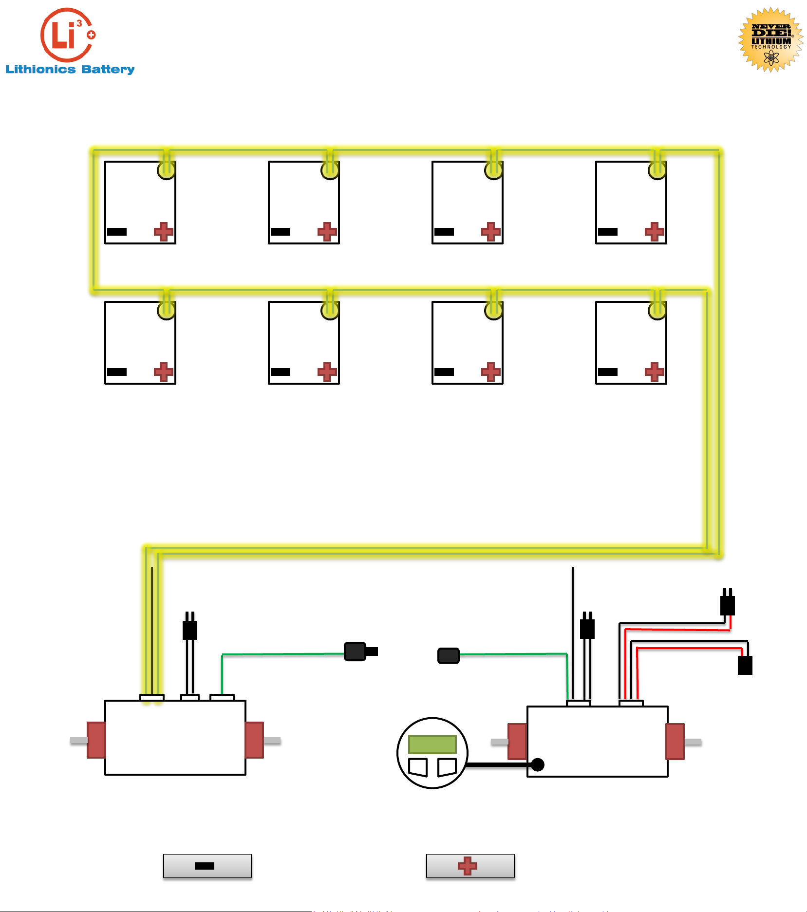
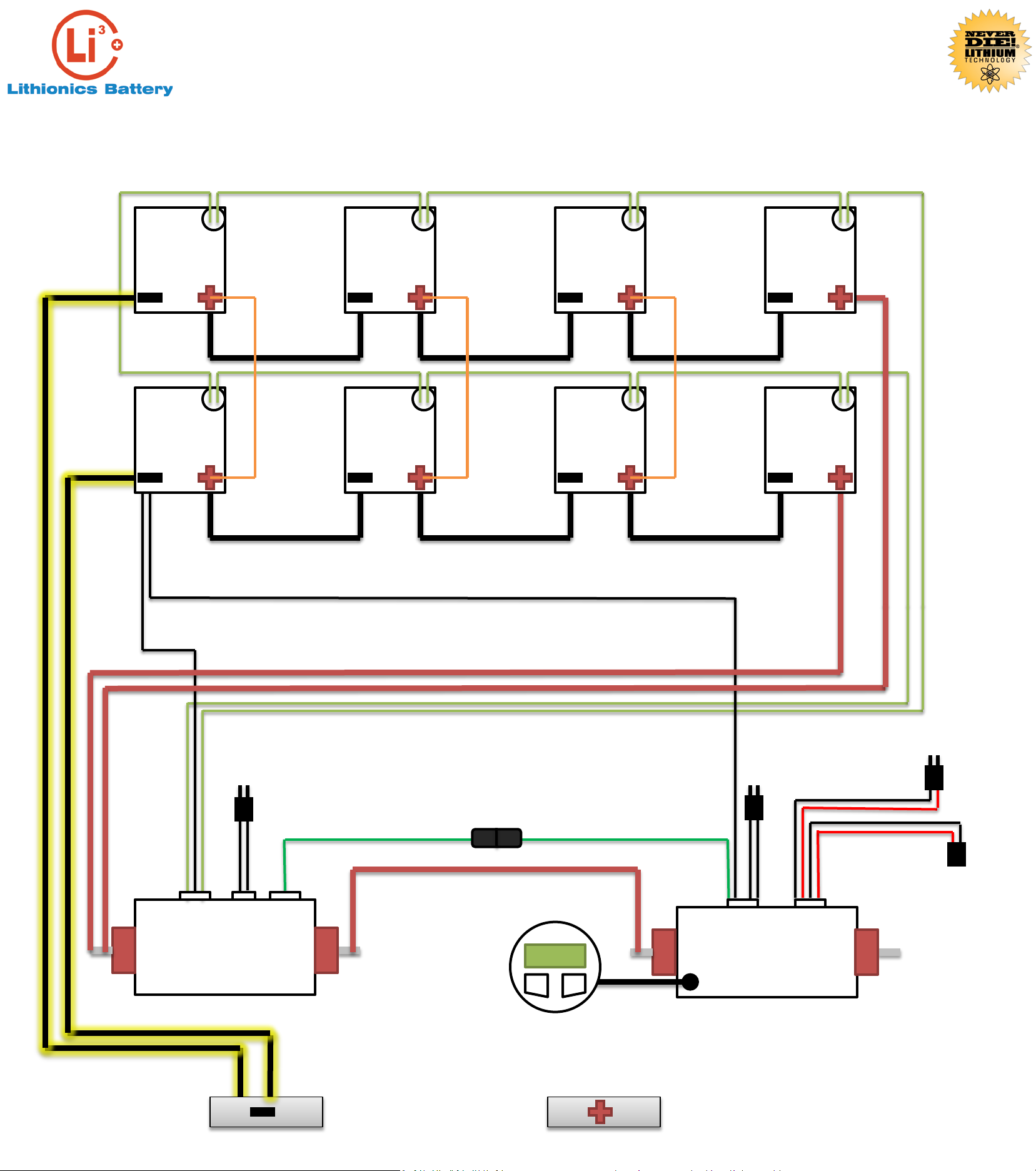
STEP 3: Connect the 12V Battery modules shown in parallel. This is to promote a better balanced system which
will increase the performance and life span of the battery system over time.
Cell loop Cell loopCell loop
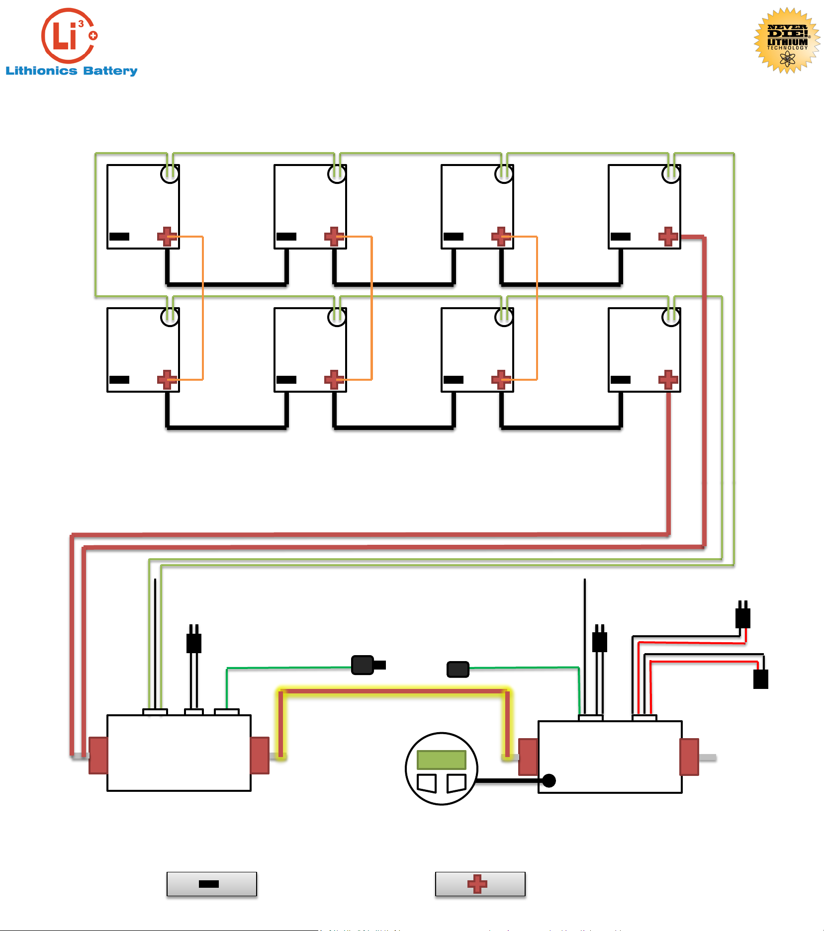
Series Connection
12V
Cell loop
12V
Cell loop
12V 12V
Series Connection
12V
Series Connection
12V
Series Connection
Series Connection Series Connection
Parallel Connection
Parallel Connection
Parallel Connection
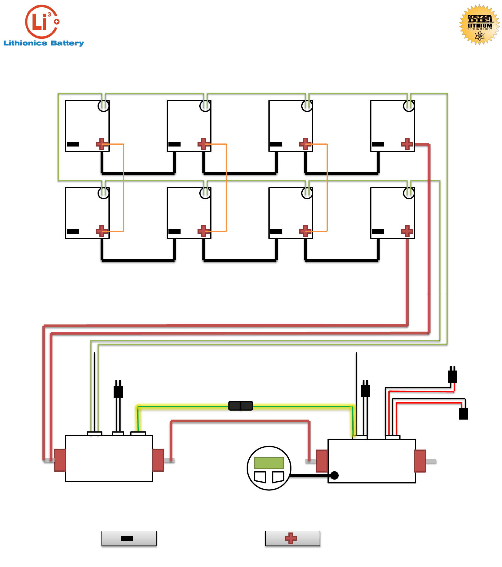
ALL POWER CABLES 2/0 AWG UNLESS
MARKED OTHERWISE
8AWG
8AWG
8AWG
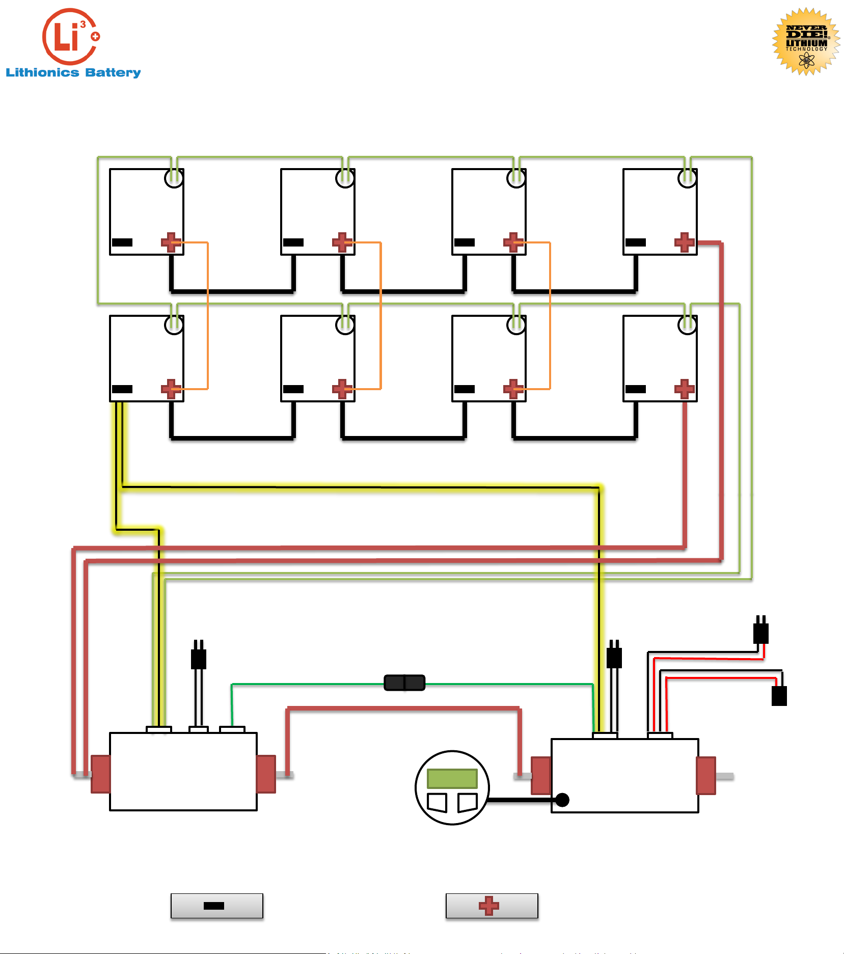
48V NeverDie Box
BATTERY
(+48V)
LOAD
(+48V)
48V
Discharge and Charge
Connection Point
5/2/14
DWG – NM
CKD – CH
48V SOC Sender Box
BATTERY
(+48V)
LOAD
(+48V)
SOC
AUX. RESET
SWITCH
HVC OUT HVC IN
GENERATOR
START/STOP
SWITCH
GEN. START SIGNAL
(20AWG)
GEN. RUN SIGNAL
(16AWG)
(INPUT 12-24V)