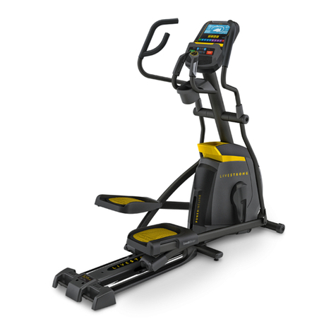
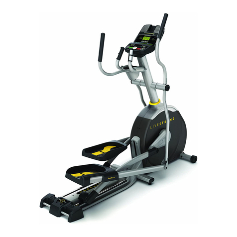
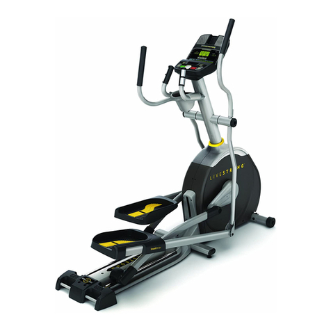
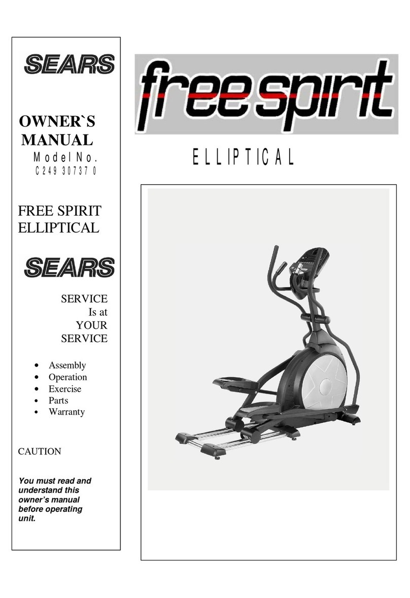
Livestrong LS7.9E User manual

Read the ELLIPTICAL GUIDE before using this OWNER’S MANUAL.
LS12.9ELS9.9ELS7.9E
ELLIPTICAL OWNER’S MANUAL

2
LIVESTRONG™ is a registered trademark of the Lance Armstrong Foundation.
The Lance Armstrong Foundation fights for the more than 25 million people around the world living with cancer today. There can be – and should be – life after cancer for more people. They
kick in at the moment of diagnosis, giving people the resources and support they need to fight cancer head-on. They find innovative ways to raise awareness, fund research and end the stigma
about cancer that many survivors face. They connect people and communities to drive social change, and call for state, national and world leaders to help fight this disease. Anyone, anywhere
can join the fight against cancer. Join them at LIVESTRONG.org.
INTRODUCTION
Congratulations and thank you for your purchase of this LIVESTRONG™ elliptical!
Purchases of this product ensure that a minimum of $4M will go to the Lance Armstrong Foundation and the fight against cancer.
Whether your goal is to win races or simply enjoy a fuller, healthier lifestyle, a LIVESTRONG™ elliptical can help you
attain it – adding club-quality performance to your at-home workouts, with the ergonomics and innovative features you
need to get stronger and healthier, faster. Because we’re committed to designing fitness equipment from the inside
out, we use only the highest quality components. It’s a commitment we back with one of the strongest frame-to-motor
warranty packages in the industry.
You want exercise equipment that offers the most comfort, the best reliability and the highest quality in its class.
LIVESTRONG™ ellipticals deliver.
3
ASSEMBLY
There are several areas during the assembly process that special attention must be paid. It is very important to follow the assembly
instructions correctly and to make sure all parts are firmly tightened. If the assembly instructions are not followed correctly, the
elliptical could have parts that are not tightened and will seem loose and may cause irritating noises. To prevent damage to the
elliptical, the assembly instructions must be reviewed and corrective actions should be taken.
Before proceeding, find your elliptical’s serial number located on the front stabilizer tube and enter it in the space provided
below. Also locate the model name which is next to the serial number.
ENTER YOUR SERIAL NUMBER AND MODEL NAME IN THE BOXES BELOW:
» Refer to the SERIAL NUMBER and MODEL NAME when calling for service.
» Be sure to enter both the SERIAL NUMBER and MODEL NAME on your warranty card.
WARNING
SERIAL NUMBER:
MODEL NAME: LIVESTRONG ELLIPTICAL

4
PIVOTING FOOT PADS
CRANK
TOP CAP
GUIDE RAIL SET
SPEAKERS
WATER BOTTLE HOLDER
UPPER HANDLEBAR
PULSE GRIPS
CONSOLE
REAR COVER
STABILIZER TUBE
POWER CORD SOCKET
MAIN FRAME
PEDAL ARM
IPOD/MP3 PLAYER POCKET
CONSOLE MAST
TOUCH PAD PANEL AND DISPLAY WINDOWS
LOWER HANDLEBAR
LOWER LINK ARM
LS7.9E

5
PIVOTING FOOT PADS
CRANK
INCLINE BRACKET
TOP CAP
GUIDE RAIL SET
SPEAKERS
WATER BOTTLE HOLDER
UPPER HANDLEBAR
PULSE GRIPS
REAR COVER
STABILIZER TUBE
POWER CORD SOCKET
MAIN FRAME
PEDAL ARM
IPOD/MP3 PLAYER POCKET
CONSOLE MAST
CONSOLE
BUTTONS AND DISPLAY WINDOWS
LOWER HANDLEBAR
LOWER LINK ARM
LS9.9E

6
PIVOTING FOOT PADS
CRANK
INCLINE BRACKET
TOP CAP
GUIDE RAIL SET
SPEAKERS
WATER BOTTLE HOLDER
UPPER HANDLEBAR
PULSE GRIPS
REAR COVER
STABILIZER TUBE
POWER CORD SOCKET
MAIN FRAME
PEDAL ARM
IPOD/MP3 PLAYER POCKET
INCLINE LEVEL TOGGLES
RESISTANCE LEVEL TOGGLES
CONSOLE MAST
CONSOLE
BUTTONS AND DISPLAY WINDOWS
LOWER HANDLEBAR
LOWER LINK ARM
LS12.9E

7
TOOLS INCLUDED:
FScrewdriver
F8 mm L-Wrench
F6 mm L-Wrench
F5 mm L-Wrench
F13/15 mm Flat Wrench
PARTS INCLUDED:
F1 Stabilizer Tube
F1 Guide Rail Set
F2 Pedal Arms
F2 Lower Handlebars
F2 Upper Handlebars
F2 Lower Link Arms With Footpads
F1 Top Cap (2 pieces)
F1 Console Mast
F1 Console Mast Boot
F1 Console
F2 Handlebar Caps
F1 Water Bottle Holder
F1 Rear Cover (LS9.9E, LS12.9E only)
F2 Sets Handlebar Covers (LS12.9E only)
F2 Aero Hand Grips (LS12.9E only)
F1 Audio Adapter Cable
F1 Power Cord
F9 Hardware Bags (LS12.9E) or...
F7 Hardware Bags (LS7.9E, LS9.9E)
UNPACKING
Unpack the product where you will be using it. Place the elliptical carton on a level
flat surface. It is recommended that you place a protective covering on your floor.
Never open box when it is on its side.
NOTE: During each assembly step, ensure that ALL nuts and bolts are in place
and partially threaded in before completely tightening any ONE bolt.
NOTE: A light application of grease may aid in the installation of hardware. Any
grease, such as lithium bike grease is recommended.
If you have questions or if
there are any missing parts,
contact Customer Tech
Support. Contact information
is located on the back panel
of this manual.
NEED HELP?
PRE ASSEMBLY
ALL
MODELS

8
ASSEMBLY STEP 1
A Open HARDWARE BAG 1.
B Attach the STABILIZER TUBE to the MAIN
FRAME using 4 BOLTS (A), 4 SPRING
WASHERS (B) and 4 ARC WASHERS (C).
BOLT (A)
30 mm
Qty: 4
SPRING WASHER (B)
15 mm
Qty: 4
ARC WASHER (C)
17 mm
Qty: 4
HARDWARE BAG 1 CONTENTS :
BOLTS (A)
SPRING WASHERS (B)
ARC WASHERS (C)
STABILIZER TUBE
MAIN FRAME
BOLTS (A)
SPRING WASHERS (B)
ARC WASHERS (C)
STABILIZER TUBE
MAIN FRAME
ALL
MODELS
LS7.9E SHOWN
LS9.9E, LS12.9E
SHOWN

9
LS7.9E ASSEMBLY STEP 2
* This step is for LS7.9E only.
A Open HARDWARE BAG 2.
B Align GUIDE RAIL SET with MAIN FRAME as
shown.
C Attach the GUIDE RAIL SET to the MAIN FRAME
using 4 BOLTS (D), 4 FLAT WASHERS (E) and 4
TOOTH WASHERS (G).
TOOTH WASHER (G)
15 mm
Qty: 4
FLAT WASHER (E)
17 mm
Qty: 4
BOLT (D)
55 mm
Qty: 4
HARDWARE BAG 2 CONTENTS :
TOOTH WASHERS (G)
FLAT WASHERS (E)
GUIDE RAIL SET
BOLTS (D)
MAIN FRAME
LS7.9E SHOWN
LS7.9E

10
LS9.9E, LS12.9E ASSEMBLY STEP 2
* This step is for LS9.9E, LS12.9E models only.
* LS7.9E models skip to STEP 3.
A Open HARDWARE BAG 2.
B Attach the GUIDE RAIL SET to the MAIN FRAME
using 4 BOLTS (D), 4 FLAT WASHERS (E) and 4
TOOTH WASHERS (G).
TOOTH WASHER (G)
15 mm
Qty: 4
FLAT WASHER (E)
17 mm
Qty: 4
BOLT (D)
55 mm
Qty: 4
HARDWARE BAG 2 CONTENTS (For Steps A–B):
TOOTH WASHERS (G)
FLAT WASHERS (E)
GUIDE RAIL SET
BOLTS (D)
MAIN FRAME
LS9.9E, LS12.9E ONLY
LS9.9E
LS12.9E

11
LS9.9E, LS12.9E ASSEMBLY STEP 2
C Attach the GUIDE RAILS to the MAIN FRAME
using 4 BOLTS (H), 4 FLAT WASHERS (I), 4
SPRING WASHERS (B) and 4 NUTS (J).
SPRING WASHER (B)
15 mm
Qty: 4
FLAT WASHER (I)
16 mm
Qty: 4
BOLT (H)
35 mm
Qty: 4
NUT (J)
Qty: 4
HARDWARE BAG 2 CONTENTS (For Step C) :
GUIDE RAILS
MAIN FRAME
BOLTS (H)
SPRING WASHERS (B)
FLAT WASHERS (I)
NUTS (J)
LS9.9E, LS12.9E ONLY
LS9.9E
LS12.9E

12
BOLT (M)
SPRING WASHER (B)
FLAT WASHER (K)
WAVY WASHER (L)
PEDAL ARM
CRANK
PEDAL ARM WHEEL
GUIDE RAIL
CONSOLE MAST
PRE-INSTALLED BOLTS
CONSOLE CABLE
MAIN FRAME
ASSEMBLY STEP 3
ALL
MODELS
A Open HARDWARE BAG 3.
B Carefully pull the CONSOLE CABLE through
the CONSOLE MAST using the twist tie located
inside the CONSOLE MAST.
C Gently slide the CONSOLE MAST onto the
MAIN FRAME and attach CONSOLE MAST to
MAIN FRAME using PRE-INSTALLED BOLTS.
D Slide WAVY WASHER (L) over CRANK
followed by PEDAL ARM as shown. Rest
PEDAL ARM WHEEL on GUIDE RAIL.
E Attach the PEDAL ARM to the CRANK using 1
FLAT WASHER (K), 1 SPRING WASHER (B)
and 1 BOLT (M).
F Repeat steps D–E on the opposite side of the
elliptical.
BOLT (M)
20 mm
Qty: 2
SPRING WASHER (B)
15 mm
Qty: 2
FLAT WASHER (K)
20 mm
Qty: 2
WAVY WASHER (L)
22.5 mm
Qty: 2
HARDWARE BAG 3 CONTENTS :LS9.9E, LS12.9E SHOWN
NOTE: Be
careful not
to pinch any
wires while
attaching the
console mast.

13
ASSEMBLY STEP 4
A Open HARDWARE BAG 4.
B Slide 1 FLAT WASHER (N), 1 WAVY WASHER
(L) and another FLAT WASHER (N) onto the
CONSOLE MAST.
C Slide LOWER HANDLEBAR onto CONSOLE
MAST and attach using 1 FLAT WASHER (N),
1 FLAT WASHER (K), 1 HANDLEBAR CAP, 1
FLAT WASHER (K) 1 SPRING WASHER (B)
and 1 BOLT (M).
D Repeat steps B–C on the opposite side of the
elliptical.
BOLT (M)
20 mm
Qty: 2
SPRING WASHER (B)
15 mm
Qty: 2
FLAT WASHER (K)
20 mm
Qty: 4
WAVY WASHER (L)
22.5 mm
Qty: 2
FLAT WASHER (N)
25 mm
Qty: 6
HARDWARE BAG 4 CONTENTS :LS12.9E SHOWN
BOLT (M)
SPRING
WASHER (B)
FLAT WASHERS (K)
FLAT WASHERS (N)
CONSOLE MAST
HANDLEBAR
CAP
LOWER HANDLEBAR
WAVY WASHER (L)
ALL
MODELS

14
BOLT (O)
SPRING WASHER (B)
FLAT WASHER (E)
FLAT WASHER (K)
BOLT (M)
NUT (J)
LOWER HANDLEBAR
SPRING WASHER (B)
TEFLON WASHERS (P)
LOWER LINK ARM
PEDAL ARM BRACKET
ASSEMBLY STEP 5
ALL
MODELS
A Open HARDWARE BAG 5.
B Slide LOWER LINK ARM onto PEDAL ARM
BRACKET.
C Attach LOWER LINK ARM to PEDAL ARM
using 1 FLAT WASHER (K), 1 SPRING
WASHER (B) and 1 BOLT (M).
D Align opposite end of LOWER LINK ARM with
bracket on bottom of LOWER HANDLEBAR.
NOTE: Be sure to remove the zip tie on the
LINK ARM.
E Place TEFLON WASHERS (P) on both sides of
the LOWER LINK ARM. While holding TEFLON
WASHERS (P) slide LOWER LINK ARM into
bottom end of LOWER HANDLEBAR.
F Secure the joint with 1 FLAT WASHER (E), 1
SPRING WASHER (B),1 BOLT (O) and secure
with 1 NUT (J).
G Repeat steps B–F on the opposite side of the
elliptical.
BOLT (M)
20 mm
Qty: 2
SPRING WASHER (B)
15 mm
Qty: 4
FLAT WASHER (K)
20 mm
Qty: 2 TEFLON
WASHER (P)
28.4 mm
Qty: 4
FLAT WASHER (E)
17 mm
Qty: 2
NUT (J)
Qty: 2
BOLT (O)
70 mm
Qty: 2
HARDWARE BAG 5 CONTENTS :
LS12.9E SHOWN

15
WATER
BOTTLE
HOLDER
CONSOLE MAST
SCREWS (Q)
SCREWS (Q)
REAR CAP
SCREWS (R)
REAR STABILIZER
CONSOLE
MAST
BOOT
TOP CAP
(LEFT & RIGHT)
LS9.9E
LS12.9E
LS9.9E, LS12.9E ASSEMBLY STEP 6
* This step is for LS9.9E, LS12.9E models only.
* LS7.9E skip to next page.
A Open HARDWARE BAG 6.
B Slide RIGHT AND LEFT TOP CAP over
CONSOLE MAST and attach using 3
SCREWS (Q).
C Slide CONSOLE MAST BOOT around
CONSOLE MAST and insert into TOP CAP.
D Slide WATER BOTTLE HOLDER over
CONSOLE MAST and attach using 2
SCREWS (R).
E Slide REAR CAP over REAR STABILIZER
and attach using 2 SCREWS (Q).
SCREW (Q)
15 mm
Qty: 5
SCREW (R)
15 mm
Qty: 2
HARDWARE BAG 6 CONTENTS :LS12.9E SHOWN
NOTE: Be careful not to pinch any
wires while tightening screws.

16
CONSOLE
MAST BOOT
TOP CAP
WATER
BOTTLE
HOLDER
CONSOLE MAST
SCREWS (S)
TOP CAP
REAR
COVER
LS7.9E
LS7.9E ASSEMBLY STEP 7
* This step is for LS7.9E only.
* LS9.9E, LS12.9E models skip to next page.
A Open HARDWARE BAG 7.
B Slide TOP CAP and TOP CAP REAR COVER
over CONSOLE MAST and snap into place.
C Insert CONSOLE MAST BOOT over TOP CAP
and snap into place.
D Slide WATER BOTTLE HOLDER over
CONSOLE MAST and attach using 2
SCREWS (S).
HARDWARE BAG 7 CONTENTS :
SCREW (S)
15 mm
Qty: 2
LS7.9E SHOWN
NOTE: Be careful not to pinch any
wires while tightening screws.

17
CONSOLE
BOLTS (T)
UPPER HANDLEBAR
(LS12.9E SHOWN)
CONSOLE CABLES
LOWER HANDLEBAR
HANDLEBAR WIRES
(LS12.9E ONLY)
PRE-INSTALLED
SET SCREWS
NOTCH
TAB
CONSOLE MAST
ALL
MODELS
A Open HARDWARE BAG 8.
B Attach the CONSOLE CABLES to the CONSOLE.
C Carefully tuck the CONSOLE CABLES into the
CONSOLE MAST before attaching the CONSOLE.
Attach CONSOLE to CONSOLE MAST using 4
BOLTS (T).
D Slide UPPER HANDLEBARS onto LOWER
HANDLEBARS and align NOTCH with TAB making
sure handlebars are joined together completely.
Secure UPPER HANDLEBARS to LOWER
HANDLEBARS using PRE-ATTACHED SET
SCREWS.
E LS12.9E ONLY: Connect the HANDLEBAR WIRES
from the UPPER HANDLEBAR to the wires from the
CONSOLE MAST.
F Repeat step D–E on other side.
ASSEMBLY STEP 8
BOLT (T)
12 mm
Qty: 4
HARDWARE BAG 8 CONTENTS :LS12.9E SHOWN
NOTE: Be careful not to pinch
any wires while attaching the
console or handlebars. LS7.9E, LS9.9E ASSEMBLY COMPLETE!

18
BOLTS (T)
UPPER HANDLEBAR
HANDLEBAR
WIRES
AERO HAND GRIPS
HANDLEBAR COVERS
SCREWS (Q)
* This step is for LS12.9E only.
A Open HARDWARE BAG 9.
B Connect the HANDLEBAR WIRES from the
right AERO HAND GRIP to the wires from the
UPPER HANDLEBAR. Attach AERO HAND
GRIP to the UPPER HANDLEBAR using 2
BOLTS (T).
NOTE: Be careful not to pinch any wires.
C Repeat on other side.
D Snap right HANDLEBAR COVERS over
handlebars and attach using 4 SCREWS (Q).
E Repeat on other side.
LS12.9E ASSEMBLY STEP 9
BOLT (T)
15 mm
Qty: 4
SCREW (Q)
15 mm
Qty: 8
HARDWARE BAG 9 CONTENTS :LS12.9E ONLY
NOTE: Be careful not
to pinch any wires while
attaching parts.
LS9.9E
LS12.9E
LS12.9E ASSEMBLY COMPLETE!

19
ELLIPTICAL OPERATION
This section explains how to use your elliptical’s console and programming.
The BASIC OPERATION section in the ELLIPTICAL GUIDE has instructions for the following:
• LOCATION OF THE ELLIPTICAL
• POWER/GROUNDING INSTRUCTIONS
• FOOT POSITIONING
• MOVING THE ELLIPTICAL
• LEVELING THE ELLIPTICAL
• POWER/MANUAL INCLINE OPERATION
• USING THE HEART RATE FUNCTION

20
DISTANCE
TIME
SPE E D
WATTS
CALORIES
HEART R ATE
MA NUAL RE V ER SE T RAI N
IN TE RVALS M OUNTAI N
WE IGH T LOSS C ONS TANT WAT TS
1
2
3
5
6
7
4
8
9
10
11
13
14
15
12
16
L S7.9E
CUS TOM
PRO GRAM
1
CUS TOM
PRO GRAM
2
SELECT
PRO GRAM ENTER
C H A N GE D IS PLAY
P R O G R A M M I N G C O N T R O L S
S T O P
HO LD TO R E SE T
S TA R T
QU ICK STAR T
L E V E L
LA
BB
G
H
F
E
C
J
I
F
M
D
N
O
K K
LS7.9E
Other manuals for LS7.9E
1
This manual suits for next models
2
Table of contents
Other Livestrong Elliptical Trainer manuals
Popular Elliptical Trainer manuals by other brands

Keys Fitness
Keys Fitness CardioMax 707 Elliptical CM707EL Specification sheet

Eco-De
Eco-De ECO-822 Instruction guide

cultsport
cultsport smartcross b1 user manual

Epic Fitness
Epic Fitness El 1710 Elliptical user manual

Image
Image 8.25 Elliptical user manual

Octane Fitness
Octane Fitness Q35 Operation manual