Nibe 057 315 User guide

Installer manual
Solar package
NIBE PV Solar cell package
IHB EN 2217-7
431707


41 Important information
4Safety information
4General
5Start-up protocol for solar panel system
72 Delivery, handling and maintenance
7Delivery
7Handling
7Maintenance
8Supplied components
93 Installation
9General
10Installation and positioning
11Functions
124 Mounting
12Installing solar panels in several groups
195 Electrical connection
19Outline diagram
226 Technical specifications
237 Accessories
23Solar package NIBE PV
24Item register
27Contact information
3Table of ContentsNIBE PV Solar cell package
Table of Contents

Safety information
This manual describes installation and service procedures
for implementation by specialists.
The manual must be left with the customer.
This appliance can be used by children
aged from 8 years and above and per-
sons with reduced physical, sensory or
mental capabilities or lack of experience
and knowledge if they have been given
supervision or instruction concerning use
of the appliance in a safe way and under-
stand the hazards involved. Children shall
not play with the appliance. Cleaning and
user maintenance shall not be made by
children without supervision.
This is an original manual. It may not be
translated without the approval of NIBE.
Rights to make any design or technical
modifications are reserved.
©NIBE 2022.
SYMBOLS
NOTE
This symbol indicates danger to person or machine.
Caution
This symbol indicates important information about
what you should consider when installing or servi-
cing the installation.
TIP
This symbol indicates tips on how to facilitate us-
ing the product.
MARKING
Explanation of symbols that may be present on the product’s
label(s).
General
RECOVERY
Leave the disposal of the packaging to the installer
who installed the product or to special waste sta-
tions.
Do not dispose of used products with normal
household waste. It must be disposed of at a special waste
station or dealer who provides this type of service.
Improper disposal of the product by the user results in ad-
ministrative penalties in accordance with current legislation.
COPYRIGHT
The manufacturer retains the copyright for this manual.
These instructions may only be distributed, translated or
copied with the written permission of the manufacturer. We
reserve the right to make changes to the specifications or
illustrations in this manual without prior notification.
NIBE PV Solar cell packageChapter 1 | Important information4
Important information

Start-up protocol for solar panel system
Start-up protocol, which is filled in by the installer.
Installer
Company:
Installer:
Telephone:
E-mail
Product
GoodweMake:
Model:
Inverter’s serial number:
Start-up date:
Connected to compatible NIBE product:
Inverter’s position:
Measurement values
The inverter is powered by the solar panels and will, for this reason, not start under all
conditions. Measuring the values below ensures that the installation has been performed
correctly.
☐ Inverter test-run/started
☐ Checked polarity from the solar panels
Current conditions (time, weather)
Voltage AC:
Voltage DC - String 1:
Voltage DC - String 2:
Voltage DC - String 3:
Voltage DC - String 4:
Notes / Other
Signature
Place and date:
Signature:
Clarification
5Chapter 1 | Important informationNIBE PV Solar cell package

Installation inspection, solar panels
Current regulations require the installation to undergo an installation inspection before it is commissioned. The inspection
must
be carried out by a suitably qualified person.
DateSignatureNotesDescription√
Mounting
All work is carried out in accordance with the installation instructions, regulations
and procedures regarding health, safety and the environment.
In the event of any deviations from the specifications, changes must be performed
in dialogue with, and according to the guidance of, the supplier.
Roof surface checked and measured prior to start of installation.
Roof structure and condition of mounting points checked.
Projecting rails cut outside of outer clamps.
All roof brackets have been installed in accordance with the instructions and
measures have been implemented to prevent damage caused by water, moisture
or other environmental factors.
No holes have been made unnecessarily in the roof, and penetrations that have
been created unintentionally or by mistake have been sealed.
Any damage to the product(s) has been reported to the supplier and rectified in
the agreed manner.
Electrical installation
Notification submitted to the power supplier, inverter data enclosed.
The property’s main fuse checked against power from solar panels.
Cables are installed in accordance with applicable rules and regulations.
All MC4 connectors/connections have been double-checked to ensure they are
correctly connected.
All cables are correctly routed and executed with suitable pipes, ducts or protection
indoors and outdoors.
All roof and wall lead-throughs are protected against water, moisture and other
environmental factors, and are executed in accordance with applicable rules and
regulations.
DC cables are clearly marked.
All voltages on the DC side have been measured and noted in the start-up protocol.
The PV system is connected to the AC network and the installation has been
functionally tested in accordance with the start-up protocol.
Make sure that the connections are tamper-proof, if the inverter is located where
it can be accessed by unauthorised parties.
Warning signs installed.
Notification of completion submitted to the power supplier.
Handover to the property owner completed.
Heat pump, where applicable
EME 20 is installed between inverter and heat pump.
EME 20 activated and communication checked in heat pump.
NIBE PV Solar cell packageChapter 1 | Important information6

Delivery
Together with the driver, check the delivery immediately for
the following:
•Visible damage (compressed packaging etc.)
•That the correct number of packages have been delivered
•That the solar panels in particular are undamaged.
Handling
Caution
Avoid knocks and mechanical damage to the solar
panel. Do not lift the solar panels by the connec-
tions. Do not place the solar panels on objects that
can damage them, nor pull or drag them over
anything that can damage them.
Maintenance
SERVICE
The solar panels must be regularly inspected.
Check that the glass in the panels and the aluminium frames
are not damaged.
Check that electrical wiring and connections are intact and
undamaged.
Mechanical cleaning is not usually required and is not recom-
mended.
7Chapter 2 | Delivery, handling and maintenanceNIBE PV Solar cell package
Delivery, handling and maintenance

Supplied components
PVK BASIC KIT
PVK 40-10
Monocrystalline silicon cell panels 10 pcs
Alu. rails, 10 pcs.
Alu. rail connectors 10 pcs.
Mountings for solar panels (assembly clamps) 24 pcs
Connectors for electrical connection between the panels
and the inverter, male and female, (electrical cable not in-
cluded) 4 + 4 pcs
PV cable with pre-installed connectors 7 metres 2 pcs
PVK 40-20
Monocrystalline silicon cell panels 20 pcs
Alu. rails 20 pcs.
Alu. rail connectors 20 pcs.
Mountings for solar panels (assembly clamps) 48 pcs
Connectors for electrical connection between the panels
and the inverter, male and female, (electrical cable not in-
cluded) 8 + 8 pcs
PV cable with pre-installed connectors 7 metres 4 pcs
INVERTER
UN
Inverters 1 pcs
Rating plates for electrical installation 4 pcs
EME 20 1 pcs
ROOF BRACKET PRM XX-20, 20 PCS
(AVAILABLE FOR VARIOUS ROOF TYPES)
PRM 11-20 Tiled roof
PRM 61-20 Retrofit kit, horizontal installation for tiled roof
PRM 21-20 Sheet metal roof
PRM 41-20 Felt roof1
PRM 31-20 Seamed sheet metal roof
PRM 51-20 Universal for aluminium rails
Lower section for the roof bracket is not supplied by NIBE
Additional fastening for the relevant roof type is required
1See section Mounting brackets for solar panels on felt roof on page 16 for further information.
NIBE PV Solar cell packageChapter 2 | Delivery, handling and maintenance8

General
The installation must only be carried out by competent
personnel.
The enclosed materials are those required for the installa-
tions described (see page 12),. In special cases, these may
need to be supplemented. If in doubt, contact your supplier.
Information on the applicable standards and regulations
must be obtained prior to installation and commissioning.
The electrical installation, as well as the notification to the
network operator, must be carried out by a qualified electri-
cian. Please note that commissioning the installation before
the network operator has given its approval is not permitted.
NOTE
Installation of a solar panel is an extensive inter-
vention on an existing roof. The roof covering,
particularly on converted and inhabited loft spaces
or where the roof's minimum angle is undersized
(relative to the covering), may require further
measures against moisture because of wind pres-
sure and drifting snow, this must be evaluated by
the installer on a case to case basis. The roof
design must be able to handle the wind and snow
loading that can occur in the region.
STATIC LOAD
The installation is only permitted to be performed on roof
surfaces or support structures with sufficient carrying ca-
pacity and strength. If necessary, the static load capacity
of the roof and roof structure must be investigated before
the solar panels are installed. Great importance should be
placed on the condition of wooden roof structures and the
possibilities for screwing the mounting devices for the solar
panels to the structure. The roof structure must be rein-
forced if necessary. Inspection of the whole solar panel in-
stallation in accordance with DIN 1055 part 4 and 5, or in
accordance with country-specific regulations, is required,
in particular in areas that experience snowfall and strong
winds. The characteristics of the installation’s location
(prevailing wind direction, whirlwinds, etc.) must also be in-
cluded in the calculation/estimate if these could involve in-
creased loads. The solar panels must be installed so that
snowdrifts resulting from snow guards or due to special
conditions in the installation location cannot occur in the
vicinity of the solar panels.
The distance from the outer edges of the roof must be at
least 0.35 m at the sides of roofs and 0.2 m at ridges and
eaves, in order to reduce the risk of the wind ripping the
solar panels off.
The installation system according to DIN 1055 part 5 for
snow zone II is intended for use up to 400 m above sea level.
If the installation is made on a tiled roof, it is recommended
that the snow is cleared if it reaches a depth of more than
30 cm on the solar panels (NOTE! If the snow has melted,
been packed down and then more snow has fallen and so
the density has increased, the snow may need to be cleared
- even though it is not 30 cm deep.)
If there is a risk that the snow will slide down onto the panels
and in particular behind the rear of raised panels, snow
guards must be installed to prevent this.
Also ensure that the material under roofs with roof tiles is
sufficiently stable to support the roof mounting points.
Otherwise the roof must be reinforced. The installer must
evaluate this and make a decision. If in doubt, a structural
engineer needs to be consulted. We also recommend that
the roof tiles should be ground down so there are no point
loads between the roof and the roof brackets. The minimum
distance between roof tiles at overlap points and the under-
side of the brackets is 3 mm, in order to allow for any
movements in the mounting system due to the loads that
can arise.
SAFETY INSTRUCTIONS
•Safety regulations for working on roofs and similar struc-
tures must be followed.
•Protection against falling parts must be installed. This is
particularly important in locations where people pass be-
low the roof/building.
•Personal safety equipment and/or scaffolding must be
used when working on roofs, according to applicable reg-
ulations.
•Suitable measures must be taken during installation to
ensure that the solar panel does not come loose and fall.
•Observe the safety distance to live conductors.
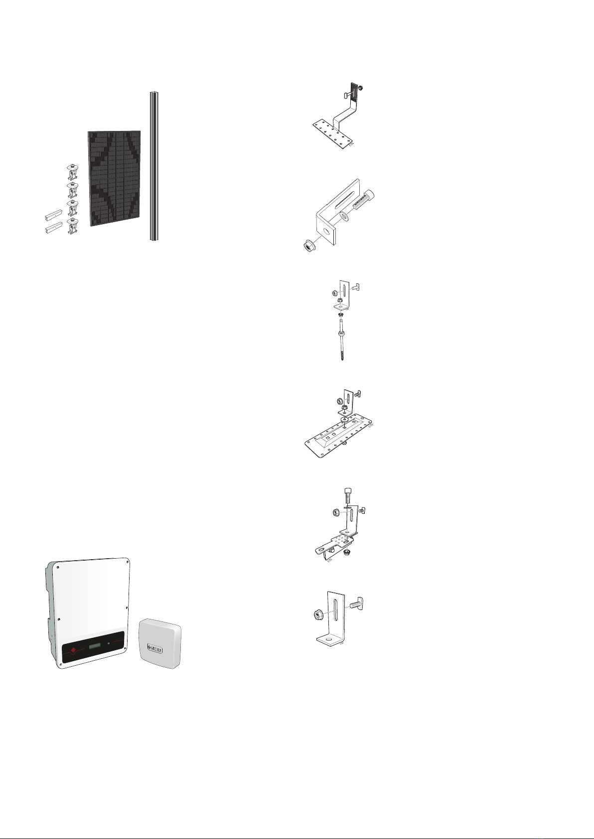
9Chapter 3 | InstallationNIBE PV Solar cell package
Installation

Installation and positioning
Using the map and the diagram, it is possible to estimate
the annual value of the insolation on the surface where the
solar panels are placed.
100% is the insolation at a horizontal surface. The angle of
inclined surfaces is 45°.
The diagram shows insolation as a percentage of global ra-
diation in relation to surfaces at various orientations and
angles.
The map shows lines with the same global radiant flux, i.e.
the insolation measured at horizontal surfaces.
700
700
700
800
800
800
900
900
900
1000
1000
1000
1000
1000
1100
1100
1100
1100
1100
1200
1200
1200
1100
1400
1400
1400
1400
1400
1600
1500
1700
1600
1600
1600
1600
1800
1800 1800
1700
1. Calculate the annual solar radiation using the map. The
specific solar radiation for the installation is obtained
as a percentage, based on the location of the solar
panel according to the diagram.
2. Multiply the results by the installation’s peak output
(e.g. 4 / 8 / 12 / 16 / 20 kW).
3. Multiply the result 2 by a constant 0.9 to calculate the
energy production in kWh/year (with a reservation for
shade, dirt and snow coverage).
Example: Prague, 8 kW, 45°, installation south (112 %).
1120 x (112/100) x 8 x 0.9 = 9032 kWh/year
NIBE PV Solar cell packageChapter 3 | Installation10

Functions
MYUPLINK / NIBE UPLINK
With myUplink and the Internet, you can obtain a quick
overview and the current status of the solar panel system
on your property. You receive easy-to-grasp and good
supporting data, where you can see the current power and
the history. In the event of any malfunction, you also receive
an alarm directly in the app, which allows you to take prompt
countermeasures. myUplink requires the accessory EME 20,
which is enclosed with the inverter.
WIFI COMMUNICATION MODULE
CMO 11 / CMO 22
With this accessory, you can connect the inverter to its portal
without myUplink.
CMO 11/22 communicates with your home network via wifi.
See separate manual for more information and installation.
CMO 11 is used for inverter PVI 10 and CMO 22 is used for
PVI 20.
11Chapter 3 | InstallationNIBE PV Solar cell package

Installing solar panels in several
groups
Examples of possible combinations per ten panels:
To reduce the risk of damage to the electric cables between
the groups of solar panels, these can be run underneath the
roof tiles or ceiling. To prevent moisture penetrating under
the roof tiles or through the damp barrier at the holes for
the electrical cables, diffusion sealed lead-ins must be fitted.
Horizontal installation
The rails are installed vertically in the case of horizontal
mounting. Remember that extra roof brackets and clamps
are required.
Horizontal installation on a tiled roof also requires a retrofit
kit PRM 61-20.
Specially adapted roof brackets for tiled roofs, sheet metal
roofs, felt roofs or seamed sheet metal roofs. The type of
roof bracket to be used must be specified when ordering. If
the panels are installed in a different formation, additional
mounting materials may be required.
Caution
Additional connectors and mounting materials may
be required to install solar panels in different
groupings.
ADDITIONAL PANELS
Each package can be expanded with additional panels (PVK
40-1).
This means that you have extremely good flexibility, allowing
attractive roof installation.
Caution
Check that the inverter can cope with the total
power with additional panels.
Example
8 kW package installed on roof that is expanded by e.g. four
solar panels (9.6 kW)
8 kW package installed on roof where it was decided not to
install e.g. two panels (7.2 kW).
NIBE PV Solar cell packageChapter 4 | Mounting12
Mounting

Number of solar panels per string and per package
The table shows how many panels you can have per string, as well as how many panels are standard and how many the
inverter can cope with. The inverter has dual trackers, allowing the installation of different numbers of panels per string.
If the number of panels is not sufficient to achieve the minimum number for two strings, you have to install all the panels
in one string.
String = a number of panels connected in series.
Rec. max.
total
Min.
total
Std./
no.
Max./
string
Min./
string
Inverter
rec. max. DC:
PVI
94-943.9 kW10-31
136101365.2 kW20-4
206202068 kW20-6
3263020613 kW20-10
406402x20 2
616 kW20-12
506502x202
620 kW20-15
11x230 V.
2Tracker one can manage one string or two equally long strings.
OVERVIEW, ASSEMBLY PARTS
NOTE
Ensure that the strength and load-bearing capa-
city of the roof structure are sufficient.
NOTE
If there is not a sufficiently stable substructure
such as tongued and grooved boards or roof
trusses to allow a durable installation the roof must
be reinforced.
Roof bracket Mounting rail, horizontal
Joint with rivet
Assembly clamps
BEFORE INSTALLING SOLAR PANELS
63
5
5
4
1
2
24 mm
Roof bracket location
1. Number of rows of installed solar panels x height of
solar panels (plus distance between the solar panels
where relevant).
2. Number of solar panels installed horizontally x (solar
panel's width + 24 mm) + 31 mm.
3. The horizontal distance between the mounting points
for the roof brackets must not exceed c-c 1200 mm.
4. Solar panel height
5. Vertical location of the mounting points = panel height
x 0.25.
6. Max distance between the last roof bracket and the end
of the mounting rail = 200 mm
13Chapter 4 | MountingNIBE PV Solar cell package

CABLE ROUTING
Cable with pre-installed connectors (PVK 40-10: 2x7 m, PVK
30-20: 4x7 m) is supplied and can be used as a return cable
for roof installation. For more information, see chapter
"Electrical connection" on page 19.
REMOVE THE ROOF TILES
Mark out the positions for the roof brackets using chalk.
Remove or slide up the marked roof tiles.
Caution
The image is only an example. For dimensions
between roof brackets, see the section "Before
installing solar panels" above.
ROOF BRACKETS IN TRUSS OR IN TONGUE AND
GROOVE
xx
Roof bracket
Tongue and
groove/Truss
Secure each roof bracket in the trusses with 3 x wood
screws. 2 x screws are located in the lower groove and 1 x
screws are located in the upper groove (screws not sup-
plied).
Caution
The distance to the edge (X) must be the same on
both sides.
Installing the roof brackets in tongued and
grooved boards
Secure each roof bracket with 6 x stainless steel construc-
tion screws, divided between the two grooves (screws not
supplied).
NIBE PV Solar cell packageChapter 4 | Mounting14

SPACER PLATES
Spacer plate Wood screw
Roof bracket
Battens
Tongued
and
grooved
board
Roof tile
Truss
Counter-
battens
The roof bracket must not be pressed directly against the
roof tile. Use a spacer plate if necessary?
The spacer plate must be made of a water and weather-
resistant material (not supplied).
ADAPTING ROOF TILES
Use an angle grinder to make a cut-out in the part of the
roof tile that covers the roof bracket, so the roof tile can lie
against the substrate.
It may also be necessary to do this in the roof tile under-
neath.
HANGER BOLT FOR SHEET METAL ROOF
UN
Roof profile
Battens
Counter-
battens
Tongued and
grooved
board
Truss
4
1. Drill holes in the roof tile or use existing holes
2. Install the screw pin in the truss sufficiently deeply, (all
the threaded section must be screwed in), to install a
seal against the roof sheet. A bitumen based roof and
building sealant can be used - required for textured
(sanded) surfaces
3. Install the L profile, adjust the height to the other screw
pins
4. Ensure that the screw pin’s entire thread is screwed into
the roof truss.
15Chapter 4 | MountingNIBE PV Solar cell package

MOUNTINGBRACKETSFORSOLARPANELSON
SEAMED SHEET METAL ROOF
LEK
Bolt M10
Washer
Mounting
L profile
Nut M10
1. Install the mounting on the roof according to the usual
rules and practice
2. Install the L profile with M10 bolt, washer and nut.
MOUNTINGBRACKETSFORSOLARPANELSON
FELT ROOF
This applies for the installation of felt on a wooden roof,
such as a garage roof. Depending on the roof structure,
other felt/membrane variants may require different brackets.
In such cases, consult a certified roofer.
In such cases, the PRM 51 universal mount may be required.
x 10
LEK
LEK
Screw
Coach bolt M10
1. Install the plate on the roof according to the usual rules
and practice.
x 10
LEK
LEK
Coach bolt M10
Flashing tape
Rubber washer
L profile
Nut M10
2. Install the L profile on the protruding coach bolt with M10
nuts.
Caution
The coach bolt should be installed from under-
neath before the plate is mounted on the roof.
Caution
Never use the installed roof brackets as a ladder.
MOUNTING RAILS
Standing panels
Mounting rails are secured in the roof brackets with T bolts
and locking nuts (8 mm).
NIBE PV Solar cell packageChapter 4 | Mounting16

Landscape panels
The PRM 61 retrofit kit is required for landscape panels.
Caution
Check that the head of the T-bolt is vertical in the
mounting rail after tightening.
The rectangular hole in the roof bracket permits optimal
height adjustment of the mounting rail.
Adjustment of the mounting rail height
Adjust the first mounting rails installed in relation to each
other and the roof cladding. Then fix the mounting rail to
the roof bracket by tightening the nut. Tightening torque
12-15 Nm.
JOIN THE MOUNTING RAILS
2mm
Slide the joint section with rivets into the mounting rail until
it catches firmly on the raised part. Slide on the next
mounting rail until it also catches on the raised part. Leave
a space of 2 mm to compensate for thermal expansion.
A wider expansion joint is required after 21 panels, the joint
must measure at least 100 mm.
INSTALLING SOLAR PANELS IN THE FIRST
(BOTTOM) ROW
90°
Caution
The assembly clamps can be twisted and are adap-
ted for use both at the outer edges and between
the solar panels.
1. Position the first solar panel on the mounting rail.
2. Click the assembly clamp into the first (bottom) row 5
mm from the end of the mounting rail.
17Chapter 4 | MountingNIBE PV Solar cell package

3. Secure the solar panel with the assembly clamp screw,
tighten to 8 Nm.
4. Click the assembly clamp into the installation rail on the
right-hand side of the solar panel. Slide the assembly
clamp towards the solar panel and connect.
5. Position the second solar panel on the mounting rail and
move the solar panel towards the assembly clamp.
Connect the cable to the previous solar panel. Secure
the wiring between the solar panels.
6. Tighten the assembly clamp, tighten to 12-15 Nm.
7. Install further solar panels according to point 4 to 6.
8. After the last solar panel in the row 1 has been posi-
tioned on the mounting rail and connected, the assembly
clamp is clicked into the mounting rail from the right.
Minimum distance between the assembly clamp and
the end of the mounting rail is 5 mm.
9. Secure the solar panel with the assembly clamp screw,
tighten to 8 Nm.
Caution
Secure the wiring between the solar panels.
Caution
Take the return cable when installing the
panels. See section Electrical connec-
tion/Cable routing
Caution
Measure the voltage at the connected panels
on the roof before removing any scaffolding.
Install the following rows in the same way.
NIBE PV Solar cell packageChapter 4 | Mounting18

Outline diagram
LEK
LEK
45
3
2
HBIJF JF HB 2 11 H1IB 5L
1678910 11 2TR HK
AIA 566
LEK
Solar panels
Heat pump /
indoor module or
control module
EME 20
Inverter
myUplink*
Internet
Own use
domestic
electricity
Electricity meter
own use (optional)
Electrical
distribution unit
Electricity meter
network owner
* myUplink for the S-series and NIBE Uplink for the F-series.
NOTE
Electrical installation and service must be carried
out under the supervision of a qualified electrician,
and in accordance with applicable electrical safety
regulations.
Factory-fitted junction boxes prepared with cables for pos-
itive and negative connections can be found on the reverse
of the solar panels. The cables are fitted with quick-release
connectors.
The electrical cables between the panels and the inverter
must be double insulated and UV/weather-resistant
photovoltaic cables, 4 mm² up to 100 m length (not supplied).
The inverter is connected and fused to the fuse panel as if
it was a load with the same output. The inverter includes a
factory-fitted 300 mA residual current device. If the inverter
is to be connected to an external residual current device,
this must be 300 mA or larger and of type A.
NOTE
The inverter is powered by the voltage from the
solar panels. At night and in poor light, the inverter
may therefore be switched off.
LIGHTNING PROTECTION
There are occasions when lightning protection can affect
how the installation is installed. See the applicable laws and
regulations.
NOTE
In order to minimise the risk of induced voltages
in the event of lightning, the return cable must be
laid together with connection cables for the panels
connected in series.
19Chapter 5 | Electrical connectionNIBE PV Solar cell package
Electrical connection

INSTALLING
CONNECTORS ON DC
WIRING
DC connectors of the MC-4 type
are supplied with all packages.
1. The connector’s sleeve must
not be disconnected until the
cable has been inserted into the
connector.
1
15 - 16,5 mm
2. Strip the cable 15-16.5 mm
2
3. Twin the cable’s strands.
4
CLICK
4. Insert the cable into the con-
nector until a “click” is heard.
5
Test
5. Check that the cable is se-
curely in place by carefully
pulling it.
6
3 - 4 Nm
6. Fasten the connector’s sleeve
so that the cable is secure and
so that the sleeve is at the bot-
tom (3-4 Nm)
Caution
Check that the polarity is correct when connecting
to the inverter.
CONNECTING INVERTERS
For assembly and installation, consult the quick guide. For
more information about the inverter, consult the enclosed
manual.
QUICK GUIDE
Installation area
≥ 300mm
≥300mm
≥ 800mm
≥ 200mm ≥ 200mm
Hole pattern for the bracket
a
b
c
d
f
e
PVI 20-XXPVI 10-3
200 mm250 mma
100 mm125 mmb
45 mm120 mmc
-240 mmd
--e
-265 mmf
Fitting the wall bracket
NIBE PV Solar cell packageChapter 5 | Electrical connection20
This manual suits for next models
7
Table of contents
Other Nibe Inverter manuals