llaza MOONBOX 400 User manual

1
Fecha / Date: 10 Julio 2018 / 10th July 2018
REF. 45098068001
REV. 1.1
MOONBOX-400
Manual de Fabricación
Assembly manual

2
0.1–Descripción del producto / Product description
0.2–Leyenda / Icon legend
Usar con sol
Use with sun
No usar con nieve
Don’t use with snow
No usar con lluvia
Don’t use with rain
No usar con granizo
Don’t use with hail
Uso con sol y lluvia
Use with sun and rain
Clasicación por ciclos /
Class by N. of cicles
Manivela
Crank
Motorizado
Motorized
¡Atención! tensión brazos
Danger! Strong arm tension
ART-250
Splendor 300
ART-350
Splendor 400
Onyx
WIN
ART-500
Barra de carga EVO
EVO front prole
B. carga Univers
Univers front prole
28 Km/h
38 Km/h
Información
Informaon
Fabricado en Europa
Made in Europe
Marcado CE
CE standards
Inox
Línea
Width
Salida
Projecon
2 años de garana
2 years of warranty
3 años de garana
3 years of warranty
Eco-friendly
MOONBOX 400
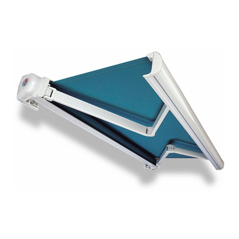
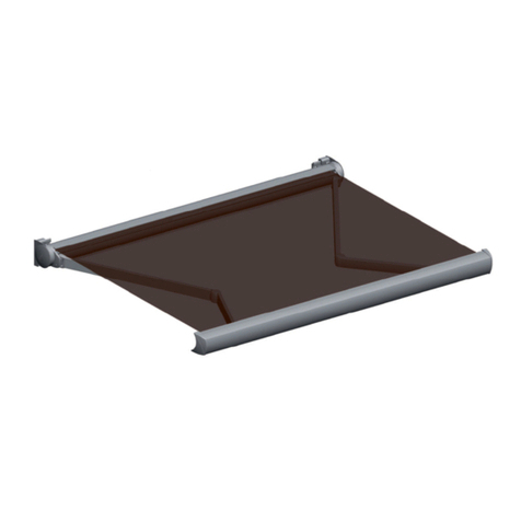
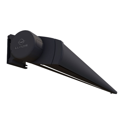
El diseño del toldo Cofre Moonbox 400 está inspirado en las formas oblicuas de las órbitas planetarias.
La regulación del ángulo de inclinación es por sistema de cremallera, pudiendo realizarse con el toldo cerrado.
Permite dimensiones de 6,00m. de línea sin soportes intermedios y 4 metros de proyección.
Posibilidad de incorporar perl suplemento tejadillo para quedar pegado a la pared.
Embellecedores y tapas laterales totalmente de aluminio para una mayor resistencia y posibilidades estécas.
The design of the Moonbox 400 cassee awning is inspired by oblique shapes of planetary orbits.
The adjustment of the inclinaon angle can be modied through its rack system even the cassee is closed.
This model allows a width of 6.00 m. with no need of intermediate supports and 4.00 m. projecon.
Addional complementary top prole to completely cover the gap between the cassee prole and the back wall.
All side caps are made in lacquered aluminium for a higher resistance and state-of-the-art design.

3
1.1.–Línea/ Width
1.2.–Salida/ Projection
1.3..–Secciones acotadas / Section dimensions
MOONBOX 400
L
S
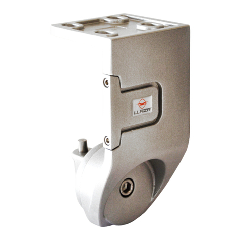
Placa de sustentación Frontal/Techo
Fixing plate: Wall/Ceiling

4
2.1.- Despiece del producto / Product parts
2.2.–Nomenclatura / Nomenclature
ESTE CONJUNTO TAMBIÉN SE PUEDE CONFIGURAR CON BRAZOS ONYX
THIS MODEL CAN ALSO BE ASSEMBLED WITH ONYX ARMS
MOONBOX 400

5
3.1.–Compatibilidades / Compatibilities
Brazos / Arms B.carga / Front prole
4.1.–Tablas de corte de perfiles y tejido / Allowances for profiles and fabric
MotorMáquina Interior / Interior Gearbox
Perl Cofre Tejadillo/ Cassete-top prole L-129L-129
Perl Cofre/ Cassete prole L-129L-181
Perl Protector Lona/ Fabric protector prole L-129L-131
Perl Frontal de carga/ Front prole L-129L-129
T/Enrolle Ø70 - Ø80 /Rolling tube Ø70 - Ø80 L-173L-187
Lona / Fabric L-183L-197
Perl Suplemento Tejadillo / Supplement top prole L-67L-67
Salida / Projecon (m) Línea mínima / Minimum width (m)
1,50 1,86
1,75 2,14
2,00 2,39
2,25 2,64
2,50 2,89
2,75 3,14
3,00 3,39
3,25 3,64
3,50 3,89
3,75 4,14
4,00 4,39
Línea mínima / Minimum width (m)
Descuentos Confección / Allowances
MOONBOX 400

6
7.1 –Información de maniobras y clase / Information about cycles and class
Los brazos llevan una banda protectora de colores para su idencación:
VERDE: Visto desde fuera, lado derecho
ROJA: Visto desde fuera, lado izquierdo
NUNCA EXTRAER LAS BANDAS DE SEGURIDAD PARA LA TENSIÓN HASTA HABER SUJETADO EL BRAZO AL PERFIL DE CARGA.
NEVER EXTRACT THE SAFETY TENSION BANDS UNTIL THE ARM HAS BEEN FIXED TO THE FRONT PROFILE.
6.1 –Clasificación según norma Europea / Classification according to European standards : EN 13.561:2015
Salida brazo / Arm projecon (m) Línea / Width Clase / Class
4,00 6,00 C.1
The arms have a protecve band for correct idencaon:
GREEN: Right hand side viewed from outside
RED: Le hand side viewed from outside
5.1- Tablas de selección motor / Motor selection charts
MOONBOX 400
Tubo de enrolle de Ø70 / Ø 70mm rolling tube
Brazos / Arms
2
Linea / Width (m)
2,00 2,50 3,00 3,50 4,00 4,50 5,00 5,50 6,00 6,50 7,00
Salida
Projec-
on (m)
1,50 30 30 30 30 30 30 30 30 30 30 30
2,00 30 30 30 30 30 30 30 30 30 30
2,50 30 30 35 35 35 35 35 35 35 35
3,00 35 35 35 35 40 40 40 40 40 40
3,50 40 40 40 40 40 40 40 50 50 50
4,00 40 40 40 50 50 50 50 50 50 50
Tubo de enrolle de Ø80 / Ø 80mm rolling tube
Brazos / Arms
2
Linea / Width (m)
2,00 2,50 3,00 3,50 4,00 4,50 5,00 5,50 6,00 6,50 7,00
Salida
Projec-
on (m)
1,50 30 30 30 30 30 30 30 30 30 30 30
2,00 30 30 35 35 35 35 35 35 35 35
2,50 35 35 35 40 40 40 40 40 40 40
3,00 40 40 40 40 50 50 50 50 50 50
3,50 50 50 50 50 50 50 50 50 50 50
4,00 50 50 50 50 50 50 50 50 50 50
7
8.1.–Instrucciones de fabricación / Assembly instructions
8.2.–Instrucciones de fabricación / Assembly instructions
8.3.–Instrucciones de fabricación / Assembly instructions
MOONBOX 400
Componentes del kit de tapas y soportes /
Caps and brackets set
Fijación soporte para motor / Bracket Fixaon for motor operaon
IMPORTANTE / IMPORTANT
Observar la posición nal del protector lona /
Observe the nal posion for the fabric protector prole
Introducir el perl protector lona en el perl cofre /
Insert the fabric protector prole in the cassee prole
Pegar las ras de espuma, a 25 cm a cada lado del centro
del cofre / Ax the foam strips at 25 cm from each side
of the awning center.

8
8.4.–Instrucciones de fabricación / Assembly instructions
8.5.–Instrucciones de fabricación / Assembly instructions
8.6.–Instrucciones de fabricación / Assembly instructions
MOONBOX 400
Antes de añadir el perl tejadillo, jar soporte brazo lado accionamiento al perl cofre/ Fix the arm support to the cassee
prole before adding the top prole.
¡ATENCIÓN! TORNILLO MÁS CORTO PARA FIJACIÓN
MÁQUINA
ATTENTION! IN CASE OF MANUAL OPERATION, USE
HERE THE SHORT SCREW TO FIX THE GEARBOX
A
A
A/B
Tornillo A: Ø 4,2 x 45
Tornillo B: Ø 4,2 x 25 (lado máquina)
Sujetar el cabezal del motor mediante el clip de jación / Fasten
the motor head with the xing clip
Accionamiento motor / Motor operaon
Colocar el rodamiento en su alojamiento y jar el perl cofre
al soporte brazo / Place the bearing in its housing and x the
cassee prole to the arm support.
Fijación soporte lado punta /
End side support xaon
En caso de accionamiento máquina, consultar las instrucciones al nal de manual (9.1) / In case of manual opera-
on, please check the instrucons at the end of this manual (9.1)

9
8.7.–Instrucciones de fabricación / Assembly instructions
8.9.–Instrucciones de fabricación / Assembly instructions
Colocar goma selladora en el
perl tejadillo / Place the rub-
ber sealant prole in the slot of
the top prole
MOONBOX 400
IMPORTANTE / IMPORTANT
Colocar dos tuercas M6 en el soporte lateral para después montar las chapas laterales. Es aconsejable sujetarlas con los tor-
nillos / Place two M6 nuts in the side bracket and x them with the screws. They will be used laer to x the side cups.
¡ATENCIÓN! / ATTENTION!
Para cofre a techo, hay que tener en cuenta la posición de
las tuercas / In case of ceiling mounng, pay aenon to the
nuts posion.
Ensamblar el perl tejadillo en el perl cofre y jarlo al
soporte brazo / Mount the top prole to the cassee pro-
le and x it to the arm support
Posición correcta de los soportes después de montar el sistema de
regulación / Support correct posion aer the adjustment system
has been mounted
Montar cremallera en el tornillo de regulación / Thread seng in the adjustment screw
Roscar la cremallera hasta el nal para regulación frontal / Thread the zipper to the end for frontal adjustment
Frontal
Dejar 1cm sin roscar para regulación a techo / Leave 1 cm without thread for ceiling adjustment
Techo / Ceiling
8.8.–Instrucciones de fabricación / Assembly instructions

10
8.10.–Instrucciones de fabricación / Assembly instructions
MOONBOX 400
Extraer el espárrago de sujeción para poder montar el brazo /
Remove the subjecon stud bolt before mounng the arm
Mediante el giro de la llave allen se consigue el nivel ópmo de alineación del brazo /
By turning the allen wrench the opmum level of alignment is achieved
IMPORTANTE / IMPORTANT
Observar la posición nal del terminal una vez insertado /
Observe nal posion of the front rail connector once it has been mounted
Los terminales llevan una marca de idencación: derecha con la letra “R” e izquierda con la letra “L” / The
front rail connectors come with an idencaon mark: “R” for right hand side and “L” for le hand side
(looking at the awning from outside)
8.11.–Instrucciones de fabricación / Assembly instructions
Una vez regulado el brazo, apretar el espárrago / Once the level of the arm is in the
desired posion, then fasten the threaded stud

11
8.12.–Instrucciones de fabricación / Assembly instructions
8.13.–Instrucciones de fabricación / Assembly instructions
MOONBOX 400
Si en el perl de carga se quiere instalar bambalina/faldón,
primero se tendrá que quitar la pestaña del perl (el perl no
tendrá la posibilidad de llevar luces led) / I
In case of installing balance in the front prole, the alumini-
um tap from the slot has to be removed. Aer doing so, it will
not be possible to install led lighng in the same slot any-
more.
Introducir la vaina del tejido en el perl de carga./
Insert the fabric in the front prole.
Introducir ahora los terminales por los laterales del perl de
carga / Insert the front rail connectors in its right posion in
the corresponding slot of the front prole.
8.14.–Instrucciones de fabricación / Assembly instructions
200mm
Distancia de posicionamiento de los terminales
desde el extremo del corte del perl de carga al
extremo del terminal / Posioning distance for
the front rail connectors measured from the
end of the front prole to the outer end of the
front rail connector.
Después montar el taco de nylon y su tornillo en la raunura de la lona /
Then introduce the set of screw+plug in the fabric hem to x the fabric in
its slot.

12
8.15.–Instrucciones de fabricación / Assembly instructions
8.16.–Instrucciones de fabricación / Assembly instructions
MOONBOX 400
Montar la chapa al perl de carga con los tornillos rosca
chapa / Mount the plate to the front prole with the cor-
responding screws
Colocar en la tapa los panes de deslizamiento / Place the
sliders in the cap
Patin horquilla / Fork slider
Patin Codo / Elbow slider
Posicionamiento del pan horquilla y del pan codo en el perl de carga del cofre Moonbox 400 /
Posion of the fork slider and the elbow slider inside the front prole from the Moonbox 400
Montar y jar la tapa en el perl frontal con el tornillo
de M6 / Fix the cap in the front prole using the M6
screw
8.17.–Instrucciones de fabricación / Assembly instructions
Posicionamiento de los topes redondos de silicona en el perl cofre /
Posion of the round silicone stops on the cassee prole.

13
8.18.–Instrucciones de fabricación / Assembly instructions
MOONBOX 400
8.19.–Instrucciones de fabricación / Assembly instructions
Montar chapa lateral / Mounng the side
plate
Montaje suplemento tejadillo:
1) Insertar las gomas
2) Montar el soporte jación con los tornillos 4,2 x 45.
3) Montar la chapa lateral con los tornillos 4,2 x 13
4) Incorporar al conjunto cofre y jarlo con los
tornillos M6
A
A
B
B
Tornillo/Screw A: Ø 4,2 x 45
Tornillo/Screw B: Ø 4,2 x 13
Fijación de salida del cable motor / Fixing
the output of the motor cable
Montar en la tapa cofre la chapa con los mecanis-
mos de plásco y el tornillo de M6 / Mount the
plate in the cassee side cover using the plasc
elements and the M6 screw
8.20.–Instrucciones de fabricación / Assembly instructions
1)
Mounng the top cover prole:
1) Introduce the sealant proles
2) Fix the cover support with the 4,2 x 45 screws (A)
3) Fix the cover side plate with the 4,2 x 13 screws (B)
4) Mount the top cover on the cassee using the M6 screws
2)
3)
4)

14
8.21.–Instrucciones de fabricación / Assembly instructions
MOONBOX 400
Finalmente ulizaremos el tornillo de nylon para sujetar la tapa cofre con el soporte brazo / Fix the cassee side cover by
means of the nylon screw
8.22.–Instrucciones de fabricación / Assembly instructions
La ranura inferior del perl frontal se complementa con un perl difusor / The lower slot in the front prole is
equipped with a diuser prole
El perl difusor cubre la ranura y actúa como embellece-
dor aunque no se instale la ra de led para iluminación /
The diuser prole can be placed as a concealment ele-
ment even if there is no led strip inserted in the slot
La ra de led se ja en la ranura a través de su capa autoadhesiva / The led strip can be axed in the slot through its
self-adhesive layer
8.23.–Instrucciones de fabricación / Assembly instructions

15
MOONBOX 400
8.24.- Instrucciones de instalación —Installation instructions
Ejemplos de instalación de ras led control vía radio / Wiring examples for led strips controlled by hand transmier
8.25.–Instrucciones de fabricación / Assembly instructions
Ejemplos de instalación de ras led control vía radio en brazos Onyx Lux / Wiring example for led strips installed with ONYX-
LUX arms

16
MOONBOX 400
9.1.–Anexo instalación con máquina elevadora / Instructions for gearbox operation
Kit accionamiento máquina Ref. 20074052_ _ _ / Gearbox operaon kit Art. N. 20074052_ _ _
9.2.–Anexo instalación con máquina elevadora / Assembling for gearbox operation
Unir la extensión al perl cofre para habilitar el accionamiento máquina / Aach the extension kit to cassee box
prole in order to enable the gearbox operaon
A
A
A
A
A
B
Tornillo/Screw A: Ø 4,2 x 16
Tornillo/Screw B: Ø 4,2 x 13
Tornillo corto /
Short screw
RL

17
9.3.–Anexo instalación con máquina elevadora / Assembling for gearbox operation
MOONBOX 400
Ensamblaje de ambos tramos del perl / Assembly of both
prole secons
Apriete de tornillos y tuercas de ambos lados de las chapas /
Fasten screws and nuts from both sides of the plates.
9.4.–Instrucciones de fabricación / Assembly instructions
IMPORTANTE / IMPORTANT
Observar la posición nal del protector lona /
Observe the nal posion for the fabric protector prole
Introducir el perl protector lona en el perl cofre /
Insert the fabric protector prole in the cassee prole
Pegar las ras de espuma, a 25 cm a cada lado del centro
del cofre / Ax the foam strips at 25 cm from each side
of the awning center.
Antes de añadir el perl tejadillo, jar el soporte brazo al perl cofre/ Fix the arm support to the cassee prole before ad-
ding the top prole.
¡ATENCIÓN! TORNILLO MÁS CORTO PARA FIJACIÓN
MÁQUINA
ATTENTION! IN CASE OF MANUAL OPERATION, USE
HERE THE SHORT SCREW TO FIX THE GEARBOX
A
A
A/B
Tornillo/Screw A: Ø 4,2 x 45
Tornillo/Screw B: Ø 4,2 x 25 (lado máquina)
9.5.–Instrucciones de fabricación / Assembly instructions

18
MOONBOX 400
9.6.–Instrucciones de fabricación / Assembly instructions
Fijar el kit máquina / Fix the gearbox kit
9.7.–Instrucciones de fabricación / Assembly instructions
Fijación tapa máquina / Fixing the gearbox cap
¡ATENCIÓN! LA TAPA GUADA MANO: R-Derecha L-Izquierda
ATTENTION! OBSERVE THE SIDE OF EACH CAP: R-Right L-Le hand side
9.8.–Instrucciones de fabricación / Assembly instructions
Incorporar del tubo de enrolle con el tejido en el agujero de
la máquina/ Mount the Rolling tube with the fabric in the
gearbox square opening
Connuar el resto del montaje como indicado en la versión motor a parr del monta-
je de la parte punta/ Follow up with the assembly from the end support xaon

19
MOONBOX 400

20
LLAZA WORLD, S.A.
Tramuntana, 1. Pol.Ind. Roques Roges
43460 ALCOVER
Tel. +34 977 990 600 / Fax +34 977 990 610
e-mail: [email protected] / e[email protected]
Other llaza Accessories manuals

llaza
llaza STORBOX 300 User manual

llaza
llaza SPLENBOX 300 User manual

llaza
llaza SPLENBOX 400 User manual

llaza
llaza STORBOX 250 User manual

llaza
llaza STORBOX 300 User manual

llaza
llaza COMPLET-PRO 350 User manual

llaza
llaza SPLENBOX 400 User manual

llaza
llaza SPLENBOX 300 User manual

llaza
llaza MONOBOX-400 User manual
Popular Accessories manuals by other brands

netvox
netvox ZB11A1 user manual

STIEBEL ELTRON
STIEBEL ELTRON SRC C analog Operation and installation

Dutch Thermal Engineering
Dutch Thermal Engineering CoolMaster K2 Series operating manual

Steren
Steren smart home SHOME-100 instruction manual

Girard Systems
Girard Systems G-Link G-2000 Owners Operation, Adjustment, Repair & Installation Manual

Chamberlain
Chamberlain 915GA install guide